5 GHz Up-Converter Mixer with Cross-Coupled Oscillator#
Warning
This documentation is currently a work in progress.
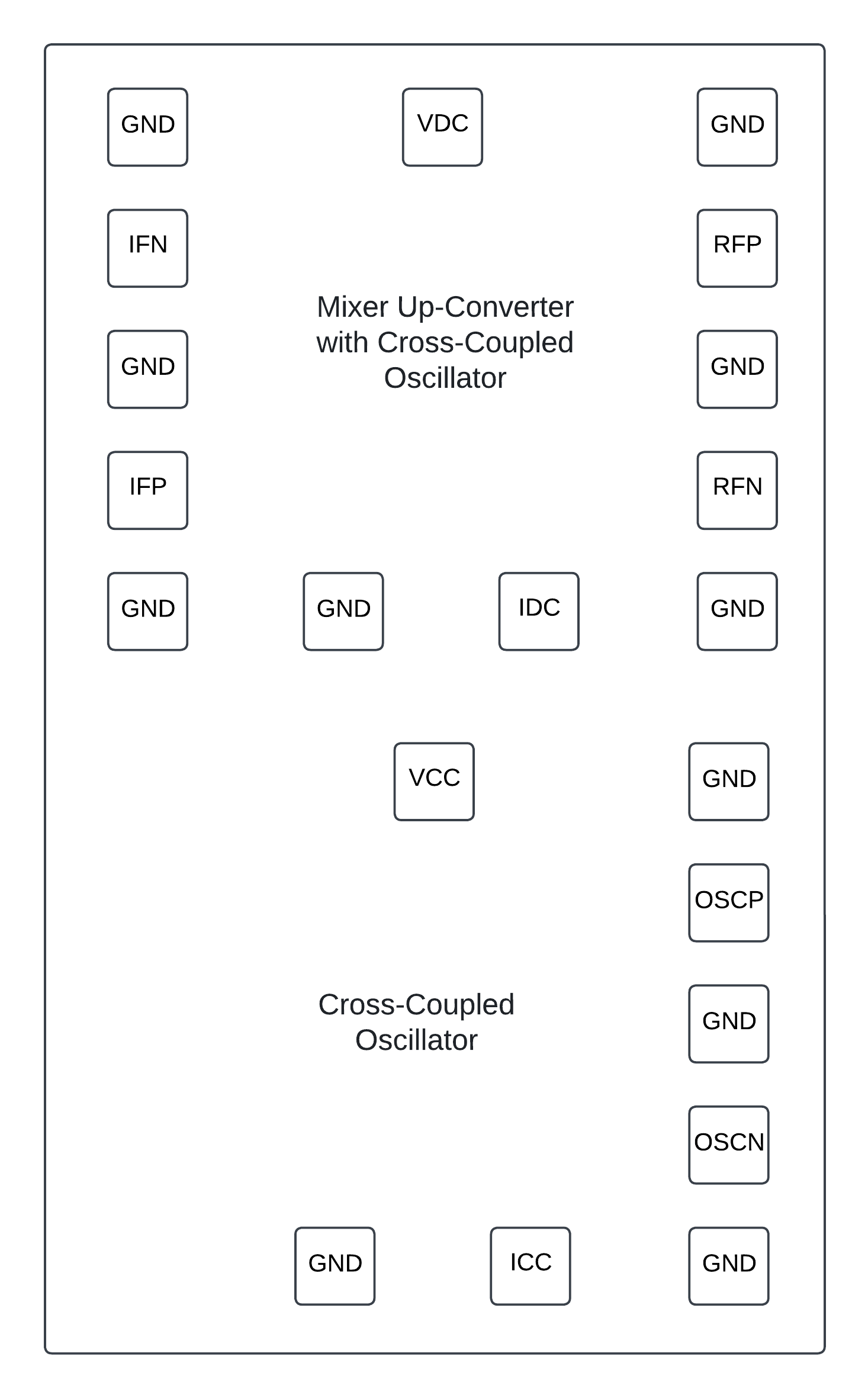
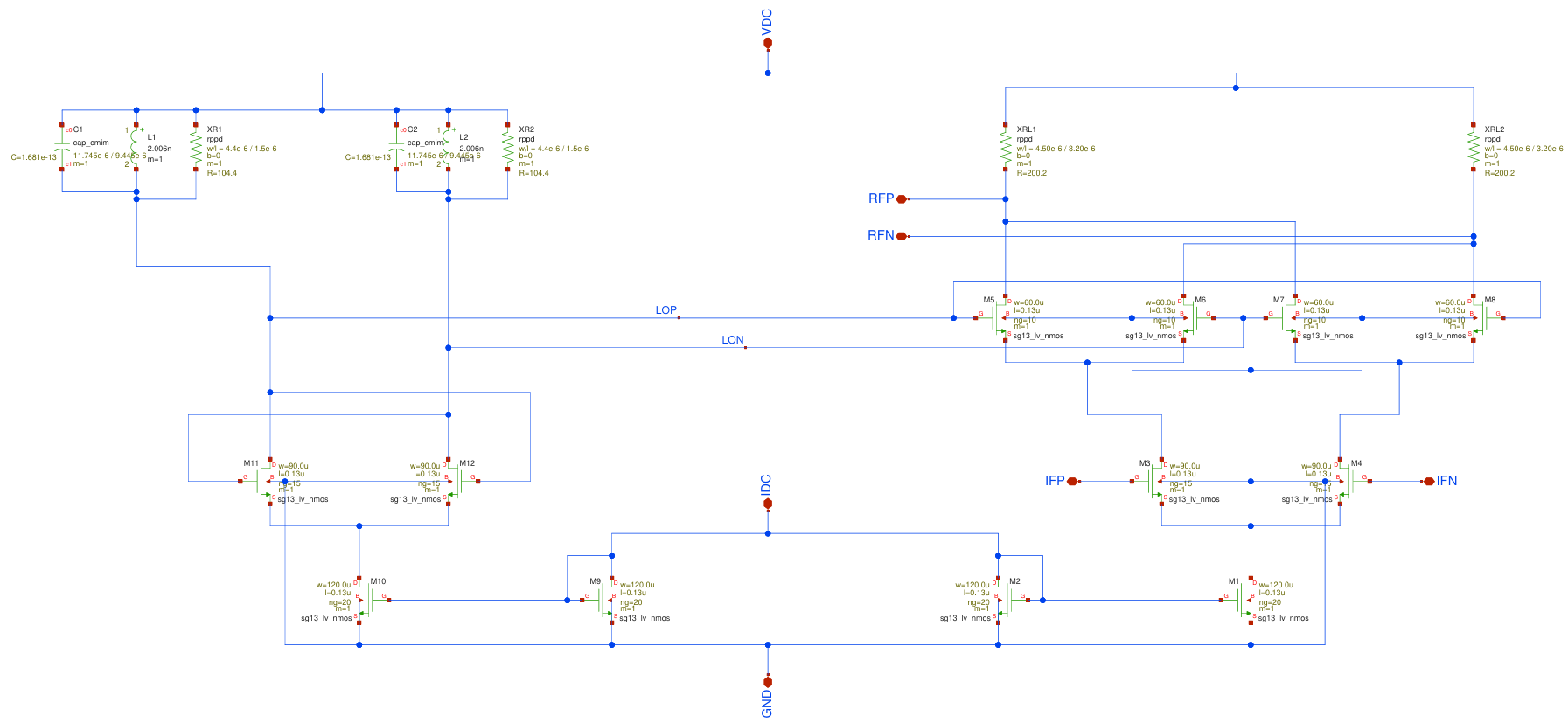
Mixer Up-Converter with Cross-Coupled Oscillator:
IFP and IFN: Differential input pair
RFP and RFN: Differential output pair
VDC: Power supply terminal
IDC: Bias current terminal
GND: Ground terminal
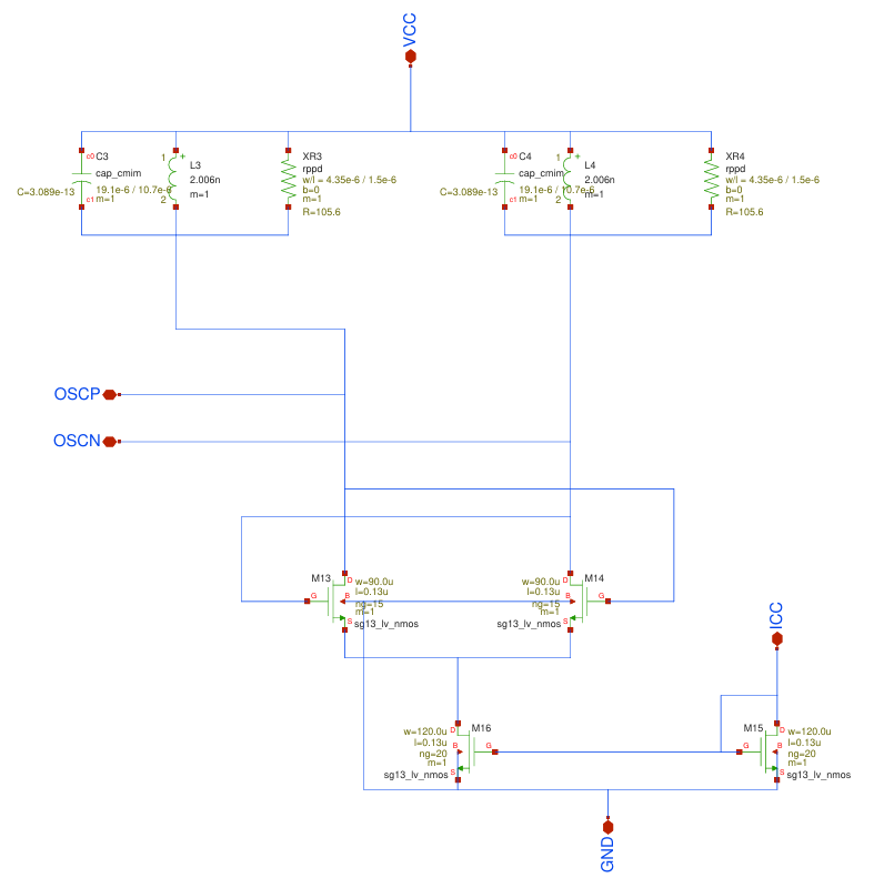
Cross-Coupled Oscillator:
OSCP and OSCN: Differential output pair
VCC: Power supply terminal
ICC: Bias current terminal
GND: Ground terminal
Understanding the operation of electronic circuits applied in low-temperature environments is crucial for the implementation of systems aimed at quantum computing. This is because, in cryogenic environments, material properties and device behavior can differ significantly from those observed at conventional temperatures.
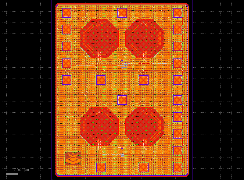
To characterize circuits at both conventional and cryogenic temperatures, a chip was developed to test the behavior of the designs proposed below.
Mixer Up-Converter with Cross-Coupled Oscillator
Cross-Coupled Oscillator
Chip Pinout#