One-Port vs Two-Port Inductor Resonance
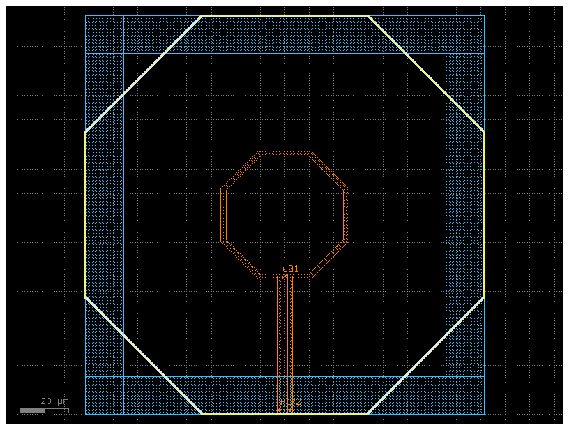
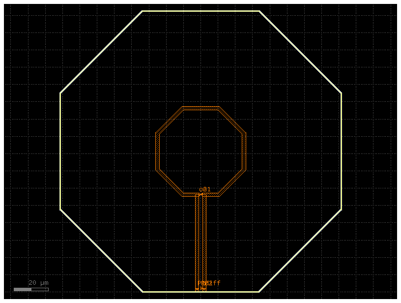
This experiment addresses issue #257 by comparing two ways to excite the same single-turn inductor:
- Two-port: two 50 Ω
interlayerports from the TopMetal2 terminals to a Metal1 guard ring. - One-port: one 50 Ω
gapport directly between the two floating TopMetal2 terminals, with no guard ring.
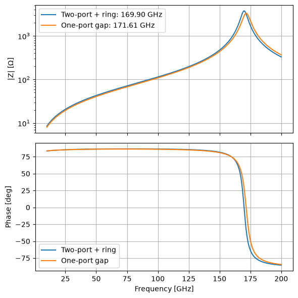
Both sweeps use 501 points from 10 to 200 GHz. Because the physical reference conductor changes, this comparison measures the combined effect of port definition and guard-ring loading, not port count alone.
from pathlib import Path

import gdsfactory as gf
import matplotlib.pyplot as plt
import numpy as np
from ihp import PDK

from gsim.palace import DrivenSim

PDK.activate()

PORT_IMPEDANCE_OHM = 50.0
FREQUENCY_MIN_HZ = 10e9
FREQUENCY_MAX_HZ = 200e9
NUM_FREQUENCY_POINTS = 501
TRACE_WIDTH_UM = 2.0
TRACE_SPACE_UM = 2.1
DIAMETER_UM = 50.0
Build the two geometries
The winding dimensions are identical. Only the port/reference structure differs.
def build_inductor() -> gf.Component:
    return gf.components.inductor(
        width=TRACE_WIDTH_UM,
        space=TRACE_SPACE_UM,
        diameter=DIAMETER_UM,
        turns=1,
        layer_metal="TopMetal2drawing",
        layer_inductor="INDdrawing",
        layer_metal_pin="TopMetal2drawing",
        layers_no_fill=("NoMetFillerdrawing",),
    ).copy()


def add_guard_ring(component: gf.Component, width: float = 15.0) -> None:
    bbox = component.bbox()
    outer_left, outer_bottom = bbox.left, bbox.bottom
    outer_right, outer_top = bbox.right, bbox.top
    inner_left, inner_bottom = outer_left + width, outer_bottom + width
    inner_right, inner_top = outer_right - width, outer_top - width
    overlap = 0.5

    rectangles = (
        (
            (width + overlap, outer_top - outer_bottom),
            (
                outer_left + width / 2 + overlap / 2,
                (outer_top + outer_bottom) / 2,
            ),
        ),
        (
            (width + overlap, outer_top - outer_bottom),
            (
                outer_right - width / 2 - overlap / 2,
                (outer_top + outer_bottom) / 2,
            ),
        ),
        (
            (outer_right - outer_left, width + overlap),
            (
                (outer_right + outer_left) / 2,
                outer_top - width / 2 - overlap / 2,
            ),
        ),
        (
            (outer_right - outer_left, width + overlap),
            (
                (outer_right + outer_left) / 2,
                outer_bottom + width / 2 + overlap / 2,
            ),
        ),
    )
    for size, center in rectangles:
        ring_section = component.add_ref(
            gf.components.rectangle(size=size, layer="Metal1drawing", centered=True)
        )
        ring_section.move(center)

    if inner_left >= inner_right or inner_bottom >= inner_top:
        raise ValueError("Guard-ring width leaves no open center.")


def add_differential_gap_port(component: gf.Component) -> float:
    first_terminal = component.ports["P1"]
    second_terminal = component.ports["P2"]
    first_center = np.asarray(first_terminal.center, dtype=float)
    second_center = np.asarray(second_terminal.center, dtype=float)
    if not np.isclose(first_center[1], second_center[1]):
        raise ValueError("The gap port requires aligned terminals.")

    center_separation = abs(second_center[0] - first_center[0])
    terminal_gap = (
        center_separation
        - (float(first_terminal.width) + float(second_terminal.width)) / 2
    )
    if terminal_gap <= 0:
        raise ValueError("The inductor terminals do not have a positive gap.")

    component.add_port(
        name="Pdiff",
        center=tuple((first_center + second_center) / 2),
        width=float(terminal_gap),
        orientation=0,
        layer="TopMetal2drawing",
        port_type="electrical",
    )
    return float(terminal_gap)


two_port_component = build_inductor()
add_guard_ring(two_port_component)
one_port_component = build_inductor()
terminal_gap_um = add_differential_gap_port(one_port_component)
terminal_gap_um
2.1
two_port_display = two_port_component.copy()
two_port_display.draw_ports()
two_port_display.plot()

one_port_display = one_port_component.copy()
one_port_display.draw_ports()
one_port_display.plot()
Configure both 50 Ω simulations
def configure_common_simulation(
    simulation: DrivenSim, component: gf.Component, output_dir: Path
) -> None:
    simulation.set_output_dir(output_dir)
    simulation.set_geometry(component)
    simulation.set_stack(substrate_thickness=180.0, include_substrate=True)
    simulation.set_driven(
        fmin=FREQUENCY_MIN_HZ,
        fmax=FREQUENCY_MAX_HZ,
        num_points=NUM_FREQUENCY_POINTS,
    )
    simulation.set_airbox(margin_x=50, margin_y=50, z_above=50, z_below=5)


two_port_sim = DrivenSim()
configure_common_simulation(
    two_port_sim, two_port_component, Path("palace-sim-inductor-two-port")
)
for port_name in ("P1", "P2"):
    two_port_sim.add_port(
        port_name,
        from_layer="metal1",
        to_layer="topmetal2",
        impedance=PORT_IMPEDANCE_OHM,
        geometry="interlayer",
    )

one_port_sim = DrivenSim()
configure_common_simulation(
    one_port_sim, one_port_component, Path("palace-sim-inductor-one-port")
)
one_port_sim.add_port(
    "Pdiff",
    layer="topmetal2",
    impedance=PORT_IMPEDANCE_OHM,
    geometry="gap",
)

print("Two-port:", two_port_sim.validate_config())
print("One-port:", one_port_sim.validate_config())
Two-port: Validation: PASSED
One-port: Validation: PASSED
two_port_sim.mesh(preset="default", refined_mesh_size=1.5)
one_port_sim.mesh(preset="default", refined_mesh_size=1.5)
Small conductor feature detected (2.000 um) may be under-resolved by refined_mesh_size=1.500 um. The heuristic target is <= 1.000 um (2 cells/feature). Reduce refined_mesh_size; auto_size=True preserves an explicit size.


Small conductor feature detected (2.000 um) may be under-resolved by refined_mesh_size=1.500 um. The heuristic target is <= 1.000 um (2 cells/feature). Reduce refined_mesh_size; auto_size=True preserves an explicit size.


Mesh Summary
========================================
Dimensions: 152.1 x 207.3 x 250.9 µm
Nodes:      10,668
Elements:   78,569
Tetrahedra: 59,569
Edge length: 0.57 - 70.15 µm
Quality:    0.622 (min: 0.179)
SICN:       0.678 (all valid)
Worst element distortion, κ: 12.6603 (tet centers; 1 is ideal)
Estimated Field DOFs: 379,848 (order 2; before Palace preprocessing)
Mesh hash:  sha256:5b9ea5912593474c  (gmsh 4.15.2, gsim 0.8.0)
Mesher:     2D algorithm 5, 3D algorithm 1, threads 1 (1D/2D/3D limits 1/1/1)
----------------------------------------
Volumes (4):
  - silicon [1]
  - sio2 [2]
  - sin [3]
  - air [4]
Surfaces (9):
  - topmetal2_xy [5]
  - topmetal2_z [6]
  - P1 [7]
  - air__silicon [8]
  - silicon__sio2 [9]
  - air__sio2 [10]
  - sin__sio2 [11]
  - air__sin [12]
  - air__None [13]
----------------------------------------
Mesh:   palace-sim-inductor-one-port/palace.msh
Run and save the S-parameters
check_cache=True reuses matching cloud results when available.
two_port_results = two_port_sim.run(check_cache=True)
one_port_results = one_port_sim.run(check_cache=True)

two_port_sparams_path = two_port_results.save_npz(
    Path("palace-sim-inductor-two-port") / "sparams"
)
one_port_sparams_path = one_port_results.save_npz(
    Path("palace-sim-inductor-one-port") / "sparams"
)
two_port_sparams_path, one_port_sparams_path
  palace-d5eeea9c  [####################] 100%  complete  elapsed 0m 00s


Extracting results.tar.gz...
Downloaded 12 files to sim-data-palace-d5eeea9c


(PosixPath('palace-sim-inductor-two-port/sparams.npz'),
 PosixPath('palace-sim-inductor-one-port/sparams.npz'))
Convert both results to terminal-to-terminal impedance
For the two-port result, \(Z_\mathrm{diff}=Z_{11}-Z_{12}-Z_{21}+Z_{22}\). The one-port gap result is already differential, so its impedance is \(Z_{11}\).
from gsim.palace import differential_impedance, s_to_z


def s_parameter_matrix(results) -> np.ndarray:
    port_names = results.port_names
    matrix = np.empty(
        (len(results.freq), len(port_names), len(port_names)), dtype=complex
    )
    for row, to_port in enumerate(port_names):
        for column, from_port in enumerate(port_names):
            matrix[:, row, column] = results[(to_port, from_port)].complex
    return matrix


two_port_frequency_ghz = np.asarray(two_port_results.freq)
one_port_frequency_ghz = np.asarray(one_port_results.freq)
if not np.allclose(two_port_frequency_ghz, one_port_frequency_ghz):
    raise RuntimeError("The simulations returned different frequency grids.")

two_port_z = s_to_z(s_parameter_matrix(two_port_results), z0=PORT_IMPEDANCE_OHM)
two_port_differential_z = differential_impedance(two_port_z)
one_port_z = differential_impedance(
    s_to_z(s_parameter_matrix(one_port_results), z0=PORT_IMPEDANCE_OHM)
)
def estimate_resonance_ghz(frequency_ghz: np.ndarray, impedance: np.ndarray) -> float:
    peak_index = int(np.argmax(np.abs(impedance)))
    if peak_index == 0 or peak_index == len(frequency_ghz) - 1:
        return float(frequency_ghz[peak_index])

    fit_indices = slice(peak_index - 1, peak_index + 2)
    coefficients = np.polyfit(
        frequency_ghz[fit_indices],
        np.log(np.abs(impedance[fit_indices])),
        deg=2,
    )
    return float(-coefficients[1] / (2 * coefficients[0]))


two_port_resonance_ghz = estimate_resonance_ghz(
    two_port_frequency_ghz, two_port_differential_z
)
one_port_resonance_ghz = estimate_resonance_ghz(one_port_frequency_ghz, one_port_z)
resonance_shift_ghz = one_port_resonance_ghz - two_port_resonance_ghz

{
    "two_port_resonance_GHz": two_port_resonance_ghz,
    "one_port_resonance_GHz": one_port_resonance_ghz,
    "one_minus_two_port_GHz": resonance_shift_ghz,
}
{'two_port_resonance_GHz': 169.61781006118628,
 'one_port_resonance_GHz': 171.32231667721408,
 'one_minus_two_port_GHz': 1.7045066160277997}
Compare resonance
fig, axes = plt.subplots(2, 1, figsize=(6, 6), sharex=True)

axes[0].plot(
    two_port_frequency_ghz,
    np.abs(two_port_differential_z),
    label=f"Two-port + ring: {two_port_resonance_ghz:.2f} GHz",
)
axes[0].plot(
    one_port_frequency_ghz,
    np.abs(one_port_z),
    label=f"One-port gap: {one_port_resonance_ghz:.2f} GHz",
)
axes[0].set_yscale("log")
axes[0].set_ylabel("|Z| [Ω]")
axes[0].legend()
axes[0].grid(True)

axes[1].plot(
    two_port_frequency_ghz,
    np.angle(two_port_differential_z, deg=True),
    label="Two-port + ring",
)
axes[1].plot(
    one_port_frequency_ghz,
    np.angle(one_port_z, deg=True),
    label="One-port gap",
)
axes[1].set_xlabel("Frequency [GHz]")
axes[1].set_ylabel("Phase [deg]")
axes[1].legend()
axes[1].grid(True)

fig.tight_layout()
comparison_plot_path = (
    Path("palace-sim-inductor-one-port") / "one_port_vs_two_port_resonance.png"
)
fig.savefig(comparison_plot_path, dpi=200, bbox_inches="tight")
plt.show()
comparison_plot_path
PosixPath('palace-sim-inductor-one-port/one_port_vs_two_port_resonance.png')
Interpretation
The one-port gap surface defines voltage directly between the two inductor terminals; it does not use a global ground. The two-port setup instead references each terminal to the Metal1 ring and derives a differential impedance from the full two-port Z-matrix. Any resonance shift therefore includes the ring's electromagnetic loading and the different local port parasitics. A controlled port-only comparison would keep all surrounding metal identical.