

Call qpdk from MATLAB#
This notebook demonstrates calling qpdk (and through it, gdsfactory) directly from MATLAB
using MATLAB’s built-in Python interface (py.module.function(...)); see Ways to Call Python
from MATLAB.
The notebook itself is written for the MATLAB Jupyter kernel provided by jupyter-matlab-proxy; see also the MathWorks Jupyter reference architecture.
Prerequisites#
A Python environment with
qpdkinstalled including themodelsextra (see the extras reference for what each extra installs):uv pip install "qpdk[models]"
Until the SAX Touchstone helpers are released upstream, use
uv sync --extra modelsfrom this checkout so the pinned SAX fork commit is installed.MATLAB R2024a or newer (older releases may also work with
pyenv).jupyter-matlab-proxyinstalled alongside Jupyter:uv pip install jupyter jupyter-matlab-proxy
The environment variable
QPDK_PYTHONset to the absolute path of the Python interpreter that hasqpdkinstalled. Withuv:export QPDK_PYTHON=$(uv run python -c 'import sys; print(sys.executable)')
Optional: the RF Toolbox for the S-parameter examples. The introductory layout and frequency examples run on base MATLAB. The RF sections detect the toolbox at runtime and skip themselves if it is missing, and setting
QPDK_SKIP_RF_TOOLBOX=1skips them unconditionally — which is what the CI job does, because the free MATLAB licence granted to open-source GitHub projects does not necessarily include the RF Toolbox:export QPDK_SKIP_RF_TOOLBOX=1
Optional: the PDE Toolbox on MATLAB R2024a or newer, for the electrostatic finite-element section. It skips itself in the same way when the toolbox is missing, and
QPDK_SKIP_PDE_TOOLBOX=1skips it unconditionally, which CI also does.Optional: the Optimization, Statistics and Machine Learning, Global Optimization and Parallel Computing toolboxes for joint design targets, fabrication spread, readout trade-offs and parallel layout builds, respectively. Each example skips itself when its toolbox is missing or unlicensed. Set
QPDK_SKIP_<KEY>_TOOLBOX=1to skip an example unconditionally, with<KEY>one ofOPTIM,STATS,GADSorPARALLEL.The version of this notebook rendered in the documentation carries outputs from a saved run with the optional toolboxes. CI re-executes the notebook with RF and PDE sections skipped and checks the saved outputs against a fingerprint printed by the last cell.
Configure MATLAB’s Python interpreter and activate the PDK#
MATLAB’s pyenv selects the Python interpreter used by py.* calls.
qpdk_python = getenv('QPDK_PYTHON');
if isempty(qpdk_python)
    error('matlab_integration:noPython', ...
        'Set the QPDK_PYTHON environment variable to a Python interpreter that has qpdk installed.');
end

pe = pyenv('Version', qpdk_python, 'ExecutionMode', 'OutOfProcess');
fprintf('Python %s (%s)\n', string(pe.Version), string(pe.ExecutionMode));

% MATLAB parses ``py.qpdk.PDK`` as a function reference (PDK is a module variable, not a callable),
% so we fetch the attribute explicitly via py.getattr — see the *Limitations to Indexing into Python
% Objects* section of the MATLAB documentation.
qpdk_mod = py.importlib.import_module('qpdk');
PDK = py.getattr(qpdk_mod, 'PDK');
PDK.activate();
fprintf('Activated PDK: %s\n', string(py.getattr(PDK, 'name')));
sax_mod = py.importlib.import_module('sax');

plot_font = 'Inter';
plot_colors = [31 119 180; 255 127 14; 44 160 44; 214 39 40; 148 103 189] / 255;
set(groot, 'defaultFigureColor', 'w', 'defaultAxesColor', 'w', ...
    'defaultAxesFontName', plot_font, 'defaultAxesFontSize', 10, ...
    'defaultAxesLineWidth', 1.2, 'defaultAxesXGrid', 'on', ...
    'defaultAxesYGrid', 'on', 'defaultAxesGridAlpha', 0.3, ...
    'defaultAxesGridLineStyle', '--', 'defaultAxesColorOrder', plot_colors, ...
    'defaultLineLineWidth', 1.5);
Python 3.12 (OutOfProcess)
Activated PDK: qpdk
toolbox_checks = struct( ...
    'key', {'OPTIM', 'STATS', 'GADS', 'PARALLEL'}, ...
    'ver_name', {'optim', 'stats', 'globaloptim', 'parallel'}, ...
    'feature', {'Optimization_Toolbox', 'Statistics_Toolbox', 'GADS_Toolbox', ...
    'Distrib_Computing_Toolbox'}, ...
    'label', {'Optimization Toolbox', 'Statistics and Machine Learning Toolbox', ...
    'Global Optimization Toolbox', 'Parallel Computing Toolbox'});
has_toolbox = struct();
for check = toolbox_checks
    env_value = getenv(sprintf('QPDK_SKIP_%s_TOOLBOX', check.key));
    skipped_by_env = ~isempty(env_value) && ...
        ~ismember(lower(string(env_value)), ["0", "false", "no", ""]);
    % license('checkout') catches an installed toolbox whose licence cannot be checked out.
    available = ~skipped_by_env && ~isempty(ver(check.ver_name)) && ...
        license('test', check.feature) == 1 && license('checkout', check.feature) == 1;
    has_toolbox.(lower(check.key)) = available;
    if skipped_by_env
        fprintf('%s sections skipped: QPDK_SKIP_%s_TOOLBOX=%s\n', check.label, check.key, env_value);
    elseif ~available
        fprintf('%s sections skipped: toolbox not installed or no licence available.\n', ...
            check.label);
    else
        fprintf('%s available.\n', check.label);
    end
end

perturbation = py.importlib.import_module('qpdk.models.perturbation');
qubit_models = py.importlib.import_module('qpdk.models.qubit');
% JAX returns its own array type; numpy.asarray turns it into something double() understands.
as_double = @(x) double(py.numpy.asarray(x));
as_numpy = @(v) py.numpy.asarray(v(:).');
% MATLAB cannot index a function call's result directly, as in f(x){1}.
tuple_item = @(t, k) t{k};
Optimization Toolbox available.
Statistics and Machine Learning Toolbox available.
Global Optimization Toolbox available.
Parallel Computing Toolbox available.
Hello-world: build a coupled resonator and write a GDS#
Instantiate qpdk.cells.resonator_coupled with default parameters, query its size and ports from
MATLAB, then write the layout to disk.
results_dir = fullfile(tempdir, 'qpdk_matlab_demo');
if ~exist(results_dir, 'dir'); mkdir(results_dir); end

component = py.qpdk.cells.resonator_coupled();
gds_path = fullfile(results_dir, 'resonator_coupled.gds');
component.write_gds(gds_path);

size_info = component.size_info;
width_um = double(size_info.width);
height_um = double(size_info.height);

fprintf('Wrote %s\n', gds_path);
fprintf('  size: %.1f x %.1f um\n', width_um, height_um);
Wrote /tmp/qpdk_matlab_demo/resonator_coupled.gds
  size: 524.1 x 1252.0 um
Frequency sweep using qpdk.models.resonator.resonator_frequency#
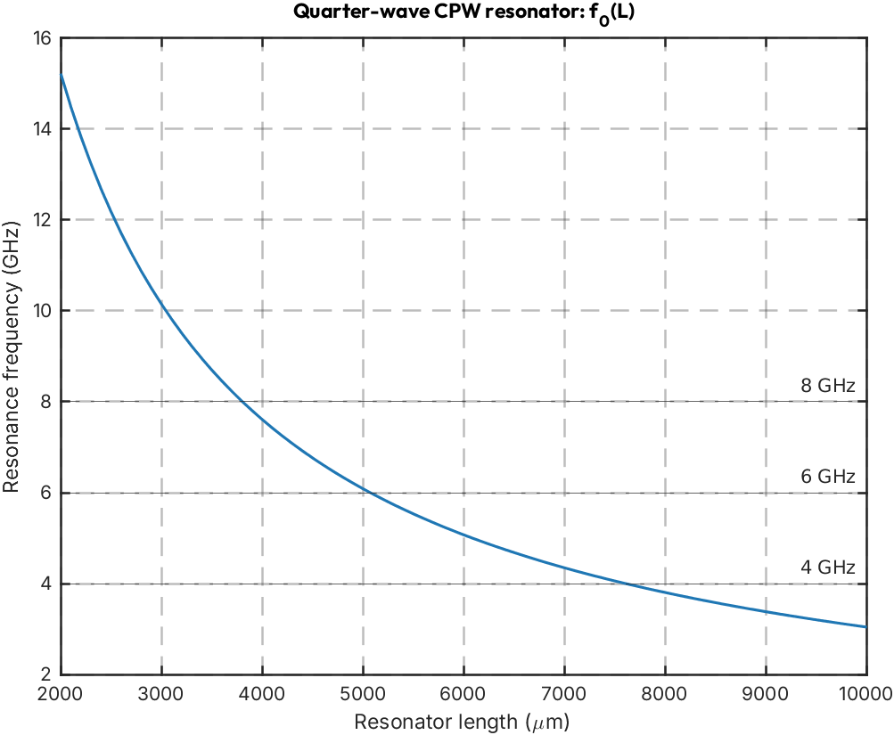
MATLAB drives a linspace of resonator lengths and plots the fundamental frequency. For this
fixed CPW cross-section, the phase velocity is constant and \(f_0\) scales as \(1/L\). One Python
model call sets that scale; MATLAB evaluates the whole sweep with element-wise division.
lengths_um = linspace(2000, 10000, 81);
reference_freq_hz = double(py.qpdk.models.resonator.resonator_frequency( ...
    pyargs('length', lengths_um(1), 'is_quarter_wave', true)));
freqs_hz = reference_freq_hz * lengths_um(1) ./ lengths_um;

figure;
plot(lengths_um, freqs_hz / 1e9, 'LineWidth', 1.5); grid on;
xlabel('Resonator length (\mum)');
ylabel('Resonance frequency (GHz)');
title('Quarter-wave CPW resonator: f_0(L)', 'FontName', 'Outfit');
hold on;
for f = [4 6 8]
    yline(f, '--', sprintf('%d GHz', f));
end
hold off;
Warning: MATLAB has disabled some advanced graphics rendering features by switching to software OpenGL. For more information, click <a href="matlab:opengl('problems')">here</a>.
Inverse design with MATLAB’s fzero#
Use MATLAB’s built-in root finder to invert the analytical model: for each target frequency, find
the resonator length that hits it, then build the corresponding resonator_coupled cell and write
the GDS. Combining MATLAB’s optimisation built-ins with qpdk’s physics models is the most direct
value-add of this integration.
target_ghz = [5, 6, 7];
solved_lengths = zeros(size(target_ghz));
for k = 1:numel(target_ghz)
    f_target_hz = target_ghz(k) * 1e9;
    objective = @(L) double(py.qpdk.models.resonator.resonator_frequency( ...
        pyargs('length', L, 'is_quarter_wave', true))) - f_target_hz;
    solved_lengths(k) = fzero(objective, [500, 50000]);

    fprintf('Target %d GHz -> length %.2f um\n', target_ghz(k), solved_lengths(k));

    component_k = py.qpdk.cells.resonator_coupled( ...
        pyargs('length', solved_lengths(k)));
    out_path = fullfile(results_dir, sprintf('resonator_%dGHz.gds', target_ghz(k)));
    component_k.write_gds(out_path);
end
Target 5 GHz -> length 6086.51 um
Target 6 GHz -> length 5072.09 um
Target 7 GHz -> length 4347.51 um
Parametric chip variants#
Build a 2-D ndgrid of (coupling gap, resonator length) and call
qpdk.samples.resonator_test_chip.resonator_test_chip_python for each combination. Collect
bounding-box areas in a MATLAB table for inspection.
gaps_um = [12, 16, 20];
res_lengths_um = [3500, 4500];
[GG, LL] = ndgrid(gaps_um, res_lengths_um);
n = numel(GG);
areas_mm2 = zeros(n, 1);
files = strings(n, 1);

for k = 1:n
    chip = py.qpdk.samples.resonator_test_chip.resonator_test_chip_python( ...
        pyargs('coupling_gap', GG(k), 'resonator_length', LL(k)));
    sz = chip.size_info;
    w_um = double(sz.width);
    h_um = double(sz.height);
    areas_mm2(k) = (w_um * h_um) / 1e6;
    files(k) = fullfile(results_dir, sprintf('chip_gap%g_len%g.gds', GG(k), LL(k)));
    chip.write_gds(files(k));
end

T = table(GG(:), LL(:), areas_mm2, files, ...
    'VariableNames', {'coupling_gap_um', 'resonator_length_um', 'area_mm2', 'gds_file'});
disp(T);
    coupling_gap_um    resonator_length_um    area_mm2                                              gds_file
    _______________    ___________________    ________    _____________________________________________________________________________________________

          12                  3500             31.194     "/tmp/qpdk_matlab_demo/chip_gap12_len3500.gds"
          16                  3500             31.266     "/tmp/qpdk_matlab_demo/chip_gap16_len3500.gds"
          20                  3500             31.338     "/tmp/qpdk_matlab_demo/chip_gap20_len3500.gds"
          12                  4500             31.194     "/tmp/qpdk_matlab_demo/chip_gap12_len4500.gds"
          16                  4500             31.266     "/tmp/qpdk_matlab_demo/chip_gap16_len4500.gds"
          20                  4500             31.338     "/tmp/qpdk_matlab_demo/chip_gap20_len4500.gds"
SAX models as S-parameter boxes in the RF Toolbox#
Everything above treats Python as a function MATLAB calls. The remaining sections treat a qpdk
model as a component: a SAX model is evaluated in Python, exported as a
Touchstone file, and then read back
into MATLAB as an sparameters object or an nport circuit element. From that point the qpdk
physics is an ordinary black box inside MATLAB’s own RF analysis — it cascades with lumped
elements in a circuit, plots on a Smith chart, gets rational-fitted for a transient response,
and can be written back out with rfwrite.
Touchstone avoids manual complex-array marshalling between the two languages and produces a file
that other RF tools can read too. SAX’s write_sdict_touchstone exports model results directly;
read_sdict_touchstone brings a MATLAB-written file back into a SAX S-dictionary.
Export two SAX models to Touchstone#
Two exports, both driven from MATLAB. The frequency grid is built with linspace in MATLAB and
pushed into Python with py.numpy.asarray, so the same vector is used to evaluate the model and
to label the Touchstone file — write_sdict_touchstone rejects a mismatch rather than silently
misaligning the sweep.
A coplanar-waveguide
straight, at 1 mm and 2 mm, is a two-port:.s2p.quarter_wave_resonator_coupledis a three-port (through line plus the resonator’s own open end):.s3p.
freq_matlab = linspace(4e9, 9e9, 1001);
freq_py = py.numpy.asarray(freq_matlab);

s2p_1mm = fullfile(results_dir, 'cpw_1mm.s2p');
s2p_2mm = fullfile(results_dir, 'cpw_2mm.s2p');
sax_mod.write_sdict_touchstone( ...
    py.qpdk.models.waveguides.straight(pyargs('f', freq_py, 'length', 1000)), ...
    freq_py, s2p_1mm);
sax_mod.write_sdict_touchstone( ...
    py.qpdk.models.waveguides.straight(pyargs('f', freq_py, 'length', 2000)), ...
    freq_py, s2p_2mm);

% The resonator notch is only ~18 MHz wide, so it gets its own finer grid over a narrower span.
freq_res = linspace(6.5e9, 8.0e9, 3001);
freq_res_py = py.numpy.asarray(freq_res);
s3p_res = fullfile(results_dir, 'resonator_coupled.s3p');
sax_mod.write_sdict_touchstone( ...
    py.qpdk.models.resonator.quarter_wave_resonator_coupled(pyargs( ...
        'f', freq_res_py, 'length', 4000, ...
        'coupling_gap', 4.0, 'coupling_straight_length', 400.0)), ...
    freq_res_py, s3p_res);

fprintf('Wrote %s\n', s2p_1mm);
fprintf('Wrote %s\n', s2p_2mm);
fprintf('Wrote %s\n', s3p_res);
Wrote /tmp/qpdk_matlab_demo/cpw_1mm.s2p
Wrote /tmp/qpdk_matlab_demo/cpw_2mm.s2p
Wrote /tmp/qpdk_matlab_demo/resonator_coupled.s3p
Is the RF Toolbox available?#
The sections below need the RF Toolbox, which the notebook may not have — most notably in CI,
where the licence granted to open-source GitHub projects is limited. Rather than fail, detect it
once and guard each subsequent cell with if has_rf.
Three independent checks, because they fail in different ways: QPDK_SKIP_RF_TOOLBOX is the
explicit opt-out for CI, ver/license cover an installation that is absent or unlicensed, and
the trial sparameters call catches the case where the toolbox is installed but a licence cannot
actually be checked out at run time.
rf_env = getenv('QPDK_SKIP_RF_TOOLBOX');
rf_skipped_by_env = ~isempty(rf_env) && ...
    ~ismember(lower(string(rf_env)), ["0", "false", "no", ""]);

has_rf = ~rf_skipped_by_env && ~isempty(ver('rf')) && license('test', 'RF_Toolbox') == 1;
if has_rf
    try
        sparameters(zeros(2, 2, 2), [4e9, 8e9]);
    catch
        has_rf = false;
    end
end

if rf_skipped_by_env
    fprintf('RF Toolbox sections skipped: QPDK_SKIP_RF_TOOLBOX=%s\n', rf_env);
elseif ~has_rf
    fprintf('RF Toolbox sections skipped: toolbox not installed or no licence available.\n');
else
    fprintf('RF Toolbox available; running the S-parameter sections.\n');
end
RF Toolbox available; running the S-parameter sections.
The resonator: three ports down to two, and a Smith chart#
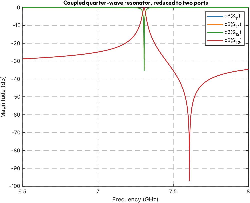
quarter_wave_resonator_coupled exports three ports, but the third is the resonator’s own open
end — it is decoupled from the feedline in this model, so terminating it does not change the
through response. snp2smp performs the reduction, keeping ports 1 and 2 and terminating the rest
in 50 Ω.
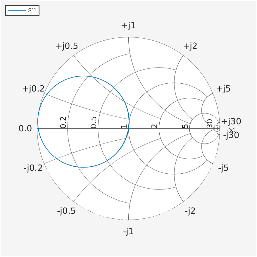
smithplot then shows the reflection \(S_{11}\) traced on the Smith chart: the loop it makes is the
resonance, and the notch in \(S_{21}\) is the same feature viewed in magnitude.
if has_rf
    S_res3 = sparameters(s3p_res);
    coupling_to_port3 = max(abs(S_res3.Parameters(1, 3, :)));
    fprintf('Max |S13| = %.2e (port 3 is the decoupled open end)\n', coupling_to_port3);

    s2 = snp2smp(S_res3.Parameters, S_res3.Impedance, [1 2], 50);
    S_res2 = sparameters(s2, S_res3.Frequencies, S_res3.Impedance);

    s21 = rfparam(S_res2, 2, 1);
    [notch_db, idx] = min(20 * log10(abs(s21)));
    fprintf('Notch: %.1f dB at %.4f GHz\n', notch_db, S_res2.Frequencies(idx) / 1e9);

    figure;
    rfplot(S_res2);
    title('Coupled quarter-wave resonator, reduced to two ports', 'FontName', 'Outfit');

    figure;
    smithplot(S_res2, 1, 1);
    title('S_{11} on the Smith chart', 'FontName', 'Outfit');
end
Max |S13| = 0.00e+00 (port 3 is the decoupled open end)
Notch: -35.4 dB at 7.3070 GHz
Cascading SAX boxes in a MATLAB circuit#
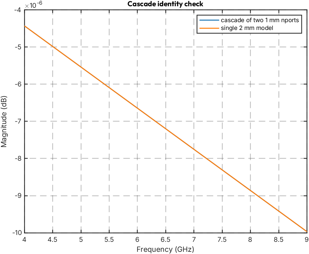
nport wraps a Touchstone file as a circuit element, so a qpdk model can sit inside a MATLAB
netlist alongside anything else the toolbox provides. Two 1 mm lines in series must reproduce the
2 mm line — a cheap end-to-end check that the export, the import, and MATLAB’s cascade all agree
with the analytical model.
if has_rf
    ckt = circuit('cpw_cascade');
    add(ckt, [1 2], nport(s2p_1mm, 'cpw_a'));
    add(ckt, [2 3], nport(s2p_1mm, 'cpw_b'));
    setports(ckt, [1 0], [3 0]);

    S_cascade = sparameters(ckt, freq_matlab);
    S_direct = sparameters(s2p_2mm);

    err_db = max(abs(20 * log10(abs(rfparam(S_cascade, 2, 1))) - ...
        20 * log10(abs(rfparam(S_direct, 2, 1)))));
    fprintf('1 mm + 1 mm vs. 2 mm: max |S21| difference %.2e dB\n', err_db);

    figure;
    rfplot(S_cascade, 2, 1); hold on;
    rfplot(S_direct, 2, 1); hold off;
    legend('cascade of two 1 mm nports', 'single 2 mm model');
    title('Cascade identity check', 'FontName', 'Outfit');
end
1 mm + 1 mm vs. 2 mm: max |S21| difference 1.55e-13 dB
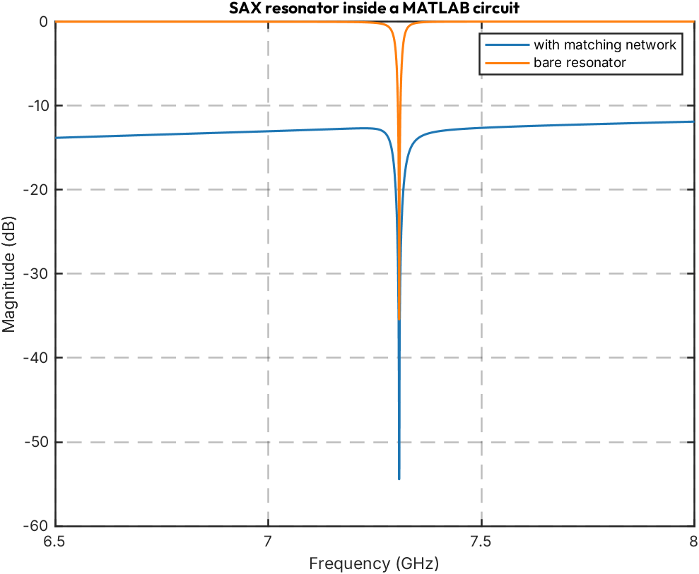
A hybrid circuit: SAX physics plus lumped MATLAB elements#
The point of the nport wrapper is that the qpdk model composes with components qpdk knows
nothing about. Here the resonator is fed through a coupling capacitor and shunted by an inductor —
a crude matching network, built entirely with RF Toolbox primitives around the imported box.
if has_rf
    ckt2 = circuit('resonator_matched');
    add(ckt2, [1 2], capacitor(50e-15, 'c_couple'));
    add(ckt2, [2 3], nport(S_res2, 'sax_resonator'));
    add(ckt2, [3 0], inductor(2.5e-9, 'l_shunt'));
    setports(ckt2, [1 0], [3 0]);

    S_hybrid = sparameters(ckt2, freq_res);

    figure;
    rfplot(S_hybrid, 2, 1); hold on;
    rfplot(S_res2, 2, 1); hold off;
    legend('with matching network', 'bare resonator');
    title('SAX resonator inside a MATLAB circuit', 'FontName', 'Outfit');
end
Rational fitting and transient response#
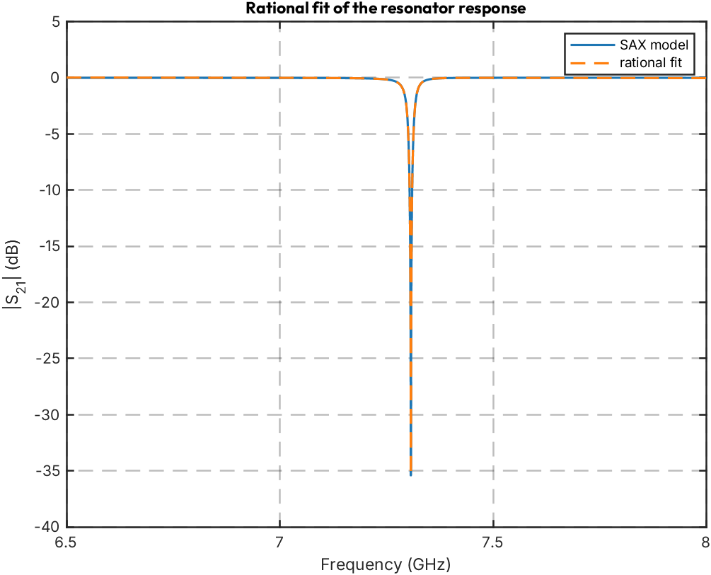
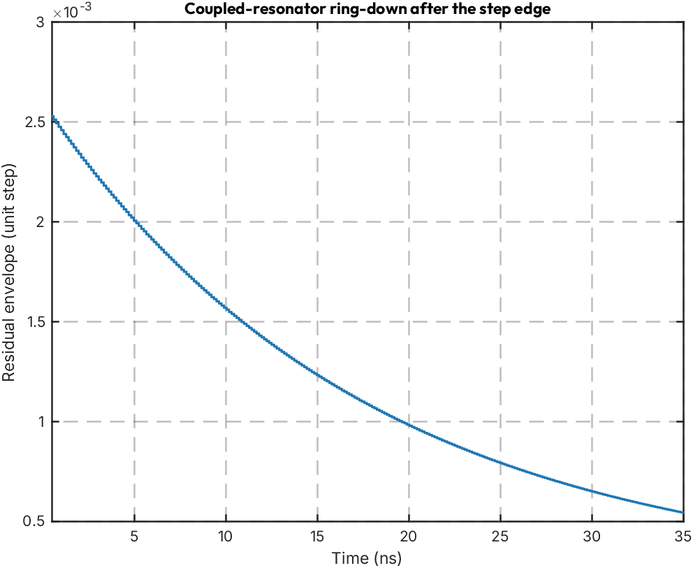
rationalfit turns the sampled \(S_{21}\) into a pole-residue model; freqresp checks the fit
against the sampled data and stepresp
propagates a step edge through it. The prompt feedline response dominates the raw step plot. The
resonator also stores energy and re-radiates it into the feedline; after the edge, its smaller
oscillatory contribution decays on a scale set by the loaded quality factor, approximately
\(\tau_\text{amp} = 2Q_\text{L}/\omega_0\). We subtract the final level and plot the residual
envelope to make that ring-down visible. This is a qualitative transient of a fit over the
measured band, not a calibrated DC-to-microwave step response. The decay rate is related to the
loaded quality factor [GMB+15].
if has_rf
    [fit_s21, errdb] = rationalfit(S_res2.Frequencies, rfparam(S_res2, 2, 1));
    fprintf('Rational fit: %d poles, error %.2f dB\n', numel(fit_s21.A), errdb);

    resp = freqresp(fit_s21, S_res2.Frequencies);
    figure;
    plot(S_res2.Frequencies / 1e9, 20 * log10(abs(rfparam(S_res2, 2, 1))), 'LineWidth', 1.5);
    hold on;
    plot(S_res2.Frequencies / 1e9, 20 * log10(abs(resp)), '--', 'LineWidth', 1.5);
    hold off; grid on;
    xlabel('Frequency (GHz)'); ylabel('|S_{21}| (dB)');
    legend('SAX model', 'rational fit');
    title('Rational fit of the resonator response', 'FontName', 'Outfit');

    [step_out, t_step] = stepresp(fit_s21, 2e-12, 20000, 20e-12);
    ring = step_out - step_out(end);
    period_samples = max(1, round(1 / (S_res2.Frequencies(idx) * (t_step(2) - t_step(1)))));
    envelope = movmax(abs(ring), period_samples);
    figure;
    plot(t_step * 1e9, envelope); grid on;
    xlim([0.5 35]);
    xlabel('Time (ns)'); ylabel('Residual envelope (unit step)');
    title('Coupled-resonator ring-down after the step edge', 'FontName', 'Outfit');
end
Rational fit: 3 poles, error -54.73 dB
Back to Python#
rfwrite exports a MATLAB sparameters object as Touchstone, closing the loop: the hybrid
circuit — part qpdk model, part MATLAB lumped elements — becomes a file that SAX can pick up
again. read_sdict_touchstone is the inverse of the export above; it returns frequencies in Hz
and a SAX SDict, one entry per ordered port pair, ready to drop into a sax.circuit alongside
purely analytical qpdk models.
if has_rf
    hybrid_file = fullfile(results_dir, 'resonator_matched.s2p');
    if isfile(hybrid_file)
        delete(hybrid_file);
    end
    rfwrite(S_hybrid, hybrid_file);

    imported = sax_mod.read_sdict_touchstone(hybrid_file);
    freq_back = double(imported{1});
    sdict_back = imported{2};
    fprintf('Read back into SAX: %d port pairs over %d points (%.2f-%.2f GHz)\n', ...
        int64(py.len(sdict_back)), numel(freq_back), ...
        min(freq_back) / 1e9, max(freq_back) / 1e9);
end
Read back into SAX: 4 port pairs over 3001 points (6.50-8.00 GHz)
Electrostatic FEM of an interdigital capacitor#
Here MATLAB uses qpdk’s interdigital capacitor (IDC) layout and layer stack for a 3D electrostatic solve. The geometry matches the Elmer IDC notebook: four fingers, a grounded M1 frame 10 µm away, a 90 µm lateral pad, and 60 µm of substrate below 40 µm of vacuum.
The solver finds the potential \(\phi\) with \(\nabla \cdot (\epsilon \nabla \phi) = 0\) in the dielectrics. The conductors have fixed potentials; the outer box has natural zero-flux boundaries. For the assembled stiffness matrix \(K\), let \(u_i\) be the nodal solution with terminal \(i\) at 1 V and the other conductors grounded. The discrete field energy gives the Maxwell capacitance matrix [Jin14]:
Its off-diagonal entry is negative: mutual capacitance is \(-C_{12}\), and each terminal’s ground capacitance is its row sum.
The comparison with Elmer has two limits:
The 200 nm Nb film is a zero-thickness sheet, so finger sidewalls are absent.
This study uses quadratic tetrahedra; Elmer uses cubic elements and a finer terminal mesh. Agreement between finite meshes is not an error bound.
This section needs PDE Toolbox and MATLAB R2024a or newer. Set QPDK_SKIP_PDE_TOOLBOX=1 to skip
it; CI does this.
pde_env = getenv('QPDK_SKIP_PDE_TOOLBOX');
pde_skipped_by_env = ~isempty(pde_env) && ...
    ~ismember(lower(string(pde_env)), ["0", "false", "no", ""]);

has_pde = ~pde_skipped_by_env && ~isMATLABReleaseOlderThan("R2024a") && ...
    ~isempty(ver('pde')) && license('test', 'PDE_Toolbox') == 1;
if has_pde
    try
        femodel(AnalysisType="electrostatic");
    catch
        has_pde = false;
    end
end

if pde_skipped_by_env
    fprintf('PDE Toolbox section skipped: QPDK_SKIP_PDE_TOOLBOX=%s\n', pde_env);
elseif ~has_pde
    fprintf('PDE Toolbox section skipped: needs R2024a+ with a licensed PDE Toolbox.\n');
else
    fprintf('PDE Toolbox available; running the electrostatic FEM section.\n');
end
PDE Toolbox available; running the electrostatic FEM section.
Geometry and layer stack from qpdk#
qpdk.simulation.matlab.interdigital_capacitor_fem_geometry returns the two metal outlines in
port order, the layout bounds, and material values from the PDK layer stack. The IDC has no local
etch box so its combs remain separate conductors.
The grounded frame and the domain outline are plain rectangles around the capacitor bounding box. They are drawn in MATLAB with the same offsets that the Elmer notebook uses.
idc_code = strjoin([
    "from qpdk.simulation.matlab import interdigital_capacitor_fem_geometry"
    "combs, bbox, metal_thickness, eps_substrate, eps_vacuum = interdigital_capacitor_fem_geometry("
    "    PDK, fingers=int(fingers), finger_length=finger_length, finger_gap=finger_gap,"
    "    finger_width=finger_width)"
    ], newline);

if has_pde
    [py_combs, py_bbox, metal_thickness, eps_substrate, eps_vacuum] = pyrun(idc_code, ...
        ["combs", "bbox", "metal_thickness", "eps_substrate", "eps_vacuum"], ...
        PDK=PDK, fingers=int32(4), finger_length=20.0, finger_gap=2.0, finger_width=5.0);
    comb_xy = cellfun(@double, cell(py_combs), 'UniformOutput', false);
    idc_bbox = double(py_bbox);
    metal_thickness = double(metal_thickness);
    eps_substrate = double(eps_substrate);
    eps_vacuum = double(eps_vacuum);

    ground_clearance = 10.0;  % um, etched gap from the IDC bounding box to ground
    ground_outer_pad = 45.0;  % um, outer edge of the grounded frame
    domain_pad = 90.0;        % um, lateral extent of the dielectric domain
    substrate_height = 60.0;  % um, truncated from the 500 um PDK substrate
    vacuum_height = 40.0;     % um, truncated from the 500 um PDK vacuum
    grow = @(pad) idc_bbox + [-pad, -pad, pad, pad];
    ground_inner = grow(ground_clearance);
    ground_outer = grow(ground_outer_pad);
    domain_box = grow(domain_pad);

    fprintf('IDC bounding box: (%g, %g) to (%g, %g) um\n', idc_bbox);
    fprintf('Domain: (%g, %g) to (%g, %g) um, z = %+g ... %+g um\n', domain_box, ...
        -substrate_height, vacuum_height);
    fprintf('Substrate eps_r = %.2f, vacuum eps_r = %.2f\n', eps_substrate, eps_vacuum);
    fprintf('M1 film thickness in the PDK: %.3f um (modelled as a sheet)\n', metal_thickness);
end
IDC bounding box: (-18, -13) to (18, 13) um
Domain: (-108, -103) to (108, 103) um, z = -60 ... +40 um
Substrate eps_r = 11.45, vacuum eps_r = 1.00
M1 film thickness in the PDK: 0.200 um (modelled as a sheet)
Build the layered 3D geometry#
decsg combines the domain, ground frame, and two combs while preserving conductor outlines.
extrude places them on the substrate-vacuum interface at \(z=0\). An interior point of each
outline identifies its 3D face with nearestFace.
if has_pde
    rect = @(b) [3; 4; b([1 3 3 1])'; b([2 2 4 4])'];
    n_max = max([8, cellfun(@(xy) 2 + 2 * size(xy, 1), comb_xy)]);
    pad_col = @(col) [col; zeros(n_max - numel(col), 1)];
    shapes = [pad_col(rect(domain_box)), pad_col(rect(ground_outer)), ...
        pad_col(rect(ground_inner))];
    for k = 1:numel(comb_xy)
        xy = comb_xy{k};
        shapes = [shapes, pad_col([2; size(xy, 1); xy(:, 1); xy(:, 2)])]; %#ok<AGROW>
    end
    names = char('D', 'GO', 'GI', 'CA', 'CB')';
    [dl, ~] = decsg(shapes, 'D+(GO-GI)+CA+CB', names);

    gm = fegeometry(dl);
    gm = extrude(gm, [substrate_height, vacuum_height]);
    gm = translate(gm, [0, 0, -substrate_height]);

    interior_point = @(xy) incenter(triangulation(polyshape(xy(:, 1), xy(:, 2))), 1);
    comb_faces = zeros(1, numel(comb_xy));
    for k = 1:numel(comb_xy)
        comb_faces(k) = nearestFace(gm, [interior_point(comb_xy{k}), 0]);
    end
    ground_point = [(ground_outer(1) + ground_inner(1)) / 2, mean(ground_inner([2 4])), 0];
    ground_face = nearestFace(gm, ground_point);

    fprintf('Geometry: %d cells, %d faces\n', gm.NumCells, gm.NumFaces);
    fprintf('Terminal faces: %s, ground face: %d\n', mat2str(comb_faces), ground_face);

end
Geometry: 10 cells, 95 faces
Terminal faces: [8 9], ground face: 7
Solve and extract the capacitance matrix#
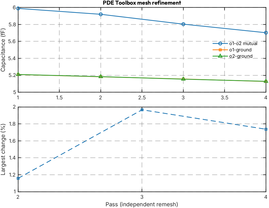
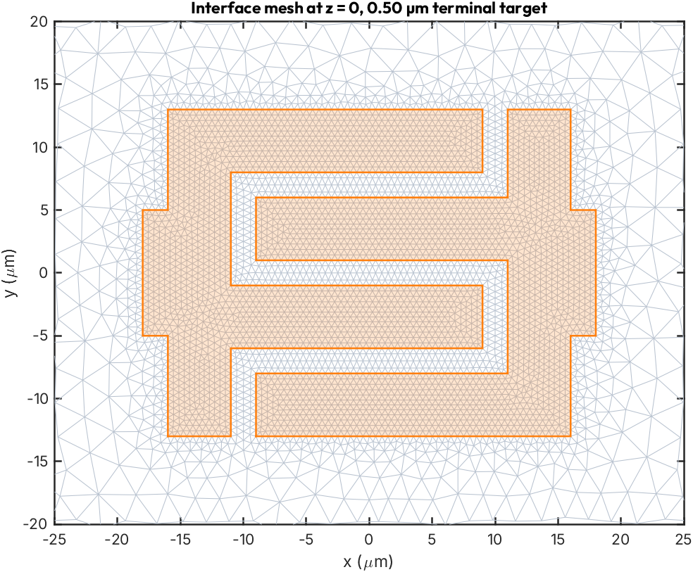
Each pass refines the conductor faces and assembles \(K\) without boundary conditions using
assembleFEMatrices(fem, "none") [MathWorks]. We fix the conductor
nodes and solve \(K_{ff}u_f=-K_{fc}u_c\) for both excitations with one sparse factorisation,
following the standard Dirichlet elimination [Jin14].
VacuumPermittivity=1 leaves only \(\epsilon_\text{r}\) in \(K\); multiplying by
\(\epsilon_0\times10^{-6}\) converts micrometres to farads.
Each pass remeshes independently. The table reports the largest relative change in the mutual and ground capacitances between passes. This is a refinement check, not an absolute error bound.
eps0 = 8.8541878128e-12;  % F/m
um = 1e-6;                % m per geometry unit
mesh_lengths_um = struct('max', 20.0, 'terminal', 1.0, 'ground', 3.0);
mesh_factors = [1.25, 1.0, 0.75, 0.5];

if has_pde
    fem = femodel(AnalysisType="electrostatic", Geometry=gm);
    fem.VacuumPermittivity = 1;

    % Conductor membership is decided from coordinates on the z = 0 plane, which does not depend on
    % how decsg and extrude number the faces. The small buffer absorbs round-off for nodes that sit
    % exactly on a metal outline.
    comb_regions = cellfun(@(xy) polybuffer(polyshape(xy(:, 1), xy(:, 2)), 1e-6), comb_xy);
    in_rect = @(x, y, b, tol) x >= b(1) - tol & x <= b(3) + tol & ...
        y >= b(2) - tol & y <= b(4) + tol;

    n_terminals = numel(comb_xy);
    fem_results = struct('factor', {}, 'C_fF', {}, 'n_nodes', {});
    for pass = 1:numel(mesh_factors)
        tic;
        factor = mesh_factors(pass);
        fem = generateMesh(fem, GeometricOrder="quadratic", Hgrad=1.4, ...
            Hmax=mesh_lengths_um.max * factor, ...
            Hface={comb_faces, mesh_lengths_um.terminal * factor, ...
            ground_face, mesh_lengths_um.ground * factor});
        mesh = fem.Geometry.Mesh;
        nodes = mesh.Nodes;

        % Extruding every planar face through both layers makes many cells; classify each by the
        % height of one of its elements.
        for cell_id = 1:gm.NumCells
            elements = findElements(mesh, "region", Cell=cell_id);
            eps_r = eps_vacuum;
            if mean(nodes(3, mesh.Elements(:, elements(1)))) < 0
                eps_r = eps_substrate;
            end
            fem.MaterialProperties(cell_id) = materialProperties(RelativePermittivity=eps_r);
        end
        K = assembleFEMatrices(fem, "none").K;

        x = nodes(1, :)';
        y = nodes(2, :)';
        on_plane = abs(nodes(3, :)') < 1e-6;
        fixed = on_plane & in_rect(x, y, ground_outer, 1e-6) & ...
            ~in_rect(x, y, ground_inner, -1e-6);
        u = zeros(size(nodes, 2), n_terminals);
        for k = 1:n_terminals
            terminal = on_plane & isinterior(comb_regions(k), x, y);
            fixed = fixed | terminal;
            u(terminal, k) = 1;
        end

        u(~fixed, :) = -K(~fixed, ~fixed) \ (K(~fixed, fixed) * u(fixed, :));
        C = full(u' * K * u) * eps0 * um;
        fem_results(pass) = struct('factor', factor, 'C_fF', (C + C') / 2 * 1e15, ...
            'n_nodes', size(nodes, 2));
        fprintf('mesh factor %.2f: %d nodes (%d on conductors), solved in %.1f s\n', ...
            factor, size(nodes, 2), nnz(fixed), toc);
    end

    summary = zeros(numel(fem_results), 3);
    for k = 1:numel(fem_results)
        C = fem_results(k).C_fF;
        summary(k, :) = [-C(1, 2), sum(C(1, :)), sum(C(2, :))];
    end
    max_change = [NaN; max(abs(diff(summary)) ./ summary(1:end - 1, :), [], 2)];

    T_fem = table(mesh_factors(:), [fem_results.n_nodes]', summary(:, 1), summary(:, 2), ...
        summary(:, 3), 100 * max_change, 'VariableNames', {'mesh_factor', 'nodes', ...
        'mutual_fF', 'o1_ground_fF', 'o2_ground_fF', 'max_change_pct'});
    disp(T_fem);

    C_final = fem_results(end).C_fF;
    fprintf('Final Maxwell capacitance matrix (fF):\n');
    fprintf('  [%9.4f %9.4f]\n', C_final');
    fprintf('Mutual capacitance C12_mutual = -C12: %.3f fF\n', -C_final(1, 2));
    fprintf('Terminal o1 to ground: %.3f fF, o2 to ground: %.3f fF\n', ...
        sum(C_final(1, :)), sum(C_final(2, :)));
    fprintf('Matrix asymmetry |C12 - C21| / |C12|: %.1e\n', ...
        abs(C_final(1, 2) - C_final(2, 1)) / abs(C_final(1, 2)));

    elmer_mutual_fF = 5.708;  % saved cubic Elmer result with a 200 nm film
    fprintf('Elmer (200 nm film, cubic elements) mutual: %.3f fF; difference %+.1f %%\n', ...
        elmer_mutual_fF, 100 * (-C_final(1, 2) / elmer_mutual_fF - 1));

    figure;
    tiledlayout(2, 1, TileSpacing='compact', Padding='compact');
    nexttile;
    plot(1:numel(mesh_factors), summary(:, 1), '-o', Color=plot_colors(1, :));
    hold on;
    plot(1:numel(mesh_factors), summary(:, 2), '-s', Color=plot_colors(2, :));
    plot(1:numel(mesh_factors), summary(:, 3), '-^', Color=plot_colors(3, :));
    hold off;
    ylabel('Capacitance (fF)');
    lgd = legend('o1-o2 mutual', 'o1-ground', 'o2-ground', 'Location', 'best');
    lgd.Box = 'off';
    title('PDE Toolbox mesh refinement', 'FontName', 'Outfit');
    nexttile;
    plot(2:numel(mesh_factors), 100 * max_change(2:end), '--s', ...
        Color=plot_colors(1, :));
    xticks(1:numel(mesh_factors));
    xlabel('Pass (independent remesh)'); ylabel('Largest change (%)');

    % The first four entries of each quadratic tetrahedron are its corner nodes.
    corners = mesh.Elements(1:4, :);
    faces = [corners([1 2 3], :), corners([1 2 4], :), ...
        corners([1 3 4], :), corners([2 3 4], :)];
    faces = faces(:, all(on_plane(faces), 1));
    faces = unique(sort(faces, 1)', 'rows');
    centers = (nodes(1:2, faces(:, 1)) + nodes(1:2, faces(:, 2)) + ...
        nodes(1:2, faces(:, 3))) / 3;
    nearby = abs(centers(1, :)) < 25 & abs(centers(2, :)) < 20;

    figure;
    triplot(faces(nearby, :), nodes(1, :), nodes(2, :), ...
        'Color', [0.72 0.76 0.81], 'LineWidth', 0.5);
    hold on;
    for k = 1:numel(comb_xy)
        xy = comb_xy{k};
        patch(xy(:, 1), xy(:, 2), plot_colors(2, :), FaceAlpha=0.2, ...
            EdgeColor=plot_colors(2, :), LineWidth=1.2);
    end
    hold off;
    grid off;
    axis equal; xlim([-25 25]); ylim([-20 20]);
    xlabel('x (\mum)'); ylabel('y (\mum)');
    title(sprintf('Interface mesh at z = 0, %.2f µm terminal target', ...
        mesh_lengths_um.terminal * mesh_factors(end)), 'FontName', 'Outfit');
end
mesh factor 1.25: 95191 nodes (5892 on conductors), solved in 12.7 s
mesh factor 1.00: 130687 nodes (9580 on conductors), solved in 12.8 s
mesh factor 0.75: 204204 nodes (16338 on conductors), solved in 23.7 s
mesh factor 0.50: 454176 nodes (37098 on conductors), solved in 67.8 s
    mesh_factor      nodes       mutual_fF    o1_ground_fF    o2_ground_fF    max_change_pct
    ___________    __________    _________    ____________    ____________    ______________

       1.25             95191      5.989         5.2087          5.2095              NaN
          1        1.3069e+05     5.9196         5.1825          5.1838           1.1579
       0.75         2.042e+05     5.8032         5.1561          5.1541           1.9663
        0.5        4.5418e+05     5.7024          5.127          5.1288           1.7371

Final Maxwell capacitance matrix (fF):
  [  10.8294   -5.7024]
  [  -5.7024   10.8312]
Mutual capacitance C12_mutual = -C12: 5.702 fF
Terminal o1 to ground: 5.127 fF, o2 to ground: 5.129 fF
Matrix asymmetry |C12 - C21| / |C12|: 0.0e+00
Elmer (200 nm film, cubic elements) mutual: 5.708 fF; difference -0.1 %
Potential just above the metal#
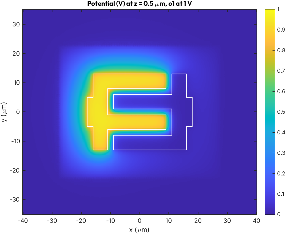
The finest solution with terminal o1 at 1 V, sampled 0.5 µm above the substrate surface. The
field concentrates in the 2 µm finger gaps, which is why the terminal faces carry the finest mesh.
if has_pde
    % nodes and u still hold the finest pass from the loop above.
    near = abs(nodes(3, :)) < 5;
    phi = scatteredInterpolant(nodes(:, near)', u(near, 1), 'linear', 'none');
    [xg, yg] = meshgrid(linspace(-40, 40, 321), linspace(-35, 35, 281));
    phi_grid = phi(xg, yg, 0.5 * ones(size(xg)));

    figure;
    imagesc(xg(1, :), yg(:, 1), phi_grid); axis xy equal tight;
    grid off;
    colorbar; clim([0 1]);
    hold on;
    for k = 1:numel(comb_xy)
        xy = comb_xy{k};
        plot(xy([1:end 1], 1), xy([1:end 1], 2), 'w-', 'LineWidth', 1);
    end
    hold off;
    xlabel('x (\mum)'); ylabel('y (\mum)');
    title('Potential (V) at z = 0.5 \mum, o1 at 1 V', 'FontName', 'Outfit');
end
Joint design targets with the Optimization Toolbox#
The Optimization Toolbox uses lsqnonlin to
find a transmon and resonator design that meets four targets: qubit frequency \(\omega_\text{q}\),
anharmonicity \(\alpha\), resonator frequency \(f_\text{r}\) and dispersive shift \(|\chi|\). The four
unknowns are \(E_\text{J}\), \(E_\text{C}\), the coupling \(g\) and the resonator length.
The closed forms get most of the way. \(\alpha \approx E_\text{C}\) and \(\omega_\text{q} \approx
\sqrt{8E_\text{J}E_\text{C}} - E_\text{C}\) fix the qubit
[KYG+07], fzero fixes the length as above, and
dispersive_shift_to_coupling inverts the rotating-wave approximation for \(g\). That last step is
approximate: dispersive_shift also keeps the counter-rotating terms. lsqnonlin starts from the
closed-form point and solves all four residuals together against the full model, within bounds
that keep every parameter physical.
Without the Optimization Toolbox the closed-form point is kept, so the sections below still have a design to work from.
target = struct('wq_ghz', 5.0, 'alpha_ghz', 0.21, 'fr_ghz', 7.0, 'chi_mhz', 1.0);

resonator_f_ghz = @(L) double(py.qpdk.models.resonator.resonator_frequency( ...
    pyargs('length', L, 'is_quarter_wave', true))) / 1e9;
ec0 = target.alpha_ghz;
ej0 = (target.wq_ghz + ec0)^2 / (8 * ec0);
g0 = as_double(perturbation.dispersive_shift_to_coupling( ...
    -target.chi_mhz * 1e-3, target.wq_ghz, target.fr_ghz, target.alpha_ghz));
length0 = fzero(@(L) resonator_f_ghz(L) - target.fr_ghz, [500, 50000]);
design = struct('ej_ghz', ej0, 'ec_ghz', ec0, 'g_ghz', g0, 'length_um', length0);

if has_toolbox.optim
    % p = [E_J (GHz), E_C (GHz), g (GHz), length (um)]; each residual is a relative error.
    design_residuals = @(p) designResiduals(p, target, perturbation, resonator_f_ghz);
    p0 = [ej0, ec0, g0, length0];
    lb = [5, 0.1, 0.01, 1000];
    ub = [50, 0.4, 0.3, 20000];
    opts = optimoptions("lsqnonlin", Display="final", FunctionTolerance=1e-14, ...
        StepTolerance=1e-12, TypicalX=p0);
    [p_opt, resnorm] = lsqnonlin(design_residuals, p0, lb, ub, opts);
    design = struct('ej_ghz', p_opt(1), 'ec_ghz', p_opt(2), 'g_ghz', p_opt(3), ...
        'length_um', p_opt(4));
    fprintf('Residual norm %.1e\n', resnorm);
    fprintf('g: RWA estimate %.2f MHz -> full model %.2f MHz (%+.1f %%)\n', ...
        1e3 * g0, 1e3 * design.g_ghz, 100 * (design.g_ghz / g0 - 1));
end

% The same models give the circuit values a layout has to realise.
c_sigma_ff = 1e15 * as_double(qubit_models.ec_to_capacitance(design.ec_ghz));
l_j_nh = 1e9 * as_double(qubit_models.ej_to_inductance(design.ej_ghz));
T_design = table(design.ej_ghz, design.ec_ghz, 1e3 * design.g_ghz, design.length_um, ...
    c_sigma_ff, l_j_nh, VariableNames=["EJ_GHz", "EC_GHz", "g_MHz", "length_um", ...
    "C_sigma_fF", "L_J_nH"]);
disp(T_design);

function residuals = designResiduals(p, target, perturbation, resonatorFrequency)
    wq_alpha = perturbation.ej_ec_to_frequency_and_anharmonicity(p(1), p(2));
    wq_ghz = double(py.numpy.asarray(wq_alpha{1}));
    fr_ghz = resonatorFrequency(p(4));
    chi_mhz = 1e3 * abs(double(py.numpy.asarray( ...
        perturbation.dispersive_shift(wq_ghz, fr_ghz, p(2), p(3)))));
    residuals = [(wq_ghz - target.wq_ghz) / target.wq_ghz;
        (p(2) - target.alpha_ghz) / target.alpha_ghz;
        (fr_ghz - target.fr_ghz) / target.fr_ghz;
        (chi_mhz - target.chi_mhz) / target.chi_mhz];
end
Local minimum found.

Optimization completed because the size of the gradient is less than
the value of the optimality tolerance.

Residual norm 1.6e-16
g: RWA estimate 102.59 MHz -> full model 101.07 MHz (-1.5 %)
    EJ_GHz    EC_GHz    g_MHz     length_um    C_sigma_fF    L_J_nH
    ______    ______    ______    _________    __________    ______

    16.157     0.21     101.07     4347.5        92.239      10.117
Fabrication spread with the Statistics and Machine Learning Toolbox#
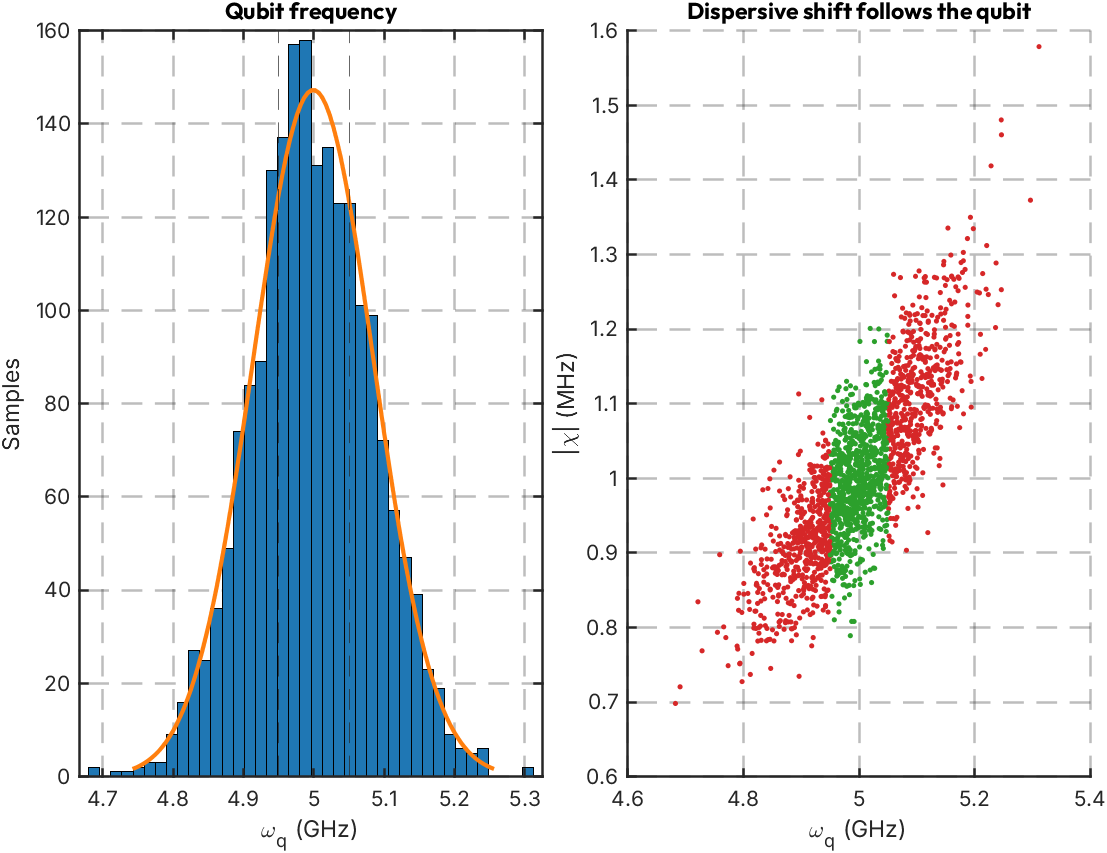
Josephson junctions are the least reproducible part of a transmon: a few per cent spread in normal-state resistance, and so in \(E_\text{J}\), is typical. Island and coupler geometry is better controlled. The spreads below are illustrative rather than taken from a specific process:
\(E_\text{J}\): lognormal, 3 % standard deviation
\(E_\text{C}\) and \(g\): normal, 1.5 % and 3 %
The Statistics and Machine Learning Toolbox
provides the sampling and regression tools. lhsdesign draws a Latin hypercube in the unit cube,
and icdf maps each column onto its distribution. The hypercube covers the tails more evenly than
plain rand at the same sample count. The qpdk models accept NumPy arrays, so all 2000 samples
are evaluated in one Python call per model rather than one call per sample.
fitlm on the standardised inputs then reads off which spread drives \(\omega_\text{q}\) and
\(\chi\). The coefficients are the change in each output per standard deviation of each input.
if has_toolbox.stats
    rng(0);
    n_mc = 2000;
    u_lhs = lhsdesign(n_mc, 3, Criterion="maximin", Iterations=20);
    sigma_ln = 0.03;
    ej_dist = makedist("Lognormal", mu=log(design.ej_ghz) - sigma_ln^2 / 2, sigma=sigma_ln);
    ec_dist = makedist("Normal", mu=design.ec_ghz, sigma=0.015 * design.ec_ghz);
    g_dist = makedist("Normal", mu=design.g_ghz, sigma=0.03 * design.g_ghz);
    ej_mc = icdf(ej_dist, u_lhs(:, 1));
    ec_mc = icdf(ec_dist, u_lhs(:, 2));
    g_mc = icdf(g_dist, u_lhs(:, 3));

    wq_alpha = perturbation.ej_ec_to_frequency_and_anharmonicity(as_numpy(ej_mc), ...
        as_numpy(ec_mc));
    wq_mc = reshape(as_double(wq_alpha{1}), [], 1);
    chi_mc = reshape(1e3 * abs(as_double(perturbation.dispersive_shift(wq_alpha{1}, ...
        target.fr_ghz, wq_alpha{2}, as_numpy(g_mc)))), [], 1);

    tolerance_mhz = 50;
    in_spec = abs(wq_mc - target.wq_ghz) * 1e3 <= tolerance_mhz;
    fprintf('omega_q 5/50/95th percentile: %s GHz\n', mat2str(prctile(wq_mc, [5 50 95]), 4));
    fprintf('|chi|   5/50/95th percentile: %s MHz\n', mat2str(prctile(chi_mc, [5 50 95]), 3));
    fprintf('Within +/-%d MHz of the target qubit frequency: %.1f %%\n', tolerance_mhz, ...
        100 * mean(in_spec));

    mc_inputs = table(zscore(ej_mc), zscore(ec_mc), zscore(g_mc), ...
        VariableNames=["EJ", "EC", "g"]);
    mdl_wq = fitlm([mc_inputs, table(1e3 * wq_mc, VariableNames="wq_MHz")]);
    mdl_chi = fitlm([mc_inputs, table(chi_mc, VariableNames="chi_MHz")]);
    T_sens = table(mdl_wq.Coefficients.Estimate(2:end), ...
        mdl_chi.Coefficients.Estimate(2:end), ...
        RowNames=["EJ", "EC", "g"], ...
        VariableNames=["d_wq_MHz_per_sigma", "d_chi_MHz_per_sigma"]);
    disp(T_sens);
    fprintf('Linear fit R^2: omega_q %.4f, |chi| %.4f\n', mdl_wq.Rsquared.Ordinary, ...
        mdl_chi.Rsquared.Ordinary);

    figure;
    tiledlayout(1, 2, TileSpacing='compact', Padding='compact');
    nexttile;
    histfit(wq_mc, 40, 'normal');
    xline(target.wq_ghz + [-1 1] * tolerance_mhz / 1e3, '--');
    xlabel('\omega_q (GHz)'); ylabel('Samples');
    title('Qubit frequency', 'FontName', 'Outfit');
    nexttile;
    scatter(wq_mc, chi_mc, 6, double(in_spec), 'filled');
    colormap(gca, plot_colors([4 3], :));
    xlabel('\omega_q (GHz)'); ylabel('|\chi| (MHz)');
    title('Dispersive shift follows the qubit', 'FontName', 'Outfit');
end
omega_q 5/50/95th percentile: [4.859 4.996 5.141] GHz
|chi|   5/50/95th percentile: [0.844 0.997 1.19] MHz
Within +/-50 MHz of the target qubit frequency: 43.9 %
          d_wq_MHz_per_sigma    d_chi_MHz_per_sigma
          __________________    ___________________

    EJ           78.103              0.073008
    EC            35.92              0.046999
    g         -0.014507              0.060569

Linear fit R^2: omega_q 0.9999, |chi| 0.9917
Readout speed against Purcell decay with the Global Optimization Toolbox#
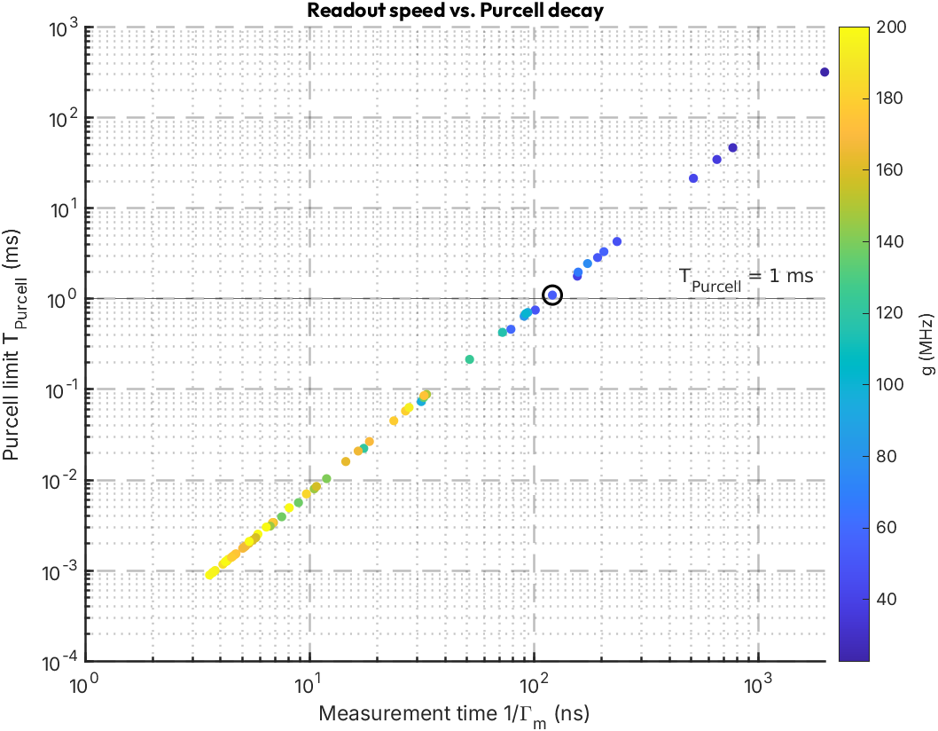
Faster readout and a longer qubit lifetime pull the resonator design in opposite directions. A
larger coupling \(g\) and a broader resonator linewidth \(\kappa\) measure faster but also let the
qubit decay through the resonator, at the Purcell rate \(\gamma = \kappa (g/\Delta)^2\)
[BGGW21]. There is no single optimum, only a trade-off
curve, which paretosearch from the Global Optimization
Toolbox returns.
The decision variables are \(g\), \(f_\text{r}\) and the ratio \(r = \kappa / 2|\chi|\). Parametrising \(\kappa\) through \(r\) keeps every candidate near the \(\kappa \approx 2|\chi|\) point that maximises readout signal-to-noise, using bounds alone and no nonlinear constraint. The two objectives are the Purcell rate and the negative measurement rate \(8\chi^2\bar{n}/\kappa\) at \(\bar{n}=5\) photons [GBS+06]. That expression is the \(|\chi| \ll \kappa\) limit, so it overstates the rate for \(r\) near 1; read the front as a comparison between designs, not as absolute readout times.
UseVectorized hands the objective a whole batch of candidates. Each Python model evaluates the
batch in one call; the objective reuses the dispersive shift for both decay rates.
if has_toolbox.gads
    wq_ghz = as_double(tuple_item(perturbation.ej_ec_to_frequency_and_anharmonicity( ...
        design.ej_ghz, design.ec_ghz), 1));
    alpha_ghz = design.ec_ghz;
    n_bar = 5;
    % x = [g (GHz), f_r (GHz), r]; one row per candidate.
    chi_of = @(x) as_double(perturbation.dispersive_shift(wq_ghz, as_numpy(x(:, 2)), ...
        alpha_ghz, as_numpy(x(:, 1))));
    kappa_of = @(x) 2 * x(:, 3) .* abs(reshape(chi_of(x), [], 1));
    readout_objectives = @(x) readoutObjectives(x, perturbation, wq_ghz, alpha_ghz, n_bar);

    lb = [0.02, 6.0, 1.0];
    ub = [0.20, 8.0, 4.0];
    rng(0);
    opts = optimoptions("paretosearch", UseVectorized=true, ParetoSetSize=60, Display="off");
    [x_front, f_front] = paretosearch(readout_objectives, 3, [], [], [], [], lb, ub, [], opts);

    t_purcell_us = 1 ./ (f_front(:, 1) * 1e9) * 1e6;
    t_meas_ns = 1 ./ (-f_front(:, 2) * 1e9) * 1e9;
    fprintf('Pareto front: %d designs, T_Purcell %.0f-%.0f us, 1/Gamma_m %.1f-%.1f ns\n', ...
        size(x_front, 1), min(t_purcell_us), max(t_purcell_us), min(t_meas_ns), ...
        max(t_meas_ns));

    % Pick the fastest design that still leaves the Purcell limit above 1 ms, then size it.
    candidates = find(t_purcell_us >= 1000);
    if isempty(candidates)
        fprintf('No design on the front reaches T_Purcell >= 1 ms with these bounds.\n');
    else
        [~, best] = min(t_meas_ns(candidates));
        pick = candidates(best);
        x_pick = x_front(pick, :);
        kappa_pick = kappa_of(x_pick);
        length_pick = fzero(@(L) resonator_f_ghz(L) - x_pick(2), [500, 50000]);
        fprintf(['Chosen: g = %.1f MHz, f_r = %.3f GHz, kappa = %.2f MHz (Q_ext = %.0f), ', ...
            'length = %.1f um\n'], 1e3 * x_pick(1), x_pick(2), 1e3 * kappa_pick, ...
            x_pick(2) / kappa_pick, length_pick);
        fprintf('  T_Purcell = %.0f us, 1/Gamma_m = %.1f ns\n', t_purcell_us(pick), ...
            t_meas_ns(pick));
    end

    figure;
    scatter(t_meas_ns, t_purcell_us / 1e3, 24, x_front(:, 1) * 1e3, 'filled');
    set(gca, 'XScale', 'log', 'YScale', 'log');
    cb = colorbar; cb.Label.String = 'g (MHz)';
    if ~isempty(candidates)
        hold on;
        plot(t_meas_ns(pick), t_purcell_us(pick) / 1e3, 'ko', 'MarkerSize', 10);
        hold off;
    end
    yline(1, '--', 'T_{Purcell} = 1 ms');
    xlabel('Measurement time 1/\Gamma_m (ns)'); ylabel('Purcell limit T_{Purcell} (ms)');
    title('Readout speed vs. Purcell decay', 'FontName', 'Outfit');
end

function objectives = readoutObjectives(x, perturbation, wq_ghz, alpha_ghz, n_bar)
    g_py = py.numpy.asarray(x(:, 1).');
    fr_py = py.numpy.asarray(x(:, 2).');
    chi_py = perturbation.dispersive_shift(wq_ghz, fr_py, alpha_ghz, g_py);
    chi_ghz = reshape(double(py.numpy.asarray(chi_py)), [], 1);
    kappa_ghz = 2 * x(:, 3) .* abs(chi_ghz);
    kappa_py = py.numpy.asarray(kappa_ghz.');
    purcell_py = perturbation.purcell_decay_rate(g_py, wq_ghz, fr_py, kappa_py);
    dephasing_py = perturbation.measurement_induced_dephasing(chi_py, kappa_py, n_bar);
    objectives = [reshape(double(py.numpy.asarray(purcell_py)), [], 1), ...
        -reshape(double(py.numpy.asarray(dephasing_py)), [], 1)];
end
Pareto front: 60 designs, T_Purcell 1-319173 us, 1/Gamma_m 3.6-1966.6 ns
Chosen: g = 53.8 MHz, f_r = 6.625 GHz, kappa = 0.83 MHz (Q_ext = 7968), length = 4593.6 um
  T_Purcell = 1099 us, 1/Gamma_m = 120.3 ns
Layout variants with the Parallel Computing Toolbox#
The Parallel Computing Toolbox
provides parfor for independent layout builds. It spreads the GDS builds from the
parametric-variants section over a pool of worker processes.
Each worker runs its own MATLAB with its own Python, so the interpreter has to be selected and the
PDK activated once per worker with parfevalOnAll before the loop. Python objects cannot cross
between workers and the client, so each iteration builds its chip, writes the GDS on the worker
and returns only plain MATLAB numbers. Thread-based pools (parpool('Threads')) cannot call
Python at all, so an existing thread pool is replaced. The example creates at most four workers
and closes its own pool even if a build fails. Setup is timed separately from the builds; a small
grid may finish sooner serially when worker startup is included.
if has_toolbox.parallel
    [GG_par, LL_par] = ndgrid([8, 12, 16, 20], [3000, 3500, 4000, 4500]);
    disp(buildChipVariants(qpdk_python, results_dir, GG_par, LL_par));
end

function variants = buildChipVariants(qpdk_python, results_dir, GG_par, LL_par)
    setup_timer = tic;
    pool = gcp("nocreate");
    if isa(pool, "parallel.ThreadPool")
        fprintf('Replacing thread pool: Python needs process workers.\n');
        delete(pool);
        pool = [];
    end
    if isempty(pool)
        local_cluster = parcluster("Processes");
        pool = parpool(local_cluster, min(4, local_cluster.NumWorkers));
        pool_cleanup = onCleanup(@() delete(pool));
    end
    fetchOutputs(parfevalOnAll(pool, @pyenv, 0, Version=qpdk_python, ...
        ExecutionMode="OutOfProcess"));
    fetchOutputs(parfevalOnAll(pool, @pyrun, 0, "import qpdk; qpdk.PDK.activate()"));
    fprintf('Worker setup: %.1f s\n', toc(setup_timer));

    n_par = numel(GG_par);
    areas_par_mm2 = zeros(n_par, 1);
    build_timer = tic;
    parfor k = 1:n_par
        chip = py.qpdk.samples.resonator_test_chip.resonator_test_chip_python( ...
            pyargs('coupling_gap', GG_par(k), 'resonator_length', LL_par(k)));
        sz = chip.size_info;
        areas_par_mm2(k) = double(sz.width) * double(sz.height) / 1e6;
        chip.write_gds(fullfile(results_dir, ...
            sprintf('par_chip_gap%g_len%g.gds', GG_par(k), LL_par(k))));
    end
    fprintf('Built %d chips on %d workers in %.1f s\n', n_par, pool.NumWorkers, toc(build_timer));
    variants = table(GG_par(:), LL_par(:), areas_par_mm2, ...
        VariableNames=["coupling_gap_um", "resonator_length_um", "area_mm2"]);
end
Replacing thread pool: Python needs process workers.
Parallel pool using the 'Threads' profile is shutting down.
Starting parallel pool (parpool) using the 'Processes' profile ...
Connected to parallel pool with 4 workers.
Worker setup: 45.5 s
Built 16 chips on 4 workers in 4.7 s
Parallel pool using the 'Processes' profile is shutting down.
    coupling_gap_um    resonator_length_um    area_mm2
    _______________    ___________________    ________

           8                  3000             31.122
          12                  3000             31.194
          16                  3000             31.266
          20                  3000             31.338
           8                  3500             31.122
          12                  3500             31.194
          16                  3500             31.266
          20                  3500             31.338
           8                  4000             31.122
          12                  4000             31.194
          16                  4000             31.266
          20                  4000             31.338
           8                  4500             31.122
          12                  4500             31.194
          16                  4500             31.266
          20                  4500             31.338
What’s next#
Open the generated GDS files in KLayout to view the layouts.
Browse the qpdk model catalog for additional analytical models that compose nicely with MATLAB-driven sweeps.
Export any other qpdk model with
sax.write_sdict_touchstoneand drop it into a MATLABcircuitthe same way — the pattern is not specific to the CPW line or the resonator used here.Swap the illustrative fabrication spreads in the Monte Carlo section for measured ones from your own process, or move the design targets and rerun
lsqnonlinandparetosearch.Compare the PDE Toolbox capacitance with the Elmer IDC notebook, or change the
pyrunarguments to extract a different finger count or gap.
References#
assembleFEMatrices: Assemble Finite Element Matrices. MathWorks. URL: https://www.mathworks.com/help/pde/ug/assemblefematrices.html.
Alexandre Blais, Arne L. Grimsmo, S. M. Girvin, and Andreas Wallraff. Circuit quantum electrodynamics. Reviews of Modern Physics, 93(2):025005, May 2021. doi:10.1103/RevModPhys.93.025005.
J. Gambetta, A. Blais, D. I. Schuster, A. Wallraff, L. Frunzio, J. Majer, M. H. Devoret, S. M. Girvin, and R. J. Schoelkopf. Qubit-photon interactions in a cavity: measurement-induced dephasing and number splitting. Physical Review A, 74(4):042318, October 2006. doi:10.1103/PhysRevA.74.042318.
B. Gyüre, B. G. Márkus, B. Bernáth, F. Murányi, and F. Simon. A time domain based method for the accurate measurement of q-factor and resonance frequency of microwave resonators. Review of Scientific Instruments, 86(9):094702, 2015. doi:10.1063/1.4929865.
Jian-Ming Jin. The Finite Element Method in Electromagnetics. Wiley-IEEE Press, 3 edition, 2014. ISBN 978-1-118-57136-1.
Jens Koch, Terri M. Yu, Jay Gambetta, A. A. Houck, D. I. Schuster, J. Majer, Alexandre Blais, M. H. Devoret, S. M. Girvin, and R. J. Schoelkopf. Charge-insensitive qubit design derived from the Cooper pair box. Physical Review A, 76(4):042319, October 2007. doi:10.1103/PhysRevA.76.042319.