Non-manhattan router#
Make sure you review the grid snapping tutorial to understand how to avoid 1nm gaps on your layouts
The non-manhattan (all-angle) router allows you to route between ports and in directions which are not aligned with the x and y axes, which is the constraint of most other gdsfactory routers. Unlike gf.path.smooth() however, the all-angle router:
has a
stepsbased syntax, fully compatible with the yaml-based circuit flowbuilds paths from available PDK components, such that routes can be simulated naturally by S-matrix-based circuit modeling tools, like SAX
allows for advanced logic in selecting appropriate bends, cross-sections, and automatic tapers, based on context
includes advanced cross-section-aware bundling logic
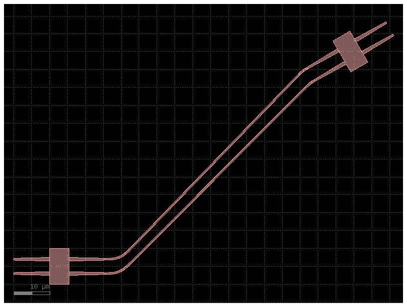
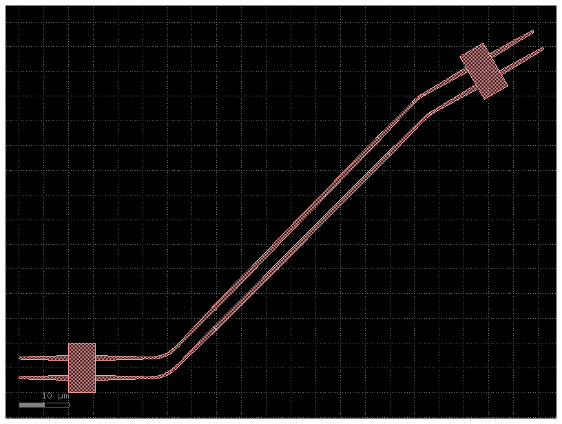
A simple route#
Let’s start with a simple route between two non-orthogonal ports. Consider the yaml-based pic below.
from pathlib import Path
from IPython.display import Code, display

import gdsfactory as gf
from gdsfactory.read import cell_from_yaml_template
from gdsfactory.pdk import get_active_pdk

gf.config.rich_output()
gf.config.enable_off_grid_ports()  # enable off grid ports

pdk = get_active_pdk()
pdk.gds_write_settings.flatten_offgrid_references = True


def show_yaml_pic(filepath):
    cell_name = filepath.stem
    return display(
        Code(filename=filepath, language="yaml+jinja"),
        cell_from_yaml_template(filepath, name=cell_name)(),
    )


# we're going to use yaml-based PICs for our examples. you can find them in docs/notebooks/yaml_pics
# if you'd like to tweak and play along
sample_dir = Path("yaml_pics")

basic_sample_fn = sample_dir / "aar_simple.pic.yml"
show_yaml_pic(basic_sample_fn)
2024-04-27 01:05:22.645 | WARNING | gdsfactory.read.from_yaml:from_yaml:692 - UserWarning: prefix is deprecated and will be removed soon. _from_yaml
instances:
    mmi_long:
      component: mmi1x2
      settings:
        width_mmi: 4.5
        length_mmi: 10
    mmi_short:
      component: mmi1x2
      settings:
        width_mmi: 4.5
        length_mmi: 5

placements:
    mmi_short:
        rotation: 180
    mmi_long:
        port: o1
        rotation: 70  # Look Ma, I'm non-90!
        x: mmi_short,o1
        y: mmi_short,o1
        dx: 20
        dy: 20

routes:
    optical:
        routing_strategy: get_bundle_all_angle # the non-manhattan router
        links:
            mmi_short,o1: mmi_long,o1

ports:
    o1: mmi_short,o2
    o2: mmi_short,o3
2024-04-27 01:05:22.707 | WARNING | gdsfactory.klive:show:49 - UserWarning: Could not connect to klive server. Is klayout open and klive plugin installed?
aar_simple.pic: uid a9f93511, ports ['o1', 'o2'], references ['mmi_long', 'mmi_short', 'straight_1', 'bend_euler_1', 'straight_2'], 0 polygons
You can see that even though one of the ports was non-orthogonal, the route was completed, using non-90-degree bends. The logic of how this works is explained further in the next section
Bends and connectors#
Let’s first consider the “simple” case, as shown above, where the vectors of the two ports to route between intersect at a point. The logic for how to build the route is as follows:
Find the intersection point of the two port vectors.
Place the bend at the intersection point of the two vectors by its “handle”. The bend’s handle is the point of intersetion of it’s inverted port vectors (i.e. if the ports were pointed inwards rather than outwards). For any arbitrary bend, this guarantees that the ports of the bend will be in the straight line of sight of the ports which they should connect to, inset by some amount.
Call the route or segment’s specified connector function to generate a straight section between the bend’s ports and their adjacent ports.
Now, this is where it gets fun. Since we’ve calculated our bend first and worked backwards, we know how much room we have for the straight connector, and we can take that into consideration when creating it.
The three connectors available by default are
low_loss: auto-tapers to the lowest-loss cross-section possible to fit in the given segmentauto_taper: auto-tapers to the cross-section specified, based on the active pdk’s specifiedlayer_transitionssimple: simply routes with a straight in the cross-section specified (no auto-tapering)
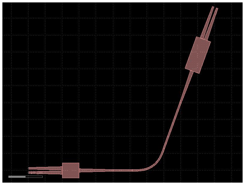
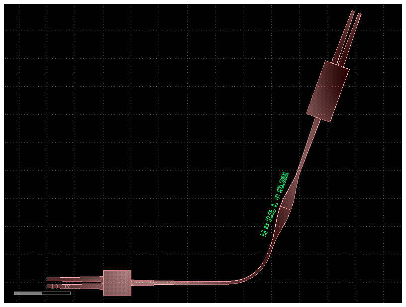
You can also define your own connector, as a function of the two ports which should be connected and the (suggested) cross-section. See the example below, which implements a very custom connector, composed of two sine bends and a physical label.
import numpy as np

import gdsfactory.routing.all_angle as aar


def wonky_connector(port1, port2, cross_section):
    # let's make a wavy-looking connector of two sine tapers, each half the length of the total connector
    # we'll let cross_section define the cross-section at the *center* of the connector here
    connector_length = np.linalg.norm(port2.center - port1.center)
    t1 = (
        gf.components.taper_cross_section_sine(
            length=0.5 * connector_length,
            cross_section1=port1.cross_section,
            cross_section2=cross_section,
        )
        .ref()
        .connect("o1", port1)
    )
    t1.info["length"] = connector_length * 0.5
    t2 = (
        gf.components.taper_cross_section_sine(
            length=0.5 * connector_length,
            cross_section1=port2.cross_section,
            cross_section2=cross_section,
        )
        .ref()
        .connect("o1", port2)
    )
    t2.info["length"] = connector_length * 0.5
    center_port = t1.ports["o2"]
    # just for fun-- we can add a non-functional reference also
    label = gf.components.text(
        f"W = {center_port.width}, L = {connector_length:.3f}",
        size=center_port.width * 0.5,
        justify="center",
        layer="M1",
    ).ref()
    label.move(
        label.center, destination=center_port.center + (0, center_port.width)
    ).rotate(center_port.orientation, center=center_port.center)
    label.info["length"] = 0
    return [t1, t2, label]


# register the connector so it can be used by name
aar.CONNECTORS["wonky"] = wonky_connector

wonky_fn = sample_dir / "aar_wonky_connector.pic.yml"
show_yaml_pic(wonky_fn)
2024-04-27 01:05:23.260 | WARNING | gdsfactory.read.from_yaml:from_yaml:692 - UserWarning: prefix is deprecated and will be removed soon. _from_yaml
instances:
    mmi_long:
      component: mmi1x2
      settings:
        width_mmi: 4.5
        length_mmi: 10
    mmi_short:
      component: mmi1x2
      settings:
        width_mmi: 4.5
        length_mmi: 5

placements:
    mmi_short:
        rotation: 180
    mmi_long:
        port: o1
        rotation: 70
        x: mmi_short,o1
        y: mmi_short,o1
        dx: 20
        dy: 20

routes:
    optical:
        routing_strategy: get_bundle_all_angle
        settings:
          end_connector: wonky  # using our new, wonky connector for the final segment
          end_cross_section:  # and for that final segment, also tip the connector to use this cross-section
            cross_section: xs_sc
            settings:
              width: 2.0
        links:
            mmi_short,o1: mmi_long,o1

ports:
    o1: mmi_short,o2
    o2: mmi_short,o3
2024-04-27 01:05:23.303 | WARNING | gdsfactory.klive:show:49 - UserWarning: Could not connect to klive server. Is klayout open and klive plugin installed?
aar_wonky_connector.pic: uid 5e054b43, ports ['o1', 'o2'], references ['mmi_long', 'mmi_short', 'straight_1', 'bend_euler_1', 'taper_cross_section_1', 'taper_cross_section_2', 'text_1'], 0 polygons
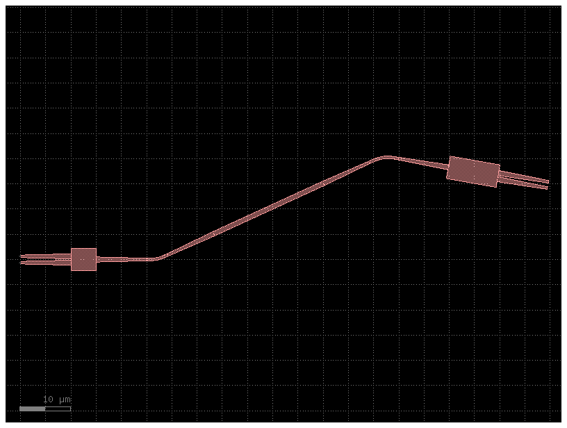
Indirect routes#
Indirect routes are those in which the port vectors do not intersect. In this case, you will see that an S-like bend is created.
indirect_fn = sample_dir / "aar_indirect.pic.yml"
show_yaml_pic(indirect_fn)
instances:
    mmi_long:
      component: mmi1x2
      settings:
        width_mmi: 4.5
        length_mmi: 10
    mmi_short:
      component: mmi1x2
      settings:
        width_mmi: 4.5
        length_mmi: 5

placements:
    mmi_short:
        rotation: 180
    mmi_long:
        port: o1
        rotation: -10  # port vectors no longer intersect
        x: mmi_short,o1
        y: mmi_short,o1
        dx: 50
        dy: 20

routes:
    optical:
        routing_strategy: get_bundle_all_angle
        links:
            mmi_short,o1: mmi_long,o1

ports:
    o1: mmi_short,o2
    o2: mmi_short,o3
aar_indirect.pic: uid 76a8e327, ports ['o1', 'o2'], references ['mmi_long', 'mmi_short', 'bend_euler_1', 'bend_euler_2', 'taper_1', 'straight_1', 'taper_2'], 0 polygons
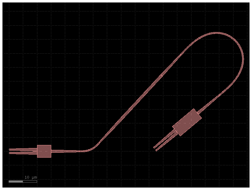
This is also capable of looping around, i.e. for ~180 degree connections.
show_yaml_pic(sample_dir / "aar_around_the_back.pic.yml")
instances:
    mmi_long:
      component: mmi1x2
      settings:
        width_mmi: 4.5
        length_mmi: 10
    mmi_short:
      component: mmi1x2
      settings:
        width_mmi: 4.5
        length_mmi: 5

placements:
    mmi_short:
        rotation: 180
    mmi_long:
        port: o1
        rotation: -140  # ~180 degree connection
        x: mmi_short,o1
        y: mmi_short,o1
        dx: 50
        dy: 20

routes:
    optical:
        routing_strategy: get_bundle_all_angle
        links:
            mmi_short,o1: mmi_long,o1

ports:
    o1: mmi_short,o2
    o2: mmi_short,o3
aar_around_the_back.pic: uid 09ebd462, ports ['o1', 'o2'], references ['mmi_long', 'mmi_short', 'bend_euler_1', 'bend_euler_2', 'taper_1', 'straight_1', 'taper_2'], 0 polygons
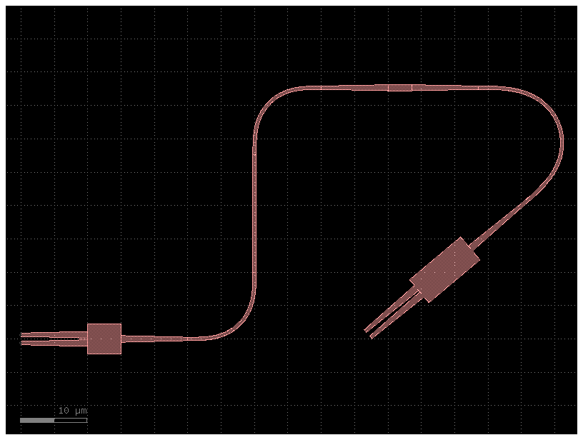
We can fine-tune how this looks by adjusting the start_angle and end_angle of the route, which will abut a bend to the start/end ports such that they exit at the angle specified.
show_yaml_pic(sample_dir / "aar_around_the_back2.pic.yml")
instances:
    mmi_long:
      component: mmi1x2
      settings:
        width_mmi: 4.5
        length_mmi: 10
    mmi_short:
      component: mmi1x2
      settings:
        width_mmi: 4.5
        length_mmi: 5

placements:
    mmi_short:
        rotation: 180
    mmi_long:
        port: o1
        rotation: -140
        x: mmi_short,o1
        y: mmi_short,o1
        dx: 50
        dy: 20

routes:
    optical:
        routing_strategy: get_bundle_all_angle
        settings:
          start_angle: 90  # exit out of the starting port at this angle
          end_angle: 180  # exit out of the ending port at this angle
        links:
            mmi_short,o1: mmi_long,o1

ports:
    o1: mmi_short,o2
    o2: mmi_short,o3
aar_around_the_back2.pic: uid a830acff, ports ['o1', 'o2'], references ['mmi_long', 'mmi_short', 'bend_euler_1', 'bend_euler_2', 'straight_1', 'bend_euler_3', 'taper_1', 'straight_2', 'taper_2'], 0 polygons
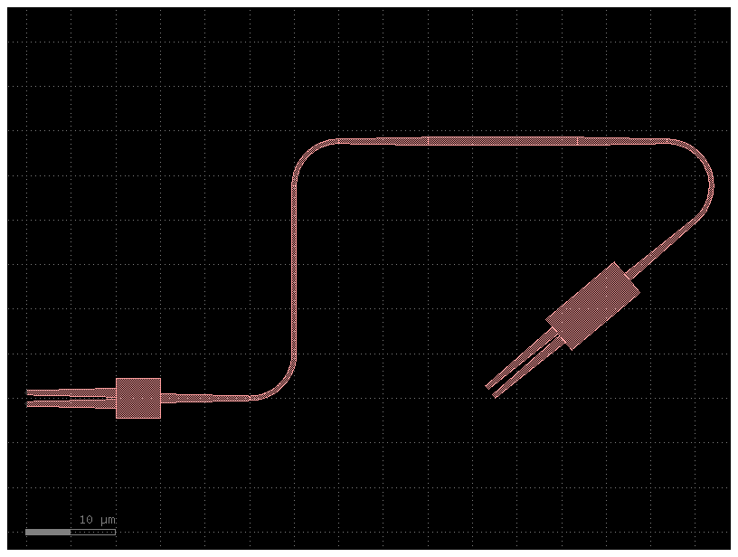
You may also want to further customize the bend used in the route, as shown below.
show_yaml_pic(sample_dir / "aar_around_the_back3.pic.yml")
instances:
    mmi_long:
      component: mmi1x2
      settings:
        width_mmi: 4.5
        length_mmi: 10
    mmi_short:
      component: mmi1x2
      settings:
        width_mmi: 4.5
        length_mmi: 5

placements:
    mmi_short:
        rotation: 180
    mmi_long:
        port: o1
        rotation: -140
        x: mmi_short,o1
        y: mmi_short,o1
        dx: 50
        dy: 20

routes:
    optical:
        routing_strategy: get_bundle_all_angle
        settings:
          bend:  # you can specify a custom bend to use, either by name or with expanded syntax as shown
            component: bend_circular
            settings:
              radius: 5
          start_angle: 90
          end_angle: 180
        links:
            mmi_short,o1: mmi_long,o1

ports:
    o1: mmi_short,o2
    o2: mmi_short,o3
aar_around_the_back3.pic: uid 4acd029e, ports ['o1', 'o2'], references ['mmi_long', 'mmi_short', 'bend_circular_1', 'bend_circular_2', 'straight_1', 'bend_circular_3', 'taper_1', 'straight_2', 'taper_2'], 0 polygons
Steps#
For more complex routes, i.e. when weaving around obstacles, you may want to fine-tune the path that the route traverses. We can do this by defining steps.
show_yaml_pic(sample_dir / "aar_steps01.pic.yml")
instances:
    mmi_long:
      component: mmi1x2
      settings:
        width_mmi: 4.5
        length_mmi: 10
    mmi_short:
      component: mmi1x2
      settings:
        width_mmi: 4.5
        length_mmi: 5
    obstacle1:
      component: rectangle
      settings:
        layer: M1
        size: [30, 30]

placements:
    mmi_short:
        rotation: 180
    mmi_long:
        port: o1
        rotation: 20
        x: mmi_short,o1
        y: mmi_short,o1
        dx: 120
        dy: 80
    obstacle1:
        port: ce
        x: mmi_long,o1
        y: mmi_long,o1
        dx: -20
        dy: -10

routes:
    optical:
        routing_strategy: get_bundle_all_angle
        settings:
          steps:
            - ds: 50  # proceed out of the start port by 50 um
              exit_angle: 90  # then exit at 90 deg
            - ds: 100  # go another 100 um
              exit_angle: 0  # exit at 0 deg
            - ds: 40 # go another 40 um
              exit_angle: -45 # finally, exit at -45 deg (until intersection with final port vector)
        links:
            mmi_short,o1: mmi_long,o1

ports:
    o1: mmi_short,o2
    o2: mmi_short,o3
aar_steps01.pic: uid 24e7b219, ports ['o1', 'o2'], references ['mmi_long', 'mmi_short', 'obstacle1', 'taper_1', 'straight_1', 'taper_2', 'bend_euler_1', 'taper_3', 'straight_2', 'taper_4', 'bend_euler_2', 'taper_5', 'straight_3', 'taper_6', 'bend_euler_3', 'taper_7', 'straight_4', 'taper_8', 'bend_euler_4', 'straight_5'], 0 polygons
There are many different parameters you can put in the step directives. To make a complex route like this, a great way is to first sketch it out with the klayout ruler, then convert it to a set of ds and exit_angle step directives. Combine this with gf watch for live file-watching, and you can quickly iterate to achieve your desired route.
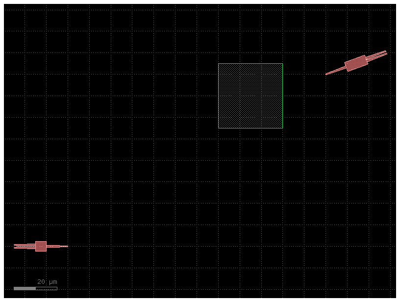
For example, consider the following circuit. Let’s start with the same two MMIs and obstacle as in the previous example.
show_yaml_pic(sample_dir / "aar_steps02_initial.pic.yml")
instances:
    mmi_long:
      component: mmi1x2
      settings:
        width_mmi: 4.5
        length_mmi: 10
    mmi_short:
      component: mmi1x2
      settings:
        width_mmi: 4.5
        length_mmi: 5
    obstacle1:
      component: rectangle
      settings:
        layer: M1
        size: [30, 30]

placements:
    mmi_short:
        rotation: 180
    mmi_long:
        port: o1
        rotation: 20
        x: mmi_short,o1
        y: mmi_short,o1
        dx: 120
        dy: 80
    obstacle1:
        port: ce
        x: mmi_long,o1
        y: mmi_long,o1
        dx: -20
        dy: -10

#routes:
#    optical:
#        routing_strategy: get_bundle_all_angle
#        links:
#            mmi_short,o1: mmi_long,o1

ports:
    o1: mmi_short,o2
    o2: mmi_short,o3
aar_steps02_initial.pic: uid 3149b6be, ports ['o1', 'o2'], references ['mmi_long', 'mmi_short', 'obstacle1'], 0 polygons
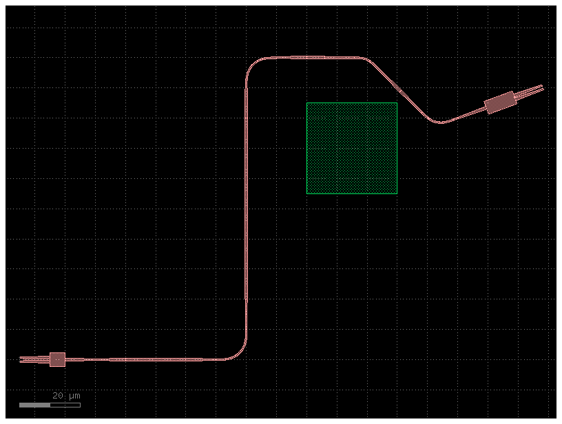
Then, translate the steps you took with the ruler into a set of steps directives.
show_yaml_pic(sample_dir / "aar_steps02_final.pic.yml")
2024-04-27 01:05:25.236 | WARNING | gdsfactory.routing.all_angle:_make_error_trace:204 - RouteWarning: Not enough room to route between ports: {'name': 'o2', 'width': 0.5, 'center': [131.296659, 80.471945], 'orientation': 20.0, 'layer': [1, 0], 'port_type': 'optical'} and {'name': 'o1', 'width': 0.5, 'center': [130.0, 80.0], 'orientation': 200.0, 'layer': [1, 0], 'port_type': 'optical'}
instances:
    mmi_long:
      component: mmi1x2
      settings:
        width_mmi: 4.5
        length_mmi: 10
    mmi_short:
      component: mmi1x2
      settings:
        width_mmi: 4.5
        length_mmi: 5
    obstacle1:
      component: rectangle
      settings:
        layer: M1
        size: [30, 30]

placements:
    mmi_short:
        rotation: 180
    mmi_long:
        port: o1
        rotation: 20
        x: mmi_short,o1
        y: mmi_short,o1
        dx: 120
        dy: 80
    obstacle1:
        port: ce
        x: mmi_long,o1
        y: mmi_long,o1
        dx: -20
        dy: -10

routes:
    optical:
        routing_strategy: get_bundle_all_angle
        settings:
          steps:
            - ds: 65
              exit_angle: 90
            - ds: 110
              exit_angle: 0
            - ds: 81.5
              exit_angle: -65
            - ds: 52
              exit_angle: -158
            - ds: 47.5
              exit_angle: 112
        links:
            mmi_short,o1: mmi_long,o1

ports:
    o1: mmi_short,o2
    o2: mmi_short,o3
aar_steps02_final.pic: uid 0c678ad3, ports ['o1', 'o2'], references ['mmi_long', 'mmi_short', 'obstacle1', 'taper_1', 'straight_1', 'taper_2', 'bend_euler_1', 'taper_3', 'straight_2', 'taper_4', 'bend_euler_2', 'taper_5', 'straight_3', 'taper_6', 'bend_euler_3', 'taper_7', 'straight_4', 'taper_8', 'bend_euler_4', 'taper_9', 'straight_5', 'taper_10', 'bend_euler_5', 'straight_6', 'bend_euler_6', 'extrude_1'], 0 polygons
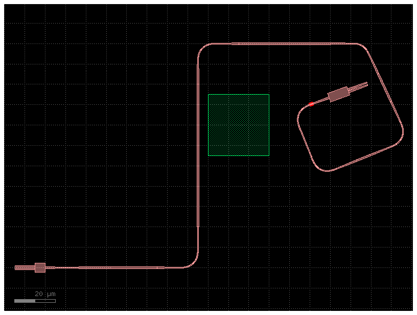
Perfect! Just like we sketched it!
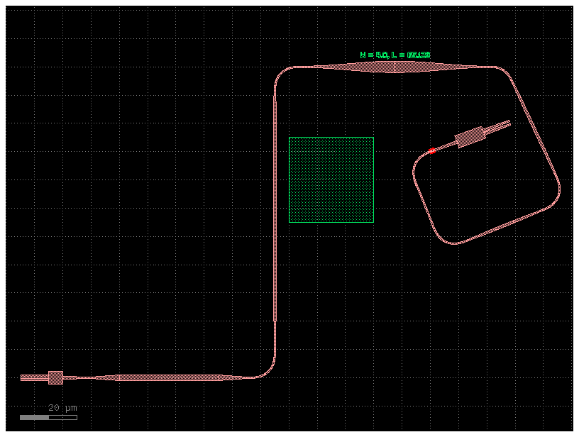
You can also start to customize cross-sections and connectors of individual segments, as shown below.
show_yaml_pic(sample_dir / "aar_steps03.pic.yml")
instances:
    mmi_long:
      component: mmi1x2
      settings:
        width_mmi: 4.5
        length_mmi: 10
    mmi_short:
      component: mmi1x2
      settings:
        width_mmi: 4.5
        length_mmi: 5
    obstacle1:
      component: rectangle
      settings:
        layer: M1
        size: [30, 30]

placements:
    mmi_short:
        rotation: 180
    mmi_long:
        port: o1
        rotation: 20
        x: mmi_short,o1
        y: mmi_short,o1
        dx: 120
        dy: 80
    obstacle1:
        port: ce
        x: mmi_long,o1
        y: mmi_long,o1
        dx: -20
        dy: -10

routes:
    optical:
        routing_strategy: get_bundle_all_angle
        settings:
          steps:
            - ds: 65
              exit_angle: 90
              cross_section:  # set a custom cross-section here...
                cross_section: xs_sc
                settings:
                  width: 2.0
            - ds: 110
              exit_angle: 0
            - ds: 81.5
              exit_angle: -65
              connector: wonky  # let's reuse our wonky connector again here
              cross_section:
                cross_section: xs_sc
                settings:
                  width: 4.0
            - ds: 52
              exit_angle: -158
            - ds: 47.5
              exit_angle: 112
        links:
            mmi_short,o1: mmi_long,o1

ports:
    o1: mmi_short,o2
    o2: mmi_short,o3
aar_steps03.pic: uid 8904cc60, ports ['o1', 'o2'], references ['mmi_long', 'mmi_short', 'obstacle1', 'taper_1', 'taper_2', 'straight_1', 'bend_euler_1', 'taper_3', 'straight_2', 'taper_4', 'bend_euler_2', 'taper_cross_section_1', 'taper_cross_section_2', 'text_1', 'bend_euler_3', 'taper_5', 'straight_3', 'taper_6', 'bend_euler_4', 'taper_7', 'straight_4', 'taper_8', 'bend_euler_5', 'straight_5', 'bend_euler_6', 'extrude_1'], 0 polygons
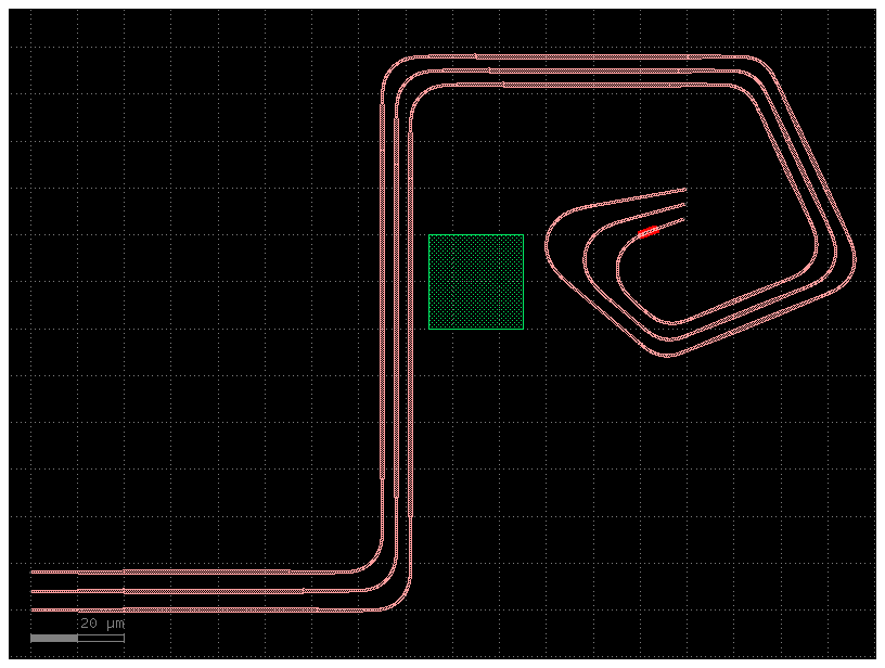
Bundles#
You can also create all-angle bundles.
show_yaml_pic(sample_dir / "aar_bundles01.pic.yml")
2024-04-27 01:05:25.902 | WARNING | gdsfactory.routing.all_angle:_make_error_trace:204 - RouteWarning: Not enough room to route between ports: {'name': 'o2', 'width': 0.5, 'center': [123.501934, 81.2746], 'orientation': 20.0, 'layer': [1, 0], 'port_type': 'optical'} and {'name': 'o1', 'width': 0.5, 'center': [120.0, 80.0], 'orientation': 200.0, 'layer': [1, 0], 'port_type': 'optical'}
default_settings:
  n_bundle:
    value: 3
    description: "The number of routes in the bundle"

instances:
{% for i in range(n_bundle) %}
    wg_start_{{ i }}:
      component: straight
    wg_end_{{ i }}:
      component: straight
{% endfor %}
    obstacle1:
      component: rectangle
      settings:
        layer: M1
        size: [20, 20]

placements:
{% for i in range(n_bundle) %}
    wg_end_{{ i }}:
        rotation: 180
        y: {{ i * 4 }}
    wg_start_{{ i }}:
        port: o1
        rotation: {{ 20 - i * 5 }}  # ports need not be aligned
        x: wg_end_0,o1
        y: wg_end_0,o1
        dx: 120
        dy: {{ 80 + i * 4 }}
{% endfor %}
    obstacle1:
        port: ce
        x: wg_start_0,o1
        y: wg_start_0,o1
        dx: -25
        dy: -10

routes:
    optical:
        routing_strategy: get_bundle_all_angle
        settings:
          separation: 3  # the separation between routes in the bundle. by default uses what is defined in the cross-section
          steps:
            - ds: 65
              exit_angle: 90
            - ds: 110
              exit_angle: 0
            - ds: 81.5
              exit_angle: -65
            - ds: 52
              exit_angle: -158
            - ds: 47.5
              exit_angle: 140
        links:
{% for i in [2, 1, 0] %}
            wg_end_{{ i }},o1: wg_start_{{ i }},o1
{% endfor %}

ports:
    o1: wg_start_0,o2
    o2: wg_end_0,o2
aar_bundles01.pic: uid ff12d7ef, ports ['o1', 'o2'], references ['wg_start_0', 'wg_end_0', 'wg_start_1', 'wg_end_1', 'wg_start_2', 'wg_end_2', 'obstacle1', 'taper_1', 'straight_1', 'taper_2', 'bend_euler_1', 'taper_3', 'straight_2', 'taper_4', 'bend_euler_2', 'taper_5', 'straight_3', 'taper_6', 'bend_euler_3', 'taper_7', 'straight_4', 'taper_8', 'bend_euler_4', 'taper_9', 'straight_5', 'taper_10', 'bend_euler_5', 'straight_6', 'bend_euler_6', 'straight_7', 'taper_11', 'straight_8', 'taper_12', 'bend_euler_7', 'taper_13', 'straight_9', 'taper_14', 'bend_euler_8', 'taper_15', 'straight_10', 'taper_16', 'bend_euler_9', 'taper_17', 'straight_11', 'taper_18', 'bend_euler_10', 'taper_19', 'straight_12', 'taper_20', 'bend_euler_11', 'straight_13', 'bend_euler_12', 'straight_14', 'taper_21', 'straight_15', 'taper_22', 'bend_euler_13', 'taper_23', 'straight_16', 'taper_24', 'bend_euler_14', 'taper_25', 'straight_17', 'taper_26', 'bend_euler_15', 'taper_27', 'straight_18', 'taper_28', 'bend_euler_16', 'taper_29', 'straight_19', 'taper_30', 'bend_euler_17', 'straight_20', 'bend_euler_18', 'extrude_1'], 0 polygons

In addition to the parameters that can be customized for each step of a single route, bundles also let you customize the separation value step-by-step. For example, let’s space out the routes of that top, horizontal segment of the bundle.
show_yaml_pic(sample_dir / "aar_bundles02.pic.yml")
default_settings:
  n_bundle:
    value: 3
    description: "The number of routes in the bundle"

instances:
{% for i in range(n_bundle) %}
    wg_start_{{ i }}:
      component: straight
    wg_end_{{ i }}:
      component: straight
{% endfor %}
    obstacle1:
      component: rectangle
      settings:
        layer: M1
        size: [20, 20]

placements:
{% for i in range(n_bundle) %}
    wg_end_{{ i }}:
        rotation: 180
        y: {{ i * 4 }}
    wg_start_{{ i }}:
        port: o1
        rotation: {{ 20 - i * 5 }}  # ports need not be aligned
        x: wg_end_0,o1
        y: wg_end_0,o1
        dx: 120
        dy: {{ 80 + i * 4 }}
{% endfor %}
    obstacle1:
        port: ce
        x: wg_start_0,o1
        y: wg_start_0,o1
        dx: -25
        dy: -10

routes:
    optical:
        routing_strategy: get_bundle_all_angle
        settings:
          separation: 3
          steps:
            - ds: 65
              exit_angle: 90
            - ds: 110
              exit_angle: 0
            - ds: 81.5
              exit_angle: -65
              separation: 10  # we can customize separation of individual segments of the bundle
            - ds: 52
              exit_angle: -158
            - ds: 47.5
              exit_angle: 140
        links:
{% for i in range(n_bundle-1, -1, -1) %}
            wg_end_{{ i }},o1: wg_start_{{ i }},o1
{% endfor %}

ports:
{% for i in range(n_bundle) %}
    o{{ i }}: wg_start_{{ i }},o2
    o{{ n_bundle + i }}: wg_end_{{ i }},o2
{% endfor %}
aar_bundles02.pic: uid e28d08c5, ports ['o0', 'o3', 'o1', 'o4', 'o2', 'o5'], references ['wg_start_0', 'wg_end_0', 'wg_start_1', 'wg_end_1', 'wg_start_2', 'wg_end_2', 'obstacle1', 'taper_1', 'straight_1', 'taper_2', 'bend_euler_1', 'taper_3', 'straight_2', 'taper_4', 'bend_euler_2', 'taper_5', 'straight_3', 'taper_6', 'bend_euler_3', 'taper_7', 'straight_4', 'taper_8', 'bend_euler_4', 'taper_9', 'straight_5', 'taper_10', 'bend_euler_5', 'straight_6', 'bend_euler_6', 'straight_7', 'taper_11', 'straight_8', 'taper_12', 'bend_euler_7', 'taper_13', 'straight_9', 'taper_14', 'bend_euler_8', 'taper_15', 'straight_10', 'taper_16', 'bend_euler_9', 'taper_17', 'straight_11', 'taper_18', 'bend_euler_10', 'taper_19', 'straight_12', 'taper_20', 'bend_euler_11', 'straight_13', 'bend_euler_12', 'straight_14', 'taper_21', 'straight_15', 'taper_22', 'bend_euler_13', 'taper_23', 'straight_16', 'taper_24', 'bend_euler_14', 'taper_25', 'straight_17', 'taper_26', 'bend_euler_15', 'taper_27', 'straight_18', 'taper_28', 'bend_euler_16', 'taper_29', 'straight_19', 'taper_30', 'bend_euler_17', 'straight_20', 'bend_euler_18', 'extrude_1'], 0 polygons
%%html
<style>
  table {margin-left: 0 !important;}
</style>
Summary of available parameters#
We went through many examples above. Here is a quick recap of the parameters we used for the all-angle router.
Top-level settings#
These settings can be used in the bundle’s top-level settings block and will be applied to the whole bundle, unless overridden by an individual segment.
Name |
Function |
|---|---|
start_angle |
Defines the starting angle of the route (attaches a bend to the starting port to exit at that angle) |
end_angle |
Defines the angle leaving the end port of the route (attaches a bend to the end port to exit at that angle) |
bend |
The default component to use for the bends |
cross_section |
This cross-section will be passed to the bends and the straight connectors. However, these functions can use this information as they like (i.e. an auto-taper connector will attempt to taper to the cross-section but a low-loss connector may ignore it |
end_connector |
Specifies the connector to use for the final straight segment of the route |
end_cross_section |
Specifies the cross-section to use for the final straight segment of the route |
separation |
(bundle only) Specifies the separation between adjacent routes. If |
steps |
A set of directives for custom routing. This is expected to be a list of dictionaries with parameters per step as defined below |
Step directives#
These settings can be defined within individual steps to control the direction of each step.
Please note that an error will be thrown if a step is overconstrained. For example, x and y can be defined together in a single step only if exit_angle is not defined in the previous step. If exit_angle is defined (or angle is otherwise constrained by the port before it), you can only define one of x, y, ds, dx, or dy.
Name |
Function |
|---|---|
x |
Route to the given x coordinate (absolute) |
y |
Route to the given y coordinate (absolute) |
ds |
Proceed in the current orientation by this distance |
dx |
The x-component of distance traveled should be this value |
dy |
The y-component of distance traveled should be this value |
exit_angle |
After this segment, place a bend to exit with this angle (degrees) |
Step customizations#
These settings can also be set on individual steps to customize the route in that segment.
Name |
Function |
|---|---|
cross_section |
Use this cross-section for this segment. Will fall back to an auto-taper connector by default if this is specified alone, without |
connector |
Use this connector for this segment |
separation |
(bundles only) The separation to use between routes of this segment |
Python-based examples#
Most of the above examples were done in yaml syntax. Here are some additional examples creating the routes in pure python.
import gdsfactory as gf

c = gf.Component("demo")

mmi = gf.components.mmi2x2(width_mmi=10, gap_mmi=3)
mmi1 = c << mmi
mmi2 = c << mmi

mmi2.move((100, 10))
mmi2.rotate(30)

routes = gf.routing.get_bundle_all_angle(
    mmi1.get_ports_list(orientation=0),
    [mmi2.ports["o2"], mmi2.ports["o1"]],
    connector=None, # does not taper to wider waveguide
)
for route in routes:
    c.add(route.references)
c.plot()
c = gf.Component("demo")

mmi = gf.components.mmi2x2(width_mmi=10, gap_mmi=3)
mmi1 = c << mmi
mmi2 = c << mmi

mmi2.move((100, 10))
mmi2.rotate(30)

routes = gf.routing.get_bundle_all_angle(
    mmi1.get_ports_list(orientation=0),
    [mmi2.ports["o2"], mmi2.ports["o1"]],
    connector="low_loss", # tapes to wider waveguide waveguides to reduce loss
)
for route in routes:
    c.add(route.references)
c.plot()
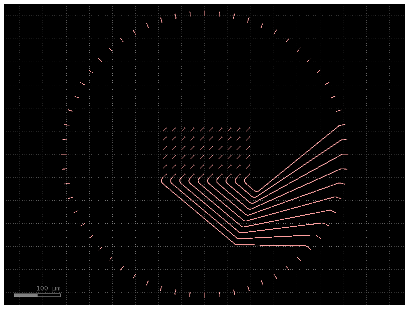
import gdsfactory as gf
from gdsfactory.routing.all_angle import get_bundle_all_angle

NUM_WIRES = 10


@gf.cell
def inner_array():
    c = gf.Component()
    base = gf.components.straight(cross_section=gf.cross_section.strip).rotate(45)
    for x in range(10):
        for y in range(6):
            base_ref = c.add_ref(base).move((x * 20 - 90, y * 20 - 50))
            c.add_port(f"inner_{x}_{y}", port=base_ref.ports["o1"])
    return c


@gf.cell
def outer_array():
    c = gf.Component()
    base = gf.components.straight(cross_section=gf.cross_section.strip)
    for idx, theta in enumerate(range(0, 360, 6)):
        base_ref = c.add_ref(base).move((300, 0)).rotate(theta)
        c.add_port(f"outer_{idx}", port=base_ref.ports["o1"])
    return c


@gf.cell
def chip():
    c = gf.Component()
    inner = c << inner_array()
    outer = c << outer_array()
    inner_ports = inner.get_ports_list()
    outer_ports = outer.get_ports_list()
    for n_route in range(NUM_WIRES):
        routes = get_bundle_all_angle(
            ports1=[inner_ports[n_route]],
            ports2=[outer_ports[n_route]],
            cross_section=gf.cross_section.strip,
            bend=gf.components.bend_euler,
            start_angle=-40,
            steps=[
                {"ds": (NUM_WIRES - n_route) * 20},
            ],
        )
        for route in routes:
            c.add(route.references)
    return c


gf.get_active_pdk().register_cross_sections(strip=gf.cross_section.strip)
c = chip()
c.plot()
2024-04-27 01:05:28.845 | WARNING | gdsfactory.routing.all_angle:_make_error_trace:204 - RouteWarning: Not enough room to route between ports: {'name': 'o2', 'width': 0.9, 'center': [98.303636, -71.159388], 'orientation': 320.0, 'layer': [1, 0], 'port_type': 'optical'} and {'name': 'o2', 'width': 0.9, 'center': [98.303636, -71.159388], 'orientation': 140.0, 'layer': [1, 0], 'port_type': 'optical'}