PCells#
Parametric Cells for the Generic PDK.
Consider them a foundation from which you can draw inspiration. Feel free to modify their cross-sections and layers to tailor a unique PDK suited for any foundry of your choice.
By doing so, you’ll possess a versatile, retargetable PDK, empowering you to design your circuits with speed and flexibility.
components#
analog#
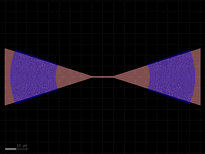
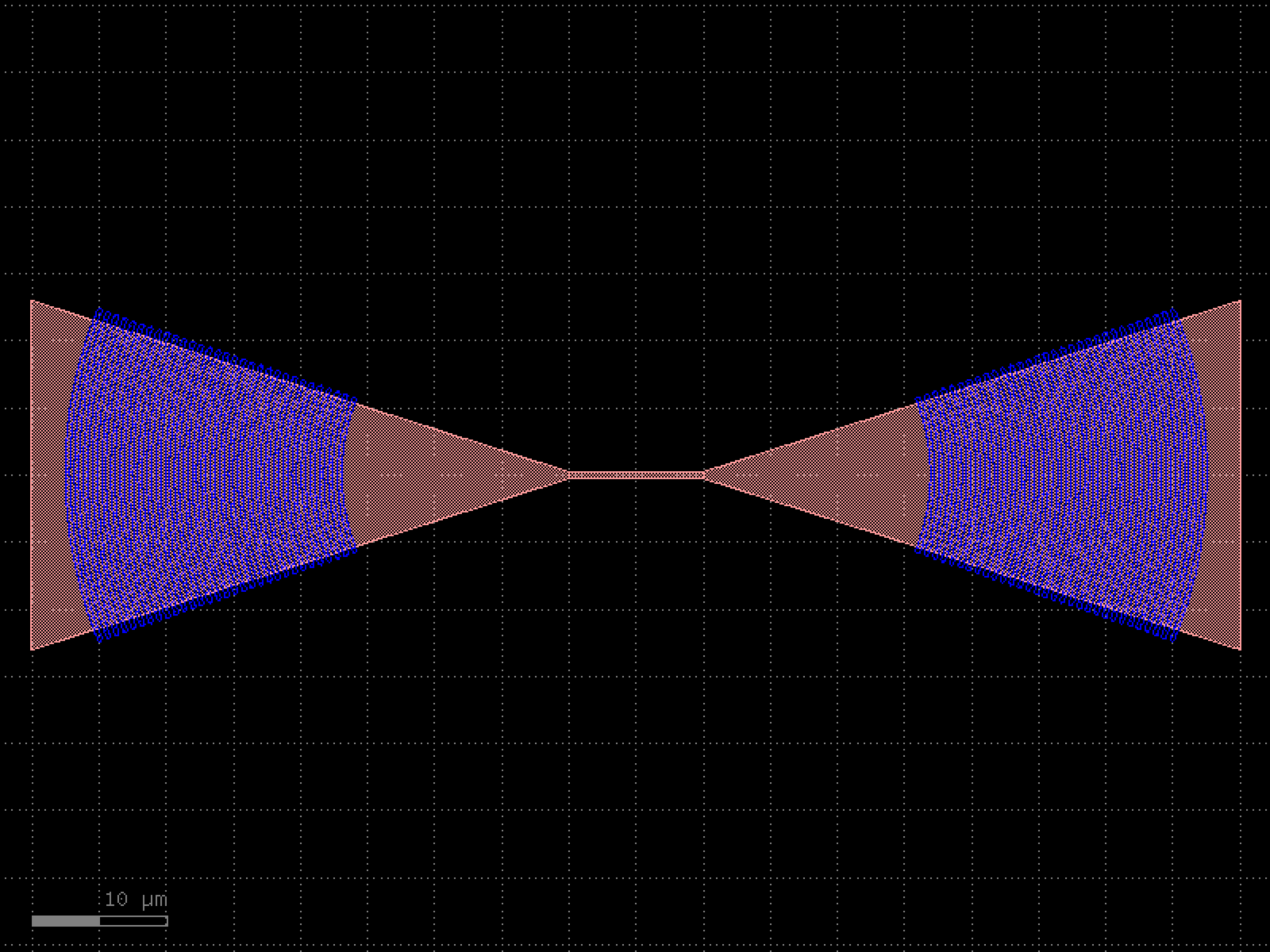
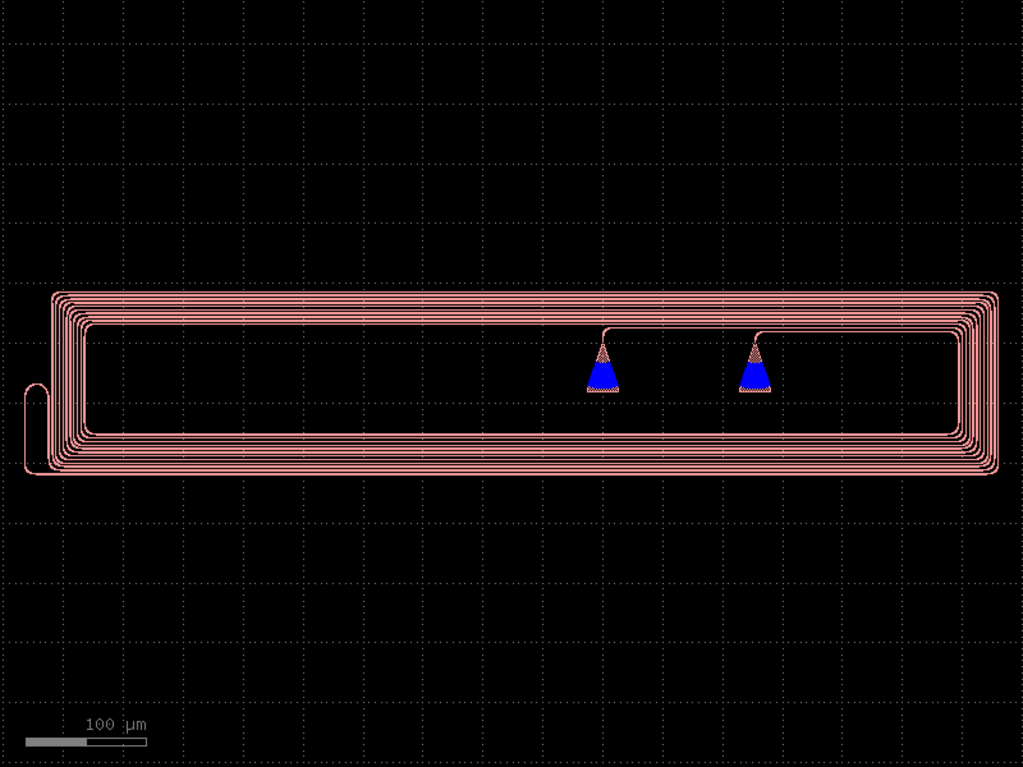
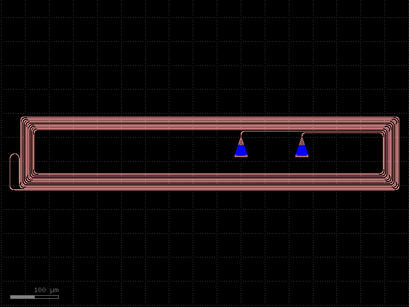
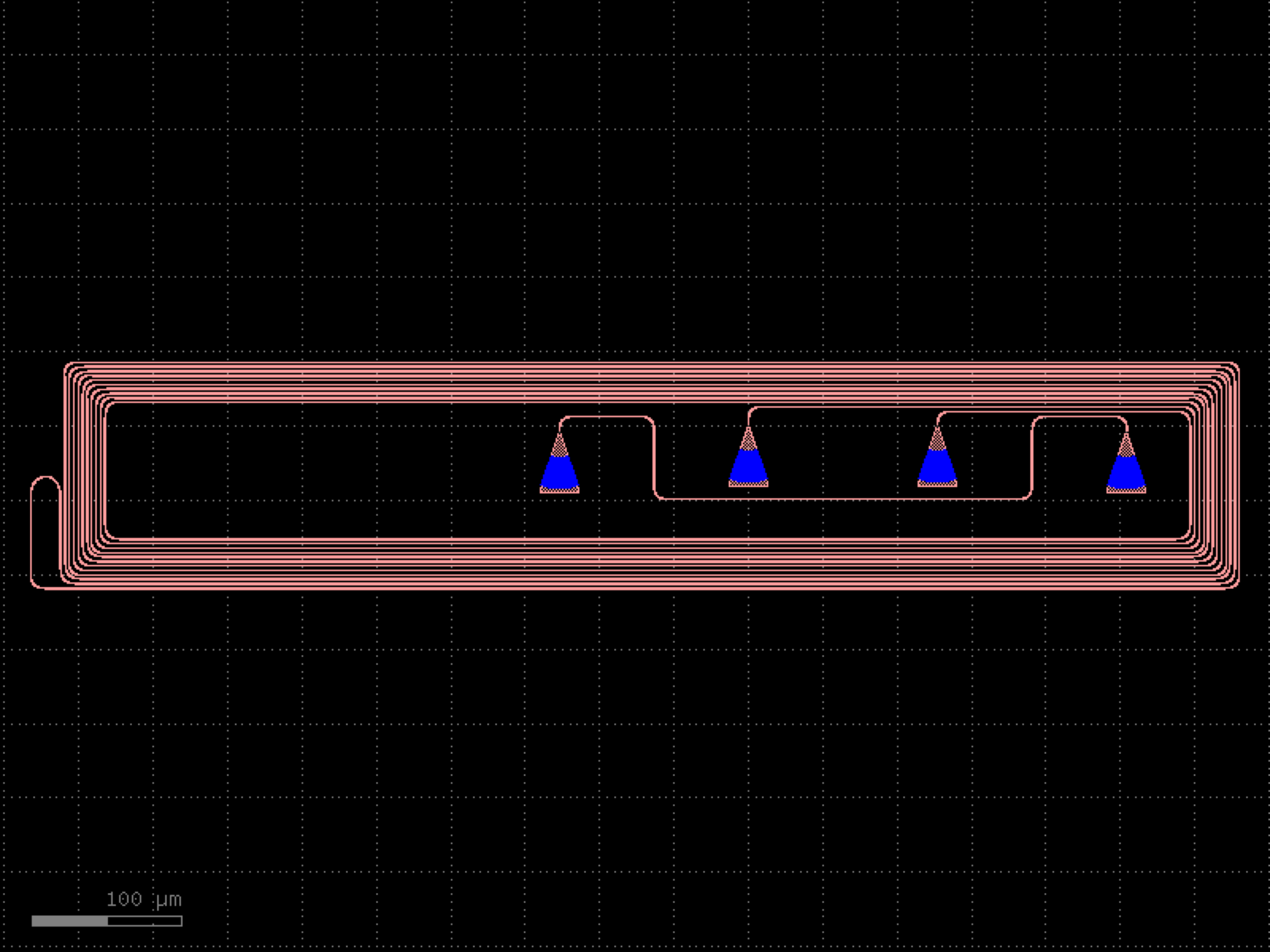
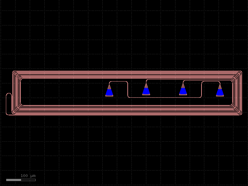
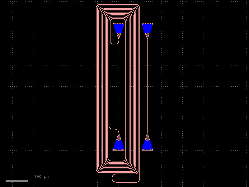
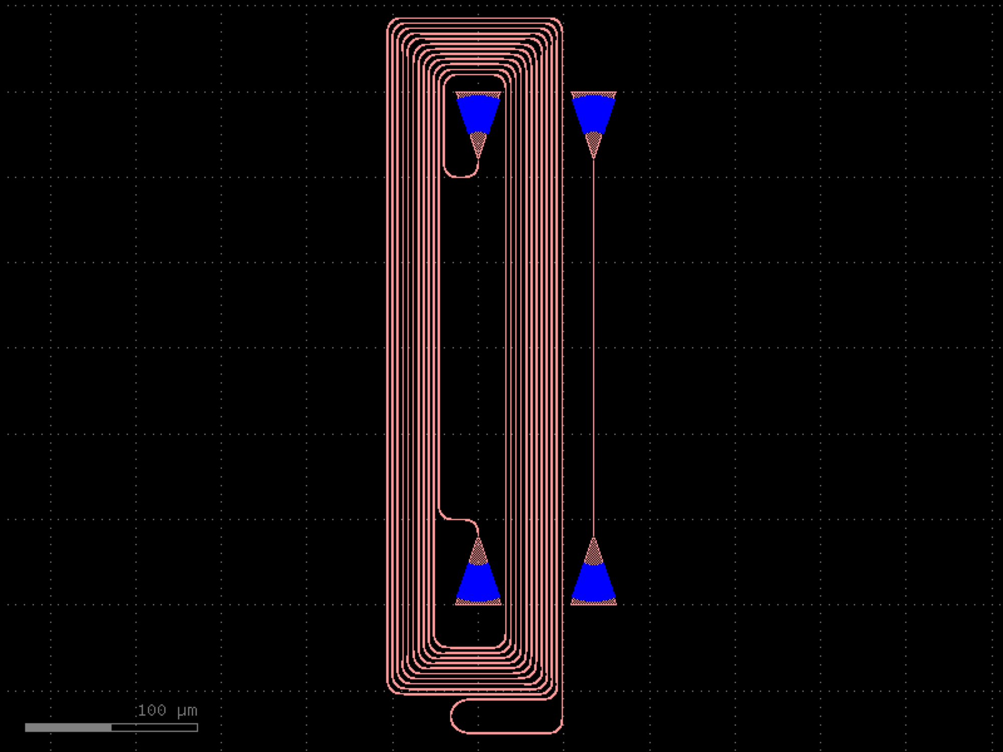
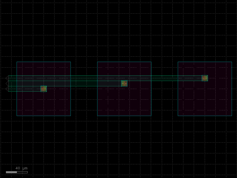
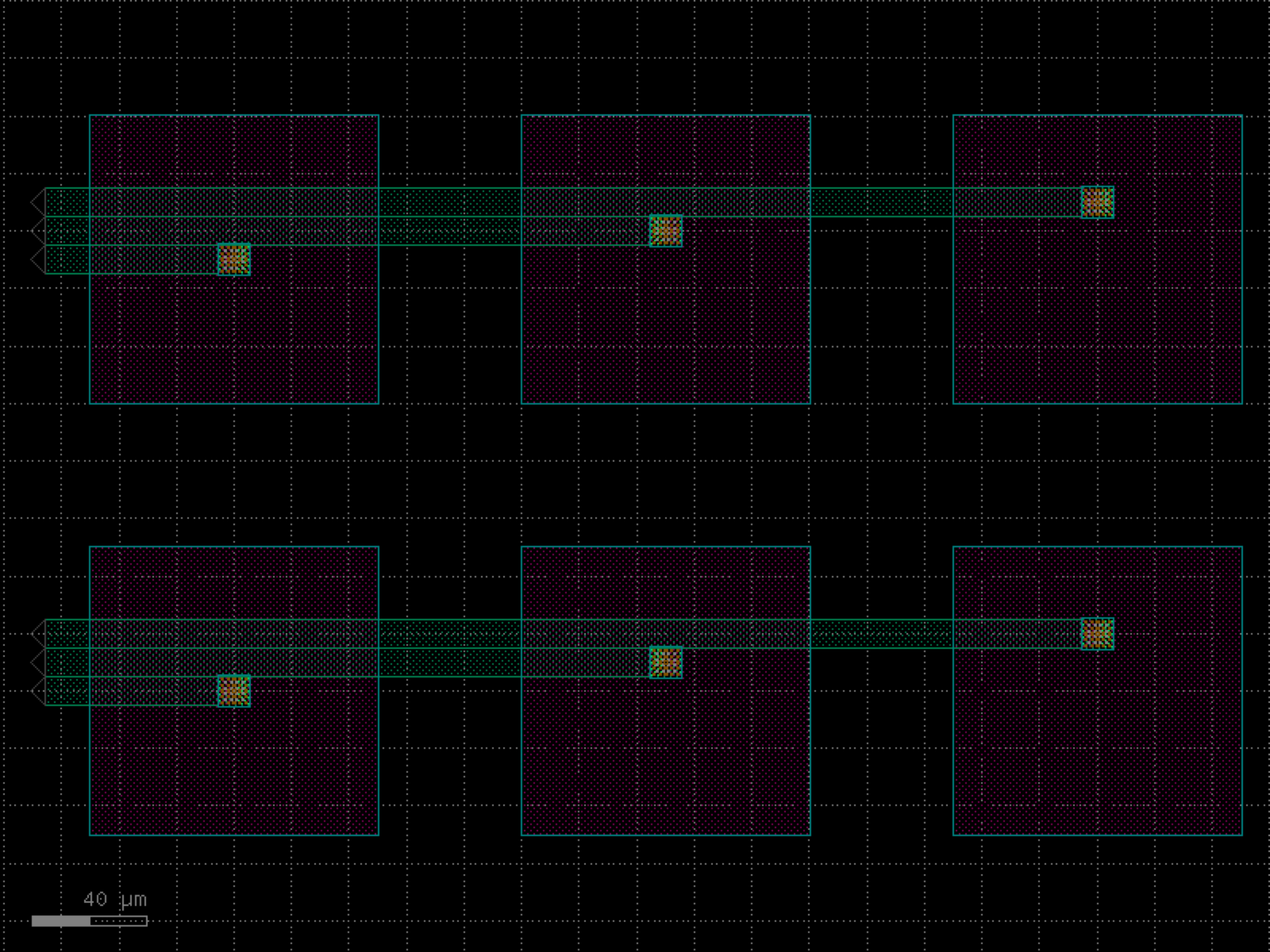
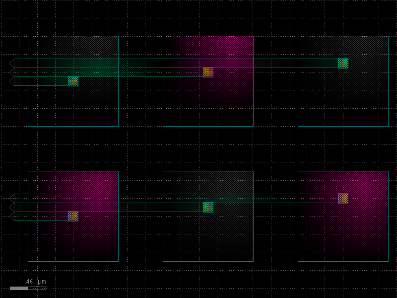
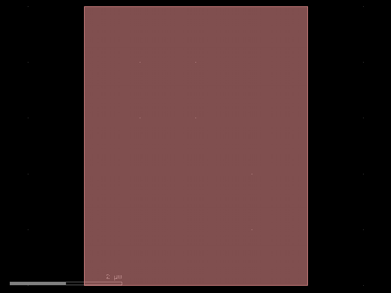
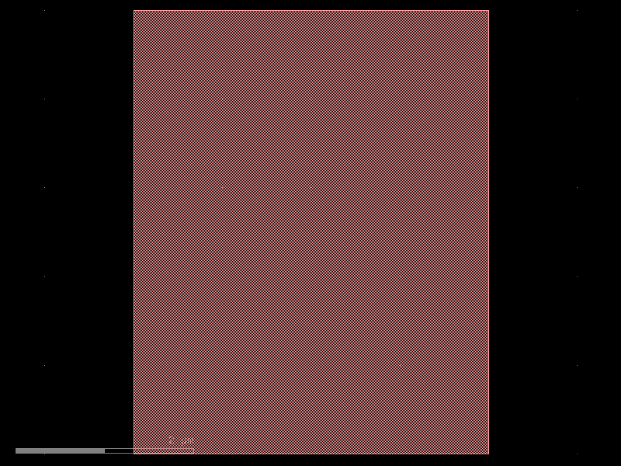
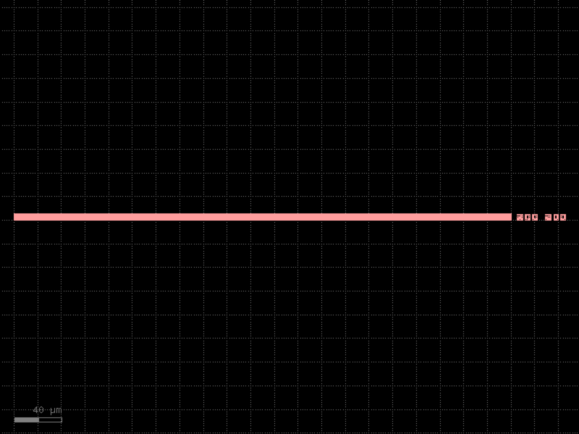
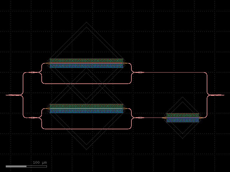
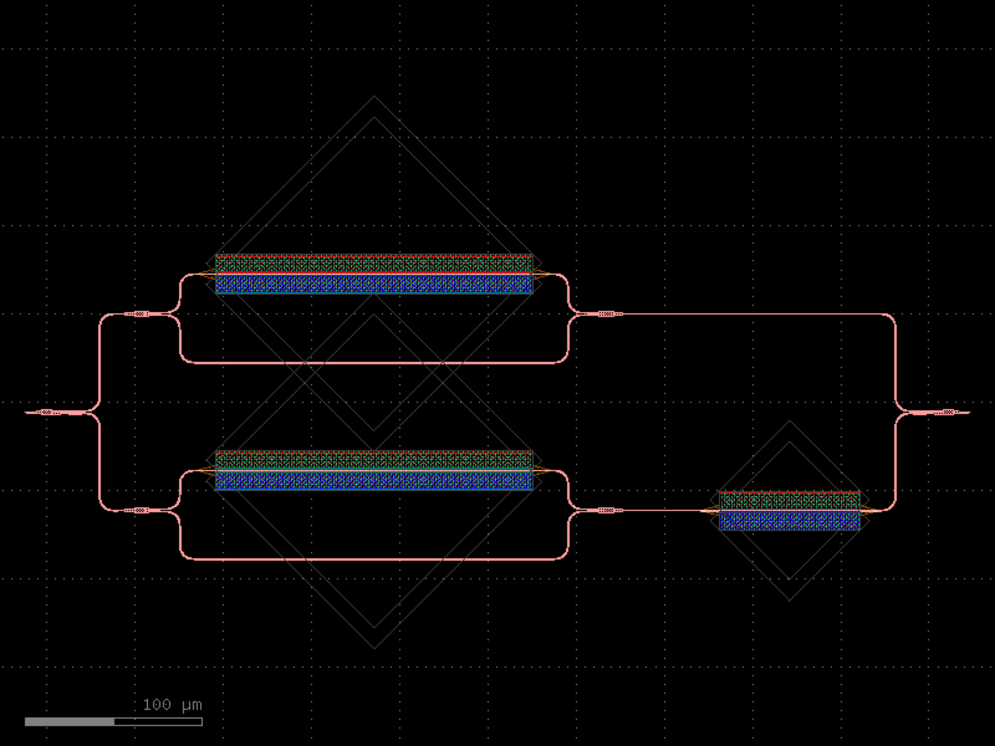
- gdsfactory.components.analog.inductor(width=2.0, space=2.1, diameter=25.35, resistance=0.5777, inductance=3.3303e-11, turns=1, layer_metal='M3', layer_inductor='M1', layer_metal_pin='WG_PIN', layers_no_fill=('DEVREC', 'NO_TILE_SI'))[source]#
Create a 2-turn inductor.
- Parameters:
width (float) – Width of the inductor trace in micrometers.
space (float) – Space between turns in micrometers.
diameter (float) – Inner diameter in micrometers.
resistance (float) – Resistance in ohms.
inductance (float) – Inductance in henries.
turns (int) – Number of turns (default 1 for inductor2).
layer_metal (tuple[int, int] | str | int | LayerEnum) – Layer for the metal trace.
layer_inductor (tuple[int, int] | str | int | LayerEnum) – Layer for the inductor region.
layer_metal_pin (tuple[int, int] | str | int | LayerEnum) – Layer for the metal pins.
layers_no_fill (Sequence[tuple[int, int] | str | int | LayerEnum]) – Layers to exclude from fill.
- Returns:
Component with inductor layout.
- Return type:
import gdsfactory as gf

gf.gpdk.PDK.activate()

c = gf.components.inductor(width=2, space=2.1, diameter=25.35, resistance=0.578, inductance=0.0, turns=1, layer_metal='M3', layer_inductor='M1', layer_metal_pin='WG_PIN', layers_no_fill=('DEVREC', 'NO_TILE_SI')).copy()
c.draw_ports()
c.plot()
(Source code, png, hires.png, pdf)
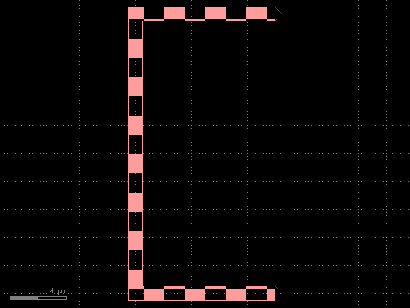
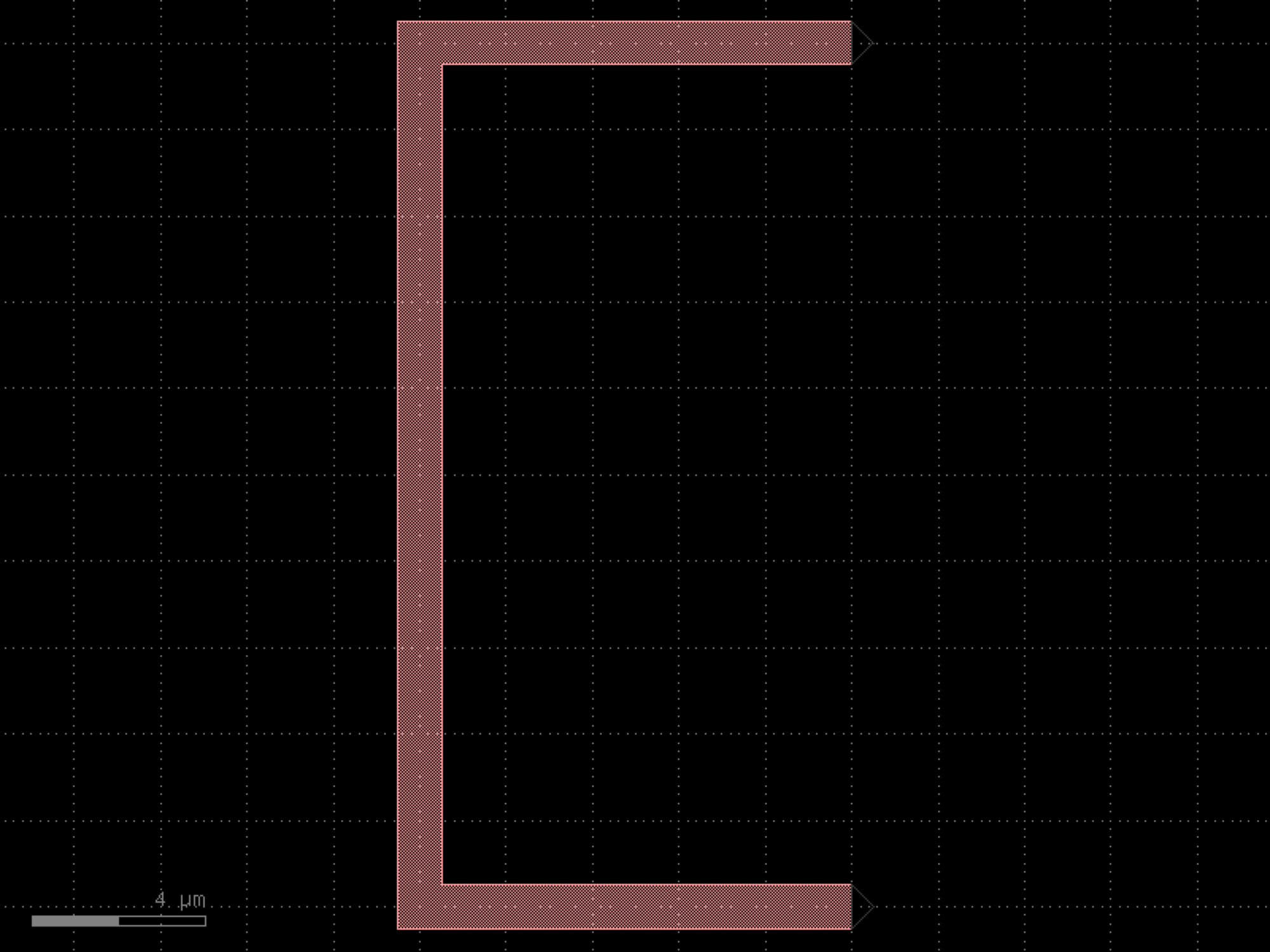
- gdsfactory.components.analog.interdigital_capacitor(fingers=4, finger_length=20.0, finger_gap=2.0, thickness=5.0, layer='WG')[source]#
Generate an interdigital capacitor component with ports on both ends.
An interdigital capacitor consists of interleaved metal fingers that create a distributed capacitance. This component creates a planar capacitor with two sets of interleaved fingers extending from opposite ends.
See for example Zhu et al., Accurate circuit model of interdigital capacitor and its application to design of new quasi-lumped miniaturized filters with suppression of harmonic resonance, doi: 10.1109/22.826833.
Note
finger_length=0effectively provides a parallel plate capacitor. The capacitance scales approximately linearly with the number of fingers and finger length.- Parameters:
fingers (int) – Total number of fingers of the capacitor (must be >= 1).
finger_length (float | int) – Length of each finger in μm.
finger_gap (float | int) – Gap between adjacent fingers in μm.
thickness (float | int) – Thickness of fingers and the base section in μm.
layer (LayerSpec) – Layer specification for the capacitor geometry.
- Returns:
A gdsfactory component with the interdigital capacitor geometry and two ports (‘o1’ and ‘o2’) on opposing sides.
- Return type:
import gdsfactory as gf

gf.gpdk.PDK.activate()

c = gf.components.interdigital_capacitor(fingers=4, finger_length=20, finger_gap=2, thickness=5, layer='WG').copy()
c.draw_ports()
c.plot()
(Source code, png, hires.png, pdf)

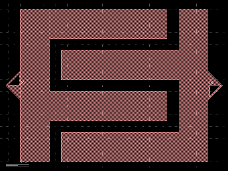
- gdsfactory.components.analog.interdigitated_electrodes(n_fingers=10, finger_width=0.5, finger_length=10.0, finger_gap=0.5, bus_width=2.0, bus_length=None, layer='MTOP', port_type='electrical')[source]#
Interdigitated electrode pattern.
Two horizontal bus bars (top and bottom) with alternating fingers extending from each bus toward the opposite one. Fingers from the top bus extend downward and fingers from the bottom bus extend upward, interleaving with a gap between the finger tips and the opposite bus.
- Parameters:
n_fingers (int) – Total number of fingers (split between top and bottom buses).
finger_width (float) – Width of each finger in um.
finger_length (float) – Length of each finger in um.
finger_gap (float) – Gap between adjacent fingers (edge to edge) in um.
bus_width (float) – Width (height) of each bus bar in um.
bus_length (float | None) – Length of each bus bar in um. Defaults to the total width needed to accommodate all fingers.
layer (LayerSpec) – Layer specification for all geometry.
port_type (str) – Port type for electrical ports at bus bar ends.
- Return type:
import gdsfactory as gf

gf.gpdk.PDK.activate()

c = gf.components.interdigitated_electrodes(n_fingers=10, finger_width=0.5, finger_length=10, finger_gap=0.5, bus_width=2, layer='MTOP', port_type='electrical').copy()
c.draw_ports()
c.plot()
(Source code, png, hires.png, pdf)
bends#
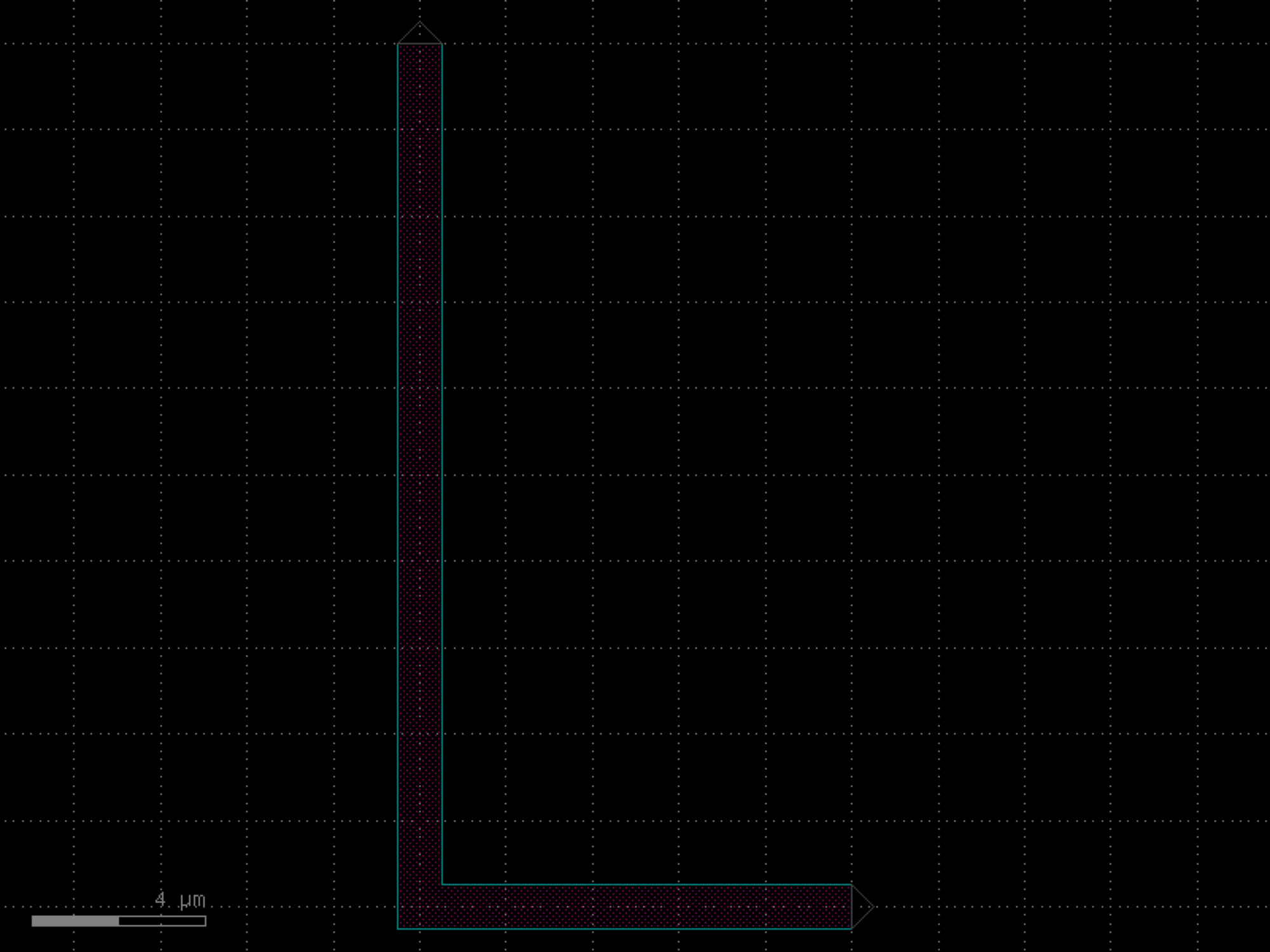
- gdsfactory.components.bends.bend_circular(radius=None, angle=90.0, npoints=None, angular_step=None, layer=None, width=None, cross_section='strip', allow_min_radius_violation=False)[source]#
Returns a radial arc.
- Parameters:
radius (float | None) – in um. Defaults to cross_section_radius.
angle (float) – angle of arc (degrees).
npoints (int | None) – number of points.
angular_step (float | None) – If provided, determines the angular step (in degrees) between points. Mutually exclusive with npoints.
layer (tuple[int, int] | str | int | LayerEnum | None) – layer to use. Defaults to cross_section.layer.
width (float | None) – width to use. Defaults to cross_section.width.
cross_section (CrossSectionSpec) – spec (CrossSection, string or dict).
allow_min_radius_violation (bool) – if True allows radius to be smaller than cross_section radius.
- Return type:
import gdsfactory as gf

gf.gpdk.PDK.activate()

c = gf.components.bend_circular(angle=90, cross_section='strip', allow_min_radius_violation=False).copy()
c.draw_ports()
c.plot()
(Source code, png, hires.png, pdf)
- gdsfactory.components.bends.bend_circular_all_angle(radius=None, angle=90.0, npoints=None, angular_step=None, layer=None, width=None, cross_section='strip', allow_min_radius_violation=False)[source]#
Returns a radial arc.
- Parameters:
radius (float | None) – in um. Defaults to cross_section_radius.
angle (float) – angle of arc (degrees).
npoints (int | None) – number of points.
angular_step (float | None) – If provided, determines the angular step (in degrees) between points. Mutually exclusive with npoints.
layer (tuple[int, int] | str | int | LayerEnum | None) – layer to use. Defaults to cross_section.layer.
width (float | None) – width to use. Defaults to cross_section.width.
cross_section (CrossSectionSpec) – spec (CrossSection, string or dict).
allow_min_radius_violation (bool) – if True allows radius to be smaller than cross_section radius.
- Return type:
import gdsfactory as gf

gf.gpdk.PDK.activate()

c = gf.components.bend_circular_all_angle(angle=90, cross_section='strip', allow_min_radius_violation=False).copy()
c.draw_ports()
c.plot()
(Source code, png, hires.png, pdf)
- gdsfactory.components.bends.bend_circular_heater(radius=None, angle=90, npoints=None, heater_to_wg_distance=1.2, heater_width=0.5, layer_heater='HEATER', cross_section='strip', allow_min_radius_violation=False)[source]#
Creates an arc of arclength theta starting at angle start_angle.
- Parameters:
radius (float | None) – in um. Defaults to cross_section.radius.
angle (float) – angle of arc (degrees).
npoints (int | None) – Number of points used per 360 degrees.
heater_to_wg_distance (float) – in um.
heater_width (float) – in um.
layer_heater (LayerSpec) – for heater.
cross_section (CrossSectionSpec) – specification (CrossSection, string, CrossSectionFactory dict).
allow_min_radius_violation (bool) – if True allows radius to be smaller than cross_section radius.
- Return type:
import gdsfactory as gf

gf.gpdk.PDK.activate()

c = gf.components.bend_circular_heater(angle=90, heater_to_wg_distance=1.2, heater_width=0.5, layer_heater='HEATER', cross_section='strip', allow_min_radius_violation=False).copy()
c.draw_ports()
c.plot()
(Source code, png, hires.png, pdf)
- gdsfactory.components.bends.bend_euler(radius=None, angle=90.0, p=0.5, with_arc_floorplan=True, npoints=None, angular_step=None, layer=None, width=None, cross_section='strip', allow_min_radius_violation=False)[source]#
Regular degree euler bend.
- Parameters:
radius (float | None) – in um. Defaults to cross_section_radius.
angle (float) – total angle of the curve.
p (float) – Proportion of the curve that is an Euler curve.
with_arc_floorplan (bool) – if True the size of the bend will be adjusted to match an arc bend with the specified radius. If False: radius is the minimum radius of curvature.
npoints (int | None) – Number of points used per 360 degrees.
angular_step (float | None) – if not None, the angle step in degrees for the all_angle bend.
layer (LayerSpec | None) – layer to use. Defaults to cross_section.layer.
width (float | None) – width to use. Defaults to cross_section.width.
cross_section (CrossSectionSpec) – specification (CrossSection, string, CrossSectionFactory dict).
allow_min_radius_violation (bool) – if True allows radius to be smaller than cross_section radius.
- Return type:
import gdsfactory as gf

gf.gpdk.PDK.activate()

c = gf.components.bend_euler(angle=90, p=0.5, with_arc_floorplan=True, cross_section='strip', allow_min_radius_violation=False).copy()
c.draw_ports()
c.plot()
(Source code, png, hires.png, pdf)

- gdsfactory.components.bends.bend_euler_all_angle(radius=None, angle=90.0, p=0.5, with_arc_floorplan=True, npoints=None, angular_step=None, layer=None, width=None, cross_section='strip', allow_min_radius_violation=False)[source]#
Regular degree euler bend.
- Parameters:
radius (float | None) – in um. Defaults to cross_section_radius.
angle (float) – total angle of the curve.
p (float) – Proportion of the curve that is an Euler curve.
with_arc_floorplan (bool) – If False: radius is the minimum radius of curvature
npoints (int | None) – Number of points used per 360 degrees.
angular_step (float | None) – if not None, the angle step in degrees for the all_angle bend.
layer (tuple[int, int] | str | int | LayerEnum | None) – layer to use. Defaults to cross_section.layer.
width (float | None) – width to use. Defaults to cross_section.width.
cross_section (CrossSectionSpec) – specification (CrossSection, string, CrossSectionFactory dict).
allow_min_radius_violation (bool) – if True allows radius to be smaller than cross_section radius.
- Return type:
import gdsfactory as gf

gf.gpdk.PDK.activate()

c = gf.components.bend_euler_all_angle(angle=90, p=0.5, with_arc_floorplan=True, cross_section='strip', allow_min_radius_violation=False).copy()
c.draw_ports()
c.plot()
(Source code, png, hires.png, pdf)
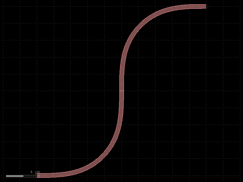
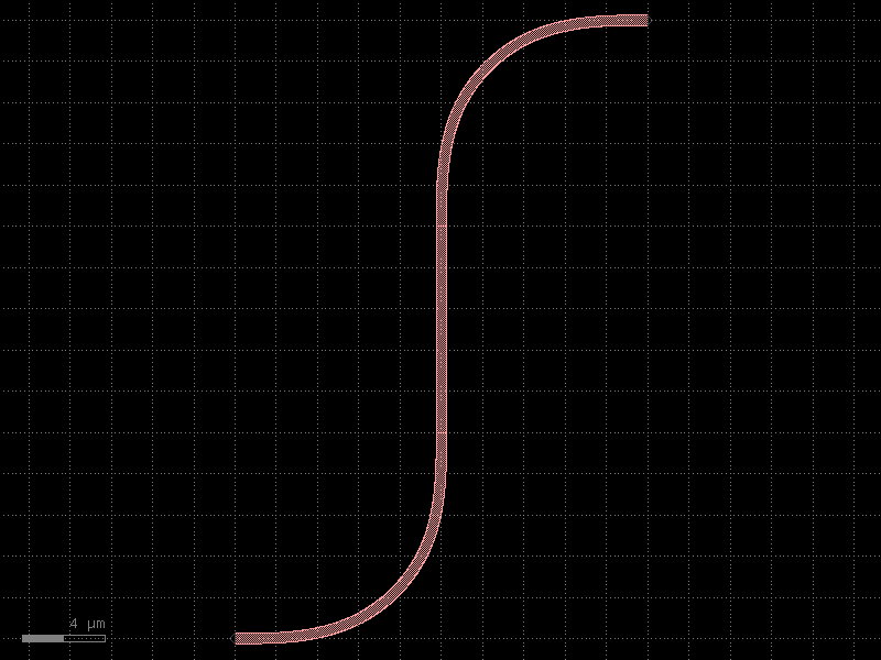
- gdsfactory.components.bends.bend_euler_s(radius=None, p=0.5, with_arc_floorplan=True, npoints=None, angular_step=None, layer=None, width=None, cross_section='strip', allow_min_radius_violation=False, port1='o1', port2='o2')[source]#
Sbend made of 2 euler bends.
- Parameters:
radius (float | None) – in um. Defaults to cross_section_radius.
p (float) – Proportion of the curve that is an Euler curve.
with_arc_floorplan (bool) – If False: radius is the minimum radius of curvature.
npoints (int | None) – Number of points used per 360 degrees.
angular_step (float | None) – if not None, the angle step in degrees for the all_angle bend.
layer (LayerSpec | None) – layer to use. Defaults to cross_section.layer.
width (float | None) – width to use. Defaults to cross_section.width.
cross_section (CrossSectionSpec) – specification (CrossSection, string, CrossSectionFactory dict).
allow_min_radius_violation (bool) – if True allows radius to be smaller than cross_section radius.
port1 (str) – input port name.
port2 (str) – output port name.
- Return type:
               _____ o2
              /
             /
            /
           /
           |
          /
         /
        /
o1_____/
import gdsfactory as gf

gf.gpdk.PDK.activate()

c = gf.components.bend_euler_s(p=0.5, with_arc_floorplan=True, cross_section='strip', allow_min_radius_violation=False, port1='o1', port2='o2').copy()
c.draw_ports()
c.plot()
(Source code, png, hires.png, pdf)
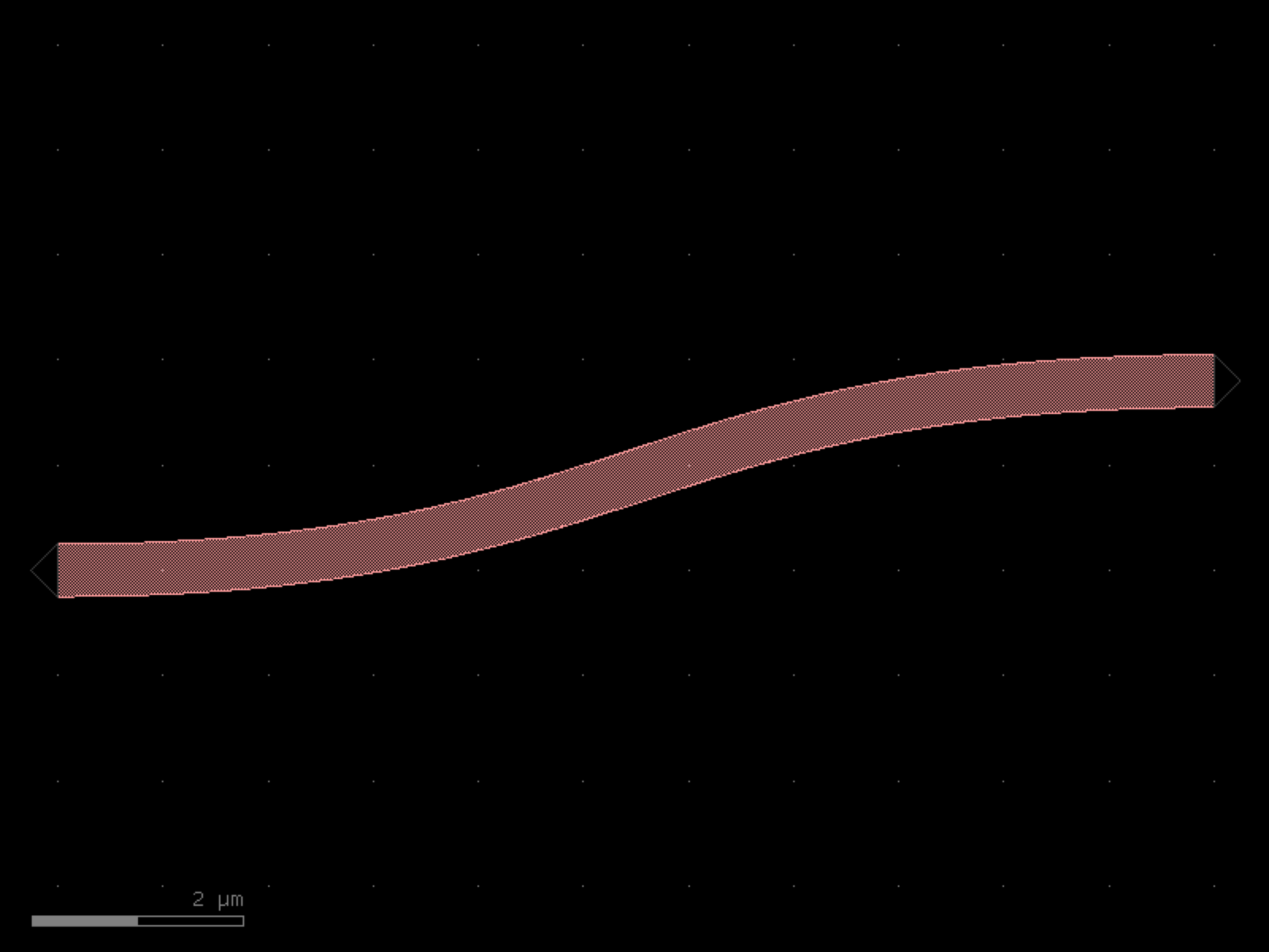
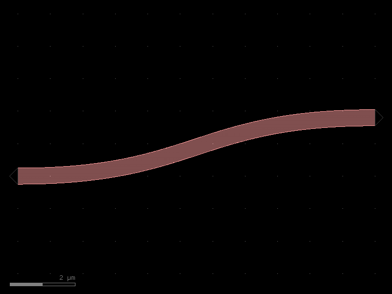
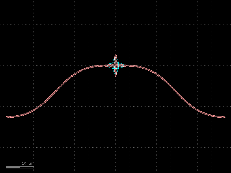
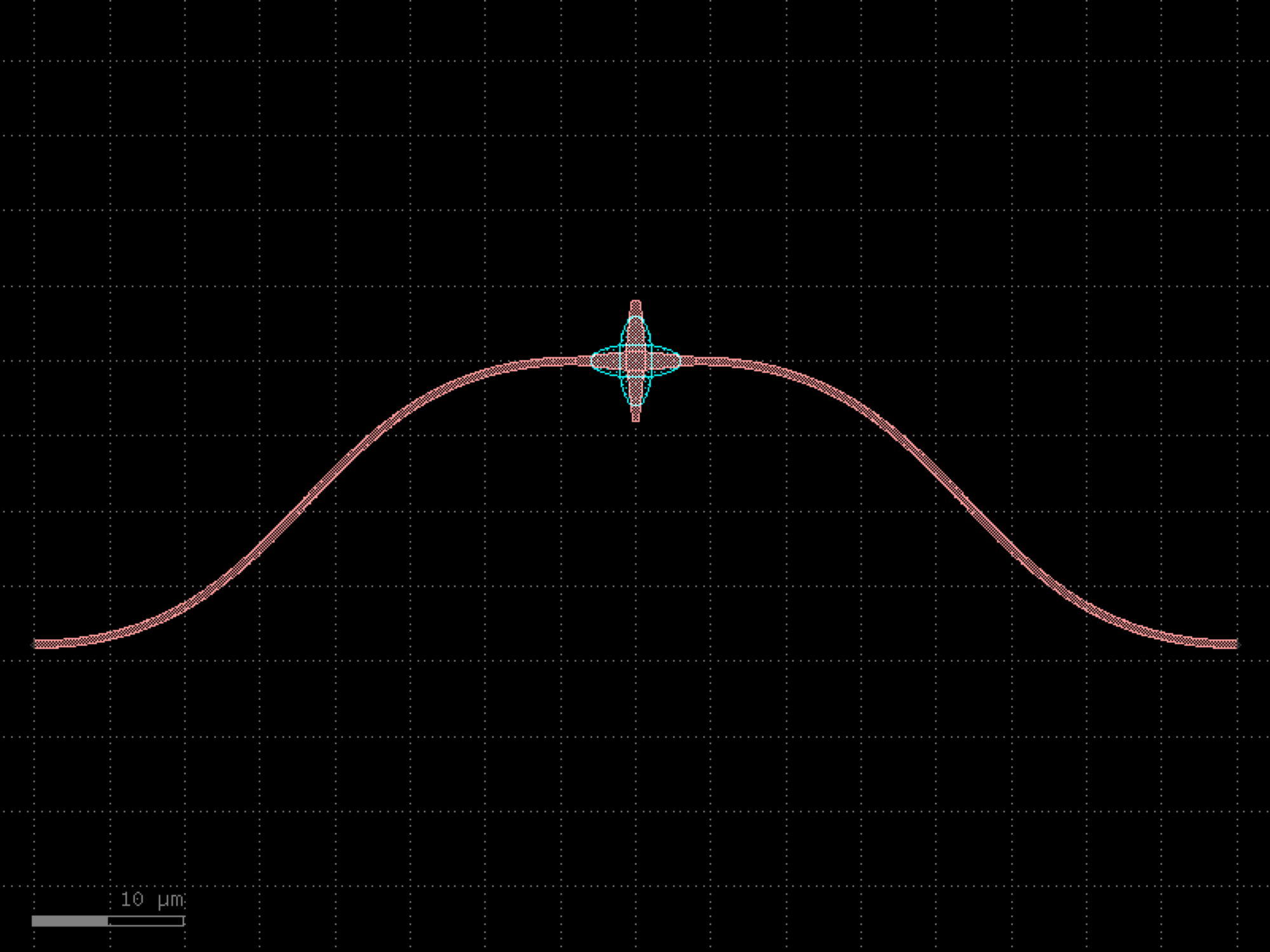
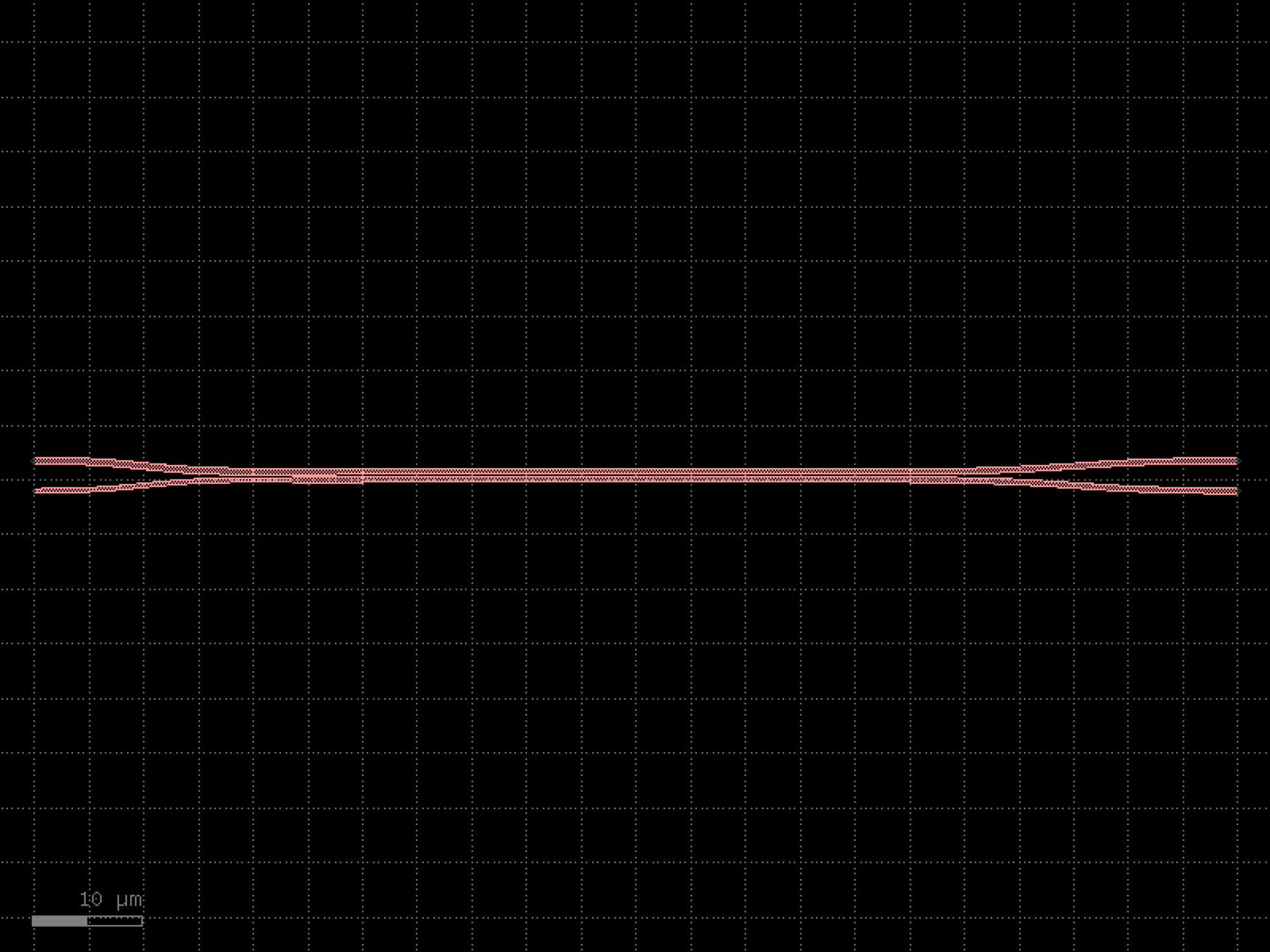
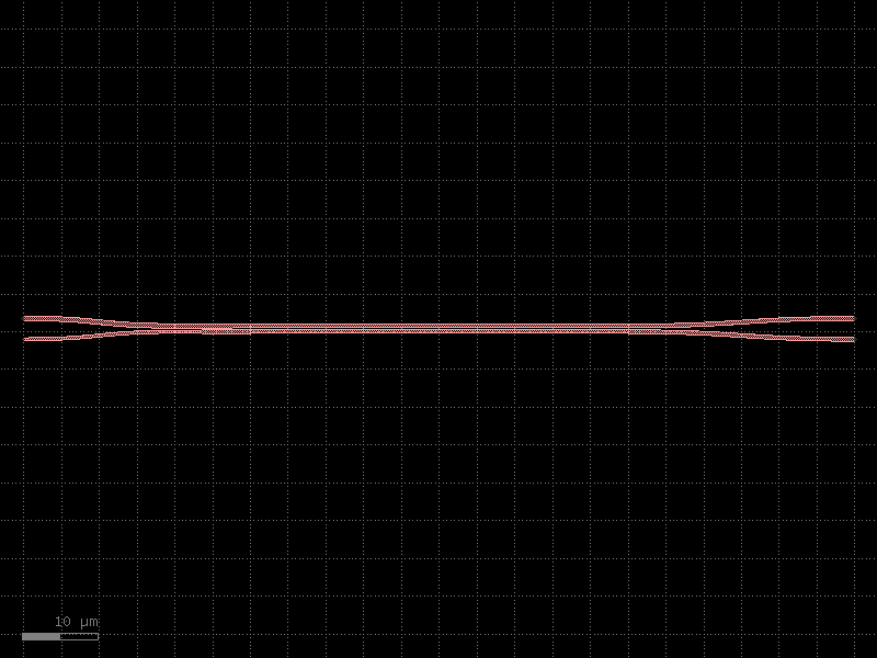
- gdsfactory.components.bends.bend_s(size=(11.0, 1.8), npoints=99, cross_section='strip', allow_min_radius_violation=False, width=None)[source]#
Return S bend with bezier curve.
stores min_bend_radius property in self.info[‘min_bend_radius’] min_bend_radius depends on height and length
- Parameters:
size (tuple[float, float]) – in x and y direction.
npoints (int) – number of points.
cross_section (CrossSectionSpec) – spec.
allow_min_radius_violation (bool) – bool.
width (float | None) – width to use. Defaults to cross_section.width.
- Return type:
import gdsfactory as gf

gf.gpdk.PDK.activate()

c = gf.components.bend_s(size=(11, 1.8), npoints=99, cross_section='strip', allow_min_radius_violation=False).copy()
c.draw_ports()
c.plot()
(Source code, png, hires.png, pdf)

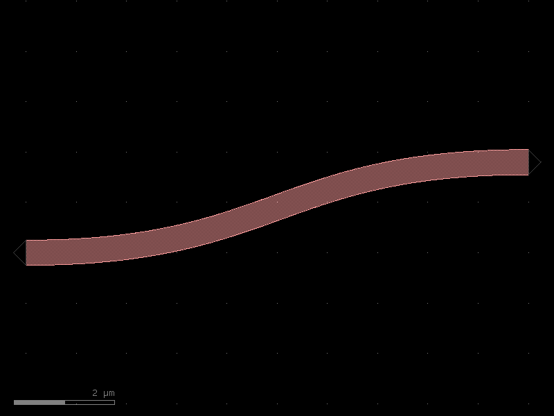
- gdsfactory.components.bends.bend_s_offset(offset=40.0, radius=10.0, cross_section='strip', width=None, with_euler=None, p=1, with_arc_floorplan=False, npoints=None, angular_step=None)[source]#
Return S bend made of two bends with a straight section.
- Parameters:
offset (float) – in um.
radius (float | None) – in um. if None, uses cross_section_radius.
cross_section (CrossSectionSpec) – spec.
width (float | None) – width to use. Defaults to cross_section.width.
with_euler (bool | None) – deprecated, use p=0 for circular arc instead.
p (float) – 1 means standard Euler bend. 0 means circular arc.
with_arc_floorplan (bool) – if True the size of the bend will be adjusted to match an arc bend with the specified radius. If False: radius is the minimum radius of curvature.
npoints (int | None) – number of points.
angular_step (float | None) – If provided, determines the angular step (in degrees) between points. Mutually exclusive with npoints.
- Return type:
import gdsfactory as gf

gf.gpdk.PDK.activate()

c = gf.components.bend_s_offset(offset=40, radius=10, cross_section='strip', p=1, with_arc_floorplan=False).copy()
c.draw_ports()
c.plot()
(Source code, png, hires.png, pdf)
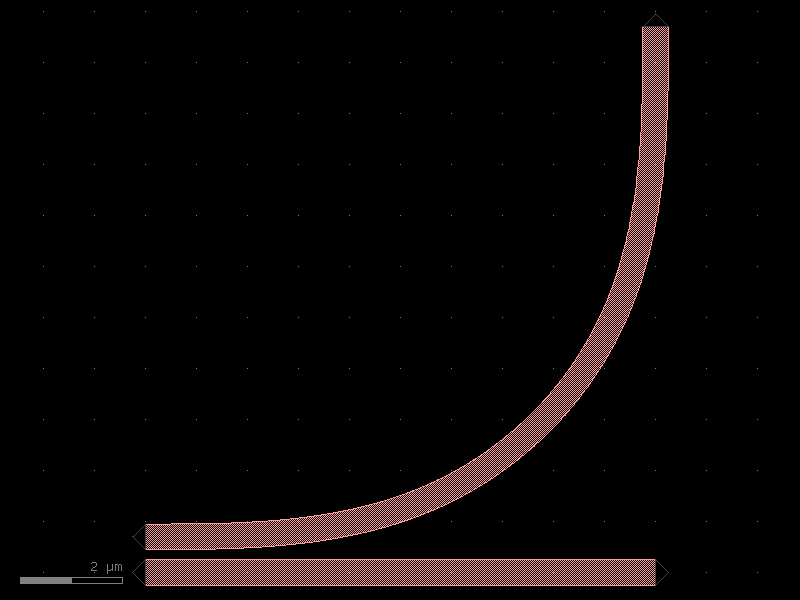
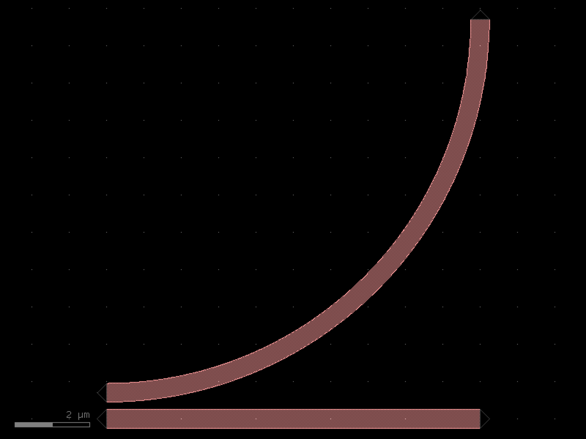
- gdsfactory.components.bends.bend_topic(radius=None, angle=90.0, p=0.1, npoints=100, cross_section='strip', allow_min_radius_violation=False, layer=None, width=None)[source]#
Returns a regular degree Third Order Polynomial Interconnected Circular (TOPIC) bend component.
The implementation follows the description in this publication https://arxiv.org/html/2411.15025v1.
The bend consists of three parts: a. Initial transition from straight to bend, known as TOP segment. b. Circular part whose center and radius are calculated analytically. c. Mirroring of TOP segment with respect to the bisection of the angle.
- Parameters:
radius (float | None) – radius at the start and end of bend.
angle (float) – total angle of the curve in degrees.
p (float) – used to calculate the angle of the bend at the end of TOP / start of circular arc, as p*angle. It should be within [0, 0.5).
npoints (int) – Number of points used per 360 degrees.
cross_section (CrossSectionSpec) – specification (CrossSection, string, CrossSectionFactory dict).
allow_min_radius_violation (bool) – if True allows radius to be smaller than cross_section radius.
layer (LayerSpec | None) – layer to use. Defaults to cross_section.layer.
width (float | None) – width to use. Defaults to cross_section.width.
- Return type:
import gdsfactory as gf

gf.gpdk.PDK.activate()

c = gf.components.bend_topic(angle=90, p=0.1, npoints=100, cross_section='strip', allow_min_radius_violation=False).copy()
c.draw_ports()
c.plot()
(Source code, png, hires.png, pdf)
- gdsfactory.components.bends.bend_topic180(radius=None, *, angle=180, p=0.1, npoints=100, cross_section='strip', allow_min_radius_violation=False, layer=None, width=None)#
Returns a regular degree Third Order Polynomial Interconnected Circular (TOPIC) bend component.
The implementation follows the description in this publication https://arxiv.org/html/2411.15025v1.
The bend consists of three parts: a. Initial transition from straight to bend, known as TOP segment. b. Circular part whose center and radius are calculated analytically. c. Mirroring of TOP segment with respect to the bisection of the angle.
- Parameters:
radius (float | None) – radius at the start and end of bend.
angle (float) – total angle of the curve in degrees.
p (float) – used to calculate the angle of the bend at the end of TOP / start of circular arc, as p*angle. It should be within [0, 0.5).
npoints (int) – Number of points used per 360 degrees.
cross_section (CrossSectionSpec) – specification (CrossSection, string, CrossSectionFactory dict).
allow_min_radius_violation (bool) – if True allows radius to be smaller than cross_section radius.
layer (LayerSpec | None) – layer to use. Defaults to cross_section.layer.
width (float | None) – width to use. Defaults to cross_section.width.
- Return type:
import gdsfactory as gf

gf.gpdk.PDK.activate()

c = gf.components.bend_topic180(angle=180, p=0.1, npoints=100, cross_section='strip', allow_min_radius_violation=False).copy()
c.draw_ports()
c.plot()
(Source code, png, hires.png, pdf)

- gdsfactory.components.bends.bend_topic_all_angle(radius=None, angle=90.0, p=0.1, npoints=100, cross_section='strip', allow_min_radius_violation=False, layer=None, width=None)[source]#
Returns a Third Order Polynomial Interconnected Circular (TOPIC) bend component of arbitrary angle.
The implementation follows the description in this publication https://arxiv.org/html/2411.15025v1.
The bend consists of three parts: a. Initial transition from straight to bend, known as TOP segment. b. Circular part whose center and radius are calculated analytically. c. Mirroring of TOP segment with respect to the bisection of the angle.
- Parameters:
radius (float | None) – radius at the start and end of bend.
angle (float) – total angle of the curve in degrees.
p (float) – used to calculate the angle of the bend at the end of TOP / start of circular arc, as p*angle. It should be within [0, 0.5).
npoints (int) – Number of points used per 360 degrees.
cross_section (CrossSectionSpec) – specification (CrossSection, string, CrossSectionFactory dict).
allow_min_radius_violation (bool) – if True allows radius to be smaller than cross_section radius.
layer (LayerSpec | None) – layer to use. Defaults to cross_section.layer.
width (float | None) – width to use. Defaults to cross_section.width.
- Return type:
import gdsfactory as gf

gf.gpdk.PDK.activate()

c = gf.components.bend_topic_all_angle(angle=90, p=0.1, npoints=100, cross_section='strip', allow_min_radius_violation=False).copy()
c.draw_ports()
c.plot()
(Source code, png, hires.png, pdf)
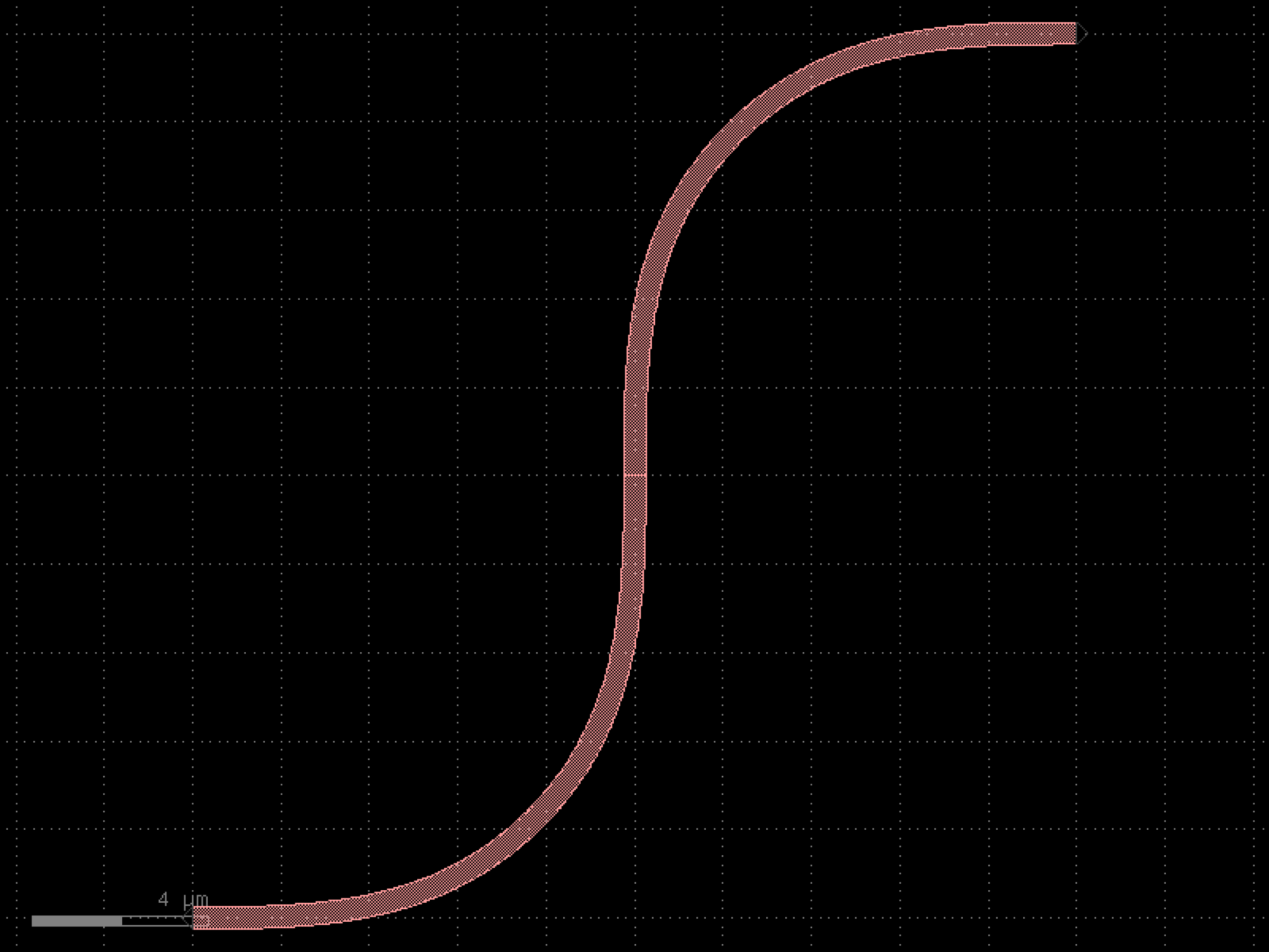
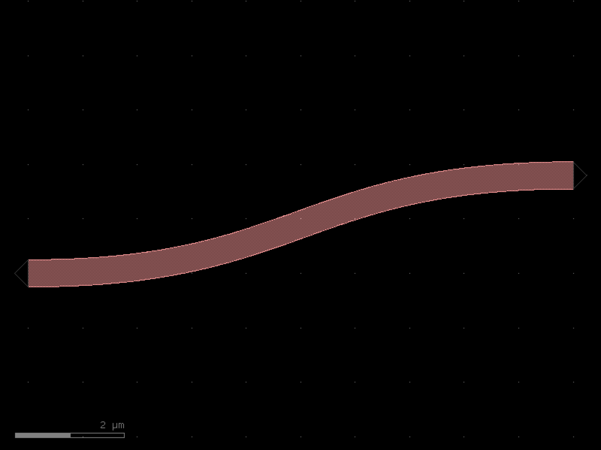
- gdsfactory.components.bends.bend_topic_s(radius=None, p=0.1, npoints=100, layer=None, width=None, cross_section='strip', allow_min_radius_violation=False, port1='o1', port2='o2')[source]#
Sbend made of 2 topic bends.
- Parameters:
radius (float | None) – radius at the start and end of bend.
p (float) – used to calculate the angle of the bend at the end of TOP / start of circular arc, as p*angle. It should be within [0, 0.5).
npoints (int) – Number of points used per 360 degrees.
cross_section (CrossSectionSpec) – specification (CrossSection, string, CrossSectionFactory dict).
allow_min_radius_violation (bool) – if True allows radius to be smaller than cross_section radius.
layer (LayerSpec | None) – layer to use. Defaults to cross_section.layer.
width (float | None) – width to use. Defaults to cross_section.width.
port1 (str) – input port name.
port2 (str) – output port name.
- Return type:
               _____ o2
              /
             /
            /
           /
           |
          /
         /
        /
o1_____/
import gdsfactory as gf

gf.gpdk.PDK.activate()

c = gf.components.bend_topic_s(p=0.1, npoints=100, cross_section='strip', allow_min_radius_violation=False, port1='o1', port2='o2').copy()
c.draw_ports()
c.plot()
(Source code, png, hires.png, pdf)
- gdsfactory.components.bends.bezier(control_points=((0.0, 0.0), (5.0, 0.0), (5.0, 1.8), (10.0, 1.8)), npoints=201, with_manhattan_facing_angles=True, start_angle=None, end_angle=None, cross_section='strip', bend_radius_error_type=None, allow_min_radius_violation=False, width=None)[source]#
Returns Bezier bend.
- Parameters:
control_points (Sequence[tuple[float, float]]) – list of points.
npoints (int) – number of points varying between 0 and 1.
with_manhattan_facing_angles (bool) – bool.
start_angle (int | None) – optional start angle in deg.
end_angle (int | None) – optional end angle in deg.
cross_section (CrossSectionSpec) – spec.
bend_radius_error_type (ErrorType | None) – error type.
allow_min_radius_violation (bool) – bool.
width (float | None) – width to use. Defaults to cross_section.width.
- Return type:
import gdsfactory as gf

gf.gpdk.PDK.activate()

c = gf.components.bezier(control_points=((0, 0), (5, 0), (5, 1.8), (10, 1.8)), npoints=201, with_manhattan_facing_angles=True, cross_section='strip', allow_min_radius_violation=False).copy()
c.draw_ports()
c.plot()
(Source code, png, hires.png, pdf)

containers#
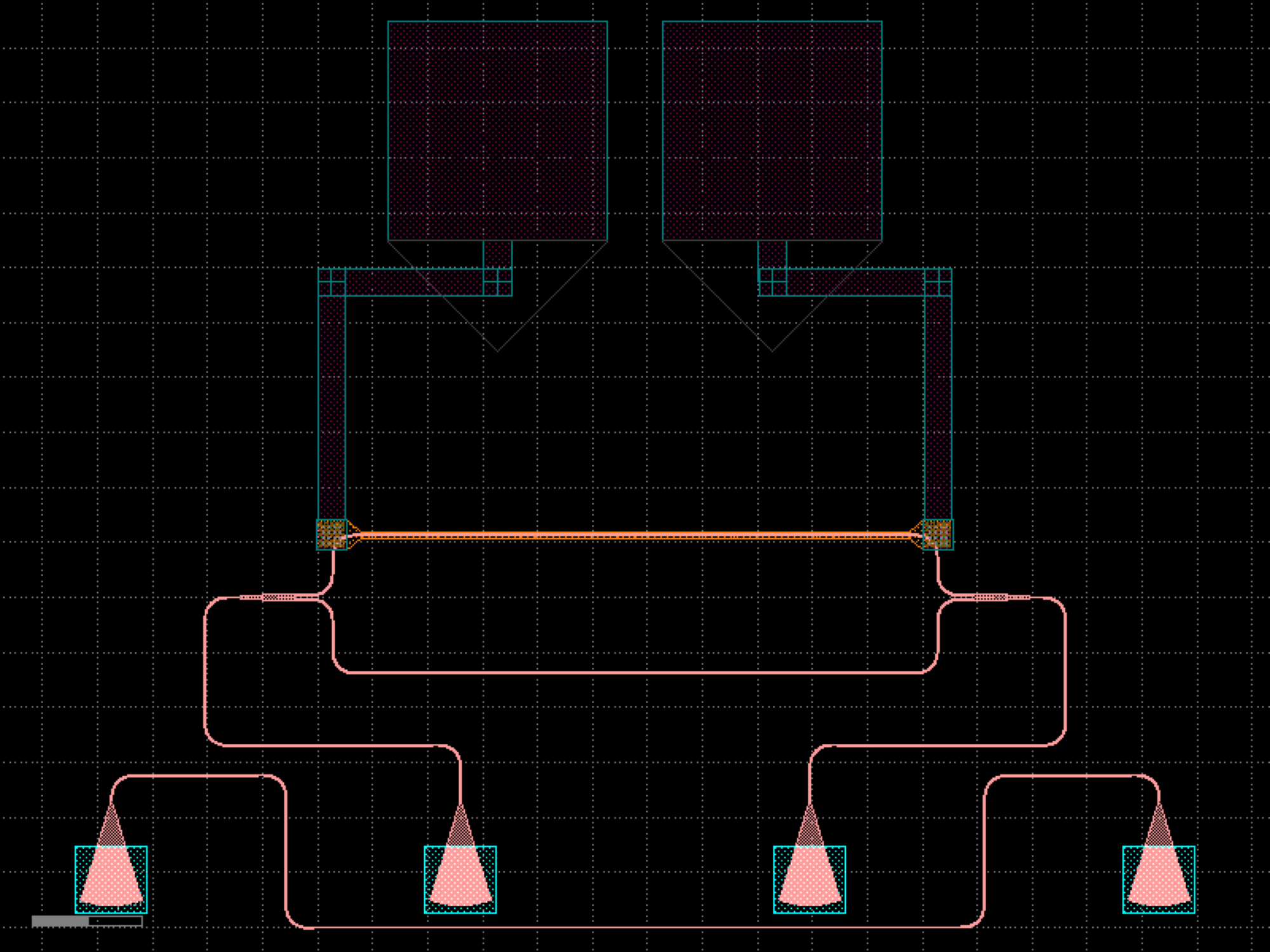
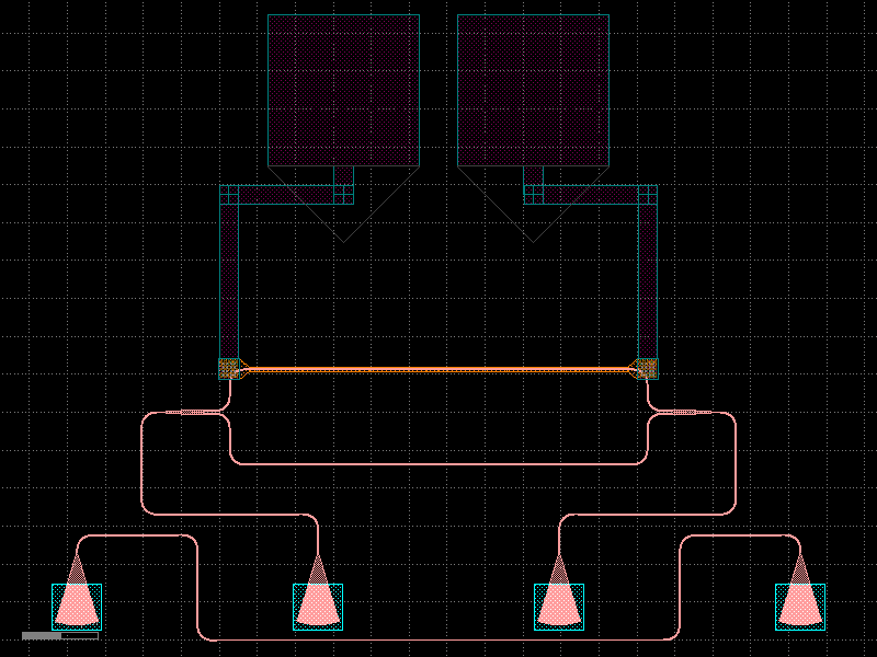
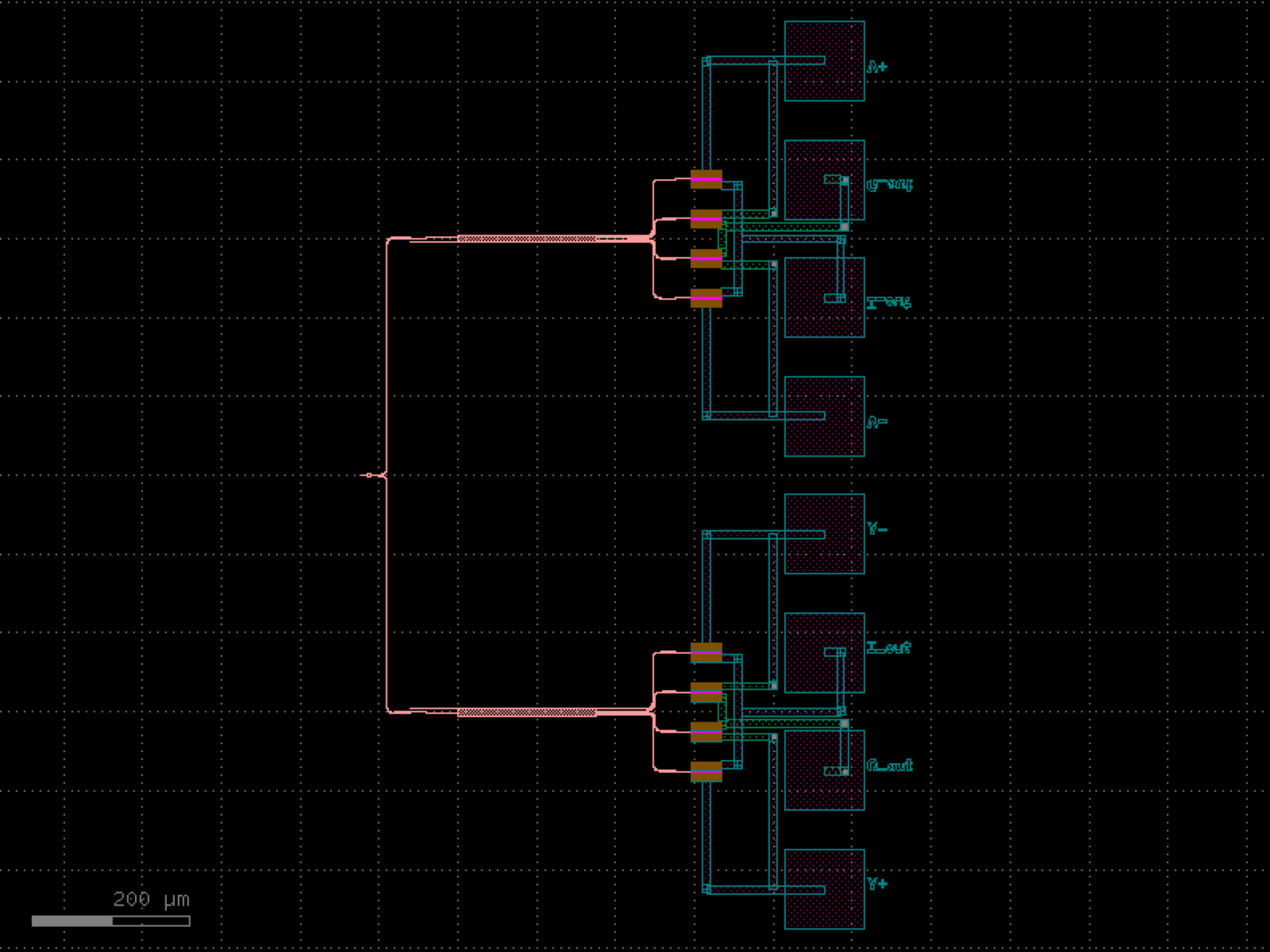
- gdsfactory.components.containers.add_fiber_array_optical_south_electrical_north(component='straight_heater_metal', pad='pad', grating_coupler='grating_coupler_te', cross_section_metal='metal_routing', with_loopback=True, pad_pitch=100.0, pitch=127.0, pad_gc_spacing=250.0, electrical_port_names=None, electrical_port_orientation=90, npads=None, port_types_grating_couplers=None, auto_taper_pads=True, **kwargs)[source]#
Returns a fiber array with Optical gratings on South and Electrical pads on North.
This a test configuration for DC pads.
- Parameters:
component (str | Callable[[...], Component] | dict[str, Any] | DKCell | partial[Component]) – component spec to add fiber and pads.
pad (str | Callable[[...], Component] | dict[str, Any] | DKCell | partial[Component]) – pad spec.
grating_coupler (str | Callable[[...], Component] | dict[str, Any] | DKCell | partial[Component]) – grating coupler function.
cross_section_metal (CrossSection | str | dict[str, Any] | Callable[[...], CrossSection] | SymmetricalCrossSection | DCrossSection) – metal cross section.
with_loopback (bool) – whether to add a loopback port.
pad_pitch (float) – spacing between pads.
pitch (float) – spacing between grating couplers.
pad_gc_spacing (float) – spacing between pads and grating couplers.
electrical_port_names (list[str] | None) – list of electrical port names. Defaults to all.
electrical_port_orientation (float | None) – orientation of electrical ports. Defaults to 90.
npads (int | None) – number of pads. Defaults to one per electrical_port_names.
port_types_grating_couplers (list[str] | None) – port types for grating couplers. Defaults to vertical TE, TM, and dual.
auto_taper_pads (bool) – whether to add a taper to the pads.
kwargs (Any) – additional arguments.
- Keyword Arguments:
layer_label – layer for settings label.
measurement – measurement name.
measurement_settings – measurement settings.
analysis – analysis name.
doe – Design of Experiment.
anchor – anchor point for the label. Defaults to south-west “sw”. Valid options are: “n”, “s”, “e”, “w”, “ne”, “nw”, “se”, “sw”, “c”.
gc_port_name – grating coupler input port name.
gc_port_labels – grating coupler list of labels.
component_name – optional for the label.
select_ports – function to select ports.
cross_section – cross_section function.
get_input_labels_function – function to get input labels. None skips labels.
layer_label – optional layer for grating coupler label.
bend – bend spec.
straight – straight spec.
taper – taper spec.
get_input_label_text_loopback_function – function to get input label test.
get_input_label_text_function – for labels.
fanout_length – if None, automatic calculation of fanout length.
max_y0_optical – in um.
with_loopback – True, adds loopback structures.
straight_separation – from edge to edge.
list_port_labels – None, adds TM labels to port indices in this list.
connected_port_list_ids – names of ports only for type 0 optical routing.
nb_optical_ports_lines – number of grating coupler lines.
force_manhattan – False
excluded_ports – list of port names to exclude when adding gratings.
grating_indices – list of grating coupler indices.
routing_straight – function to route.
routing_method – route_bundle.
gc_rotation – fiber coupler rotation in degrees. Defaults to -90.
input_port_indexes – to connect.
- Return type:
import gdsfactory as gf

gf.gpdk.PDK.activate()

c = gf.components.add_fiber_array_optical_south_electrical_north(component='straight_heater_metal', pad='pad', grating_coupler='grating_coupler_te', cross_section_metal='metal_routing', with_loopback=True, pad_pitch=100, pitch=127, pad_gc_spacing=250, electrical_port_orientation=90, auto_taper_pads=True).copy()
c.draw_ports()
c.plot()
(Source code, png, hires.png, pdf)
- gdsfactory.components.containers.add_termination(component='straight', port_names=None, terminator=functools.partial(<function taper>, width2=0.1), terminator_port_name=None)[source]#
Returns component with terminator on some ports.
- Parameters:
component (ComponentSpec) – to add terminator.
port_names (tuple[str, ...] | None) – ports to add terminator.
terminator (ComponentSpec) – factory for the terminator.
terminator_port_name (str | None) – for the terminator to connect to the component ports.
- Return type:
import gdsfactory as gf

gf.gpdk.PDK.activate()

c = gf.components.add_termination(component='straight').copy()
c.draw_ports()
c.plot()
(Source code, png, hires.png, pdf)
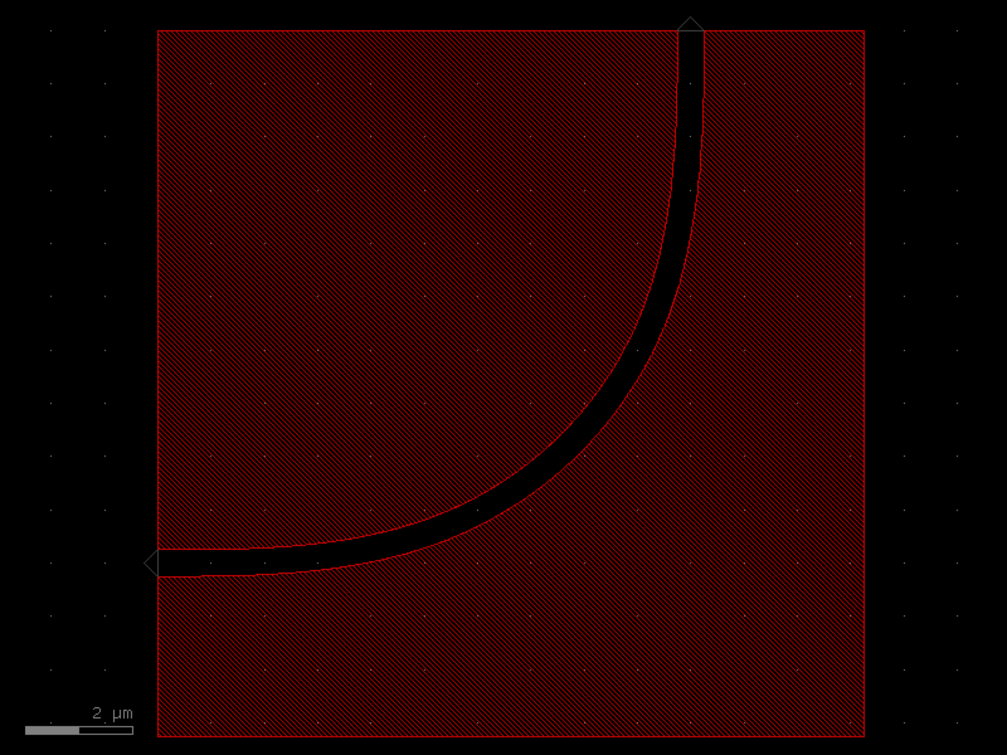
- gdsfactory.components.containers.add_trenches(component='coupler', layer_component='WG', layer_trench='DEEP_ETCH', width_trench=2.0, cross_section=None, top=None, bot=None, right=0, left=0)[source]#
Return inverted component with trenches.
- Parameters:
component (ComponentSpec) – component to add to the trenches.
layer_component (LayerSpec) – layer of the component to invert.
layer_trench (LayerSpec) – layer of the trenches.
width_trench (float) – width of the trenches.
cross_section (CrossSectionSpec | None) – spec (CrossSection, string or dict).
top (float | None) – width of the trench on the top. If None uses width_trench.
bot (float | None) – width of the trench on the bottom. If None uses width_trench.
right (float | None) – width of the trench on the right. If None uses width_trench.
left (float | None) – width of the trench on the left. If None uses width_trench.
- Return type:
gf.Component
import gdsfactory as gf

gf.gpdk.PDK.activate()

c = gf.components.add_trenches(component='coupler', layer_component='WG', layer_trench='DEEP_ETCH', width_trench=2, right=0, left=0).copy()
c.draw_ports()
c.plot()
(Source code, png, hires.png, pdf)
- gdsfactory.components.containers.add_trenches90(*, component='bend_euler', layer_component='WG', layer_trench='DEEP_ETCH', width_trench=2.0, cross_section=None, top=0, bot=None, right=None, left=0)#
Return inverted component with trenches.
- Parameters:
component (ComponentSpec) – component to add to the trenches.
layer_component (LayerSpec) – layer of the component to invert.
layer_trench (LayerSpec) – layer of the trenches.
width_trench (float) – width of the trenches.
cross_section (CrossSectionSpec | None) – spec (CrossSection, string or dict).
top (float | None) – width of the trench on the top. If None uses width_trench.
bot (float | None) – width of the trench on the bottom. If None uses width_trench.
right (float | None) – width of the trench on the right. If None uses width_trench.
left (float | None) – width of the trench on the left. If None uses width_trench.
- Return type:
gf.Component
import gdsfactory as gf

gf.gpdk.PDK.activate()

c = gf.components.add_trenches90(component='bend_euler', layer_component='WG', layer_trench='DEEP_ETCH', width_trench=2, top=0, left=0).copy()
c.draw_ports()
c.plot()
(Source code, png, hires.png, pdf)

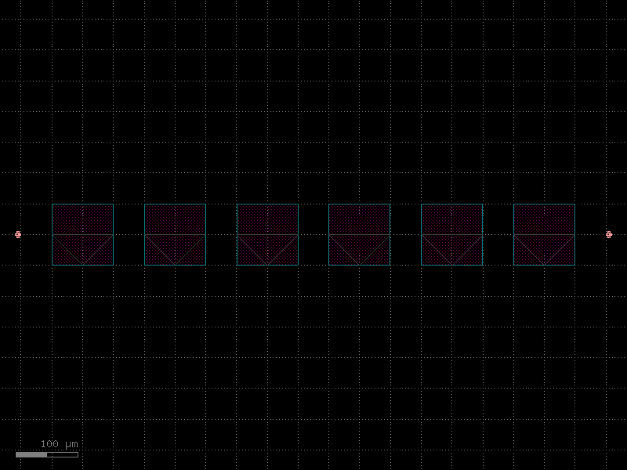
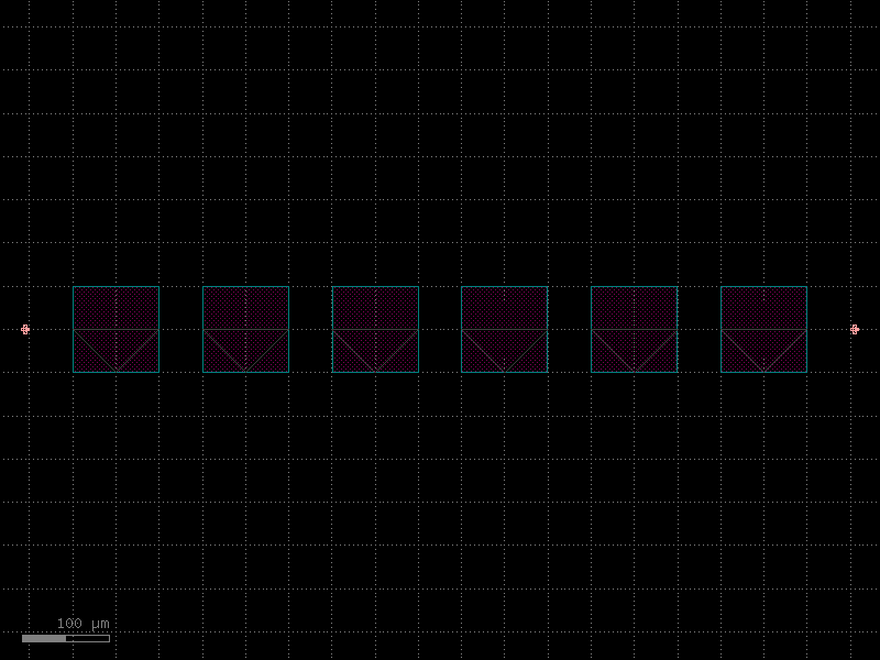
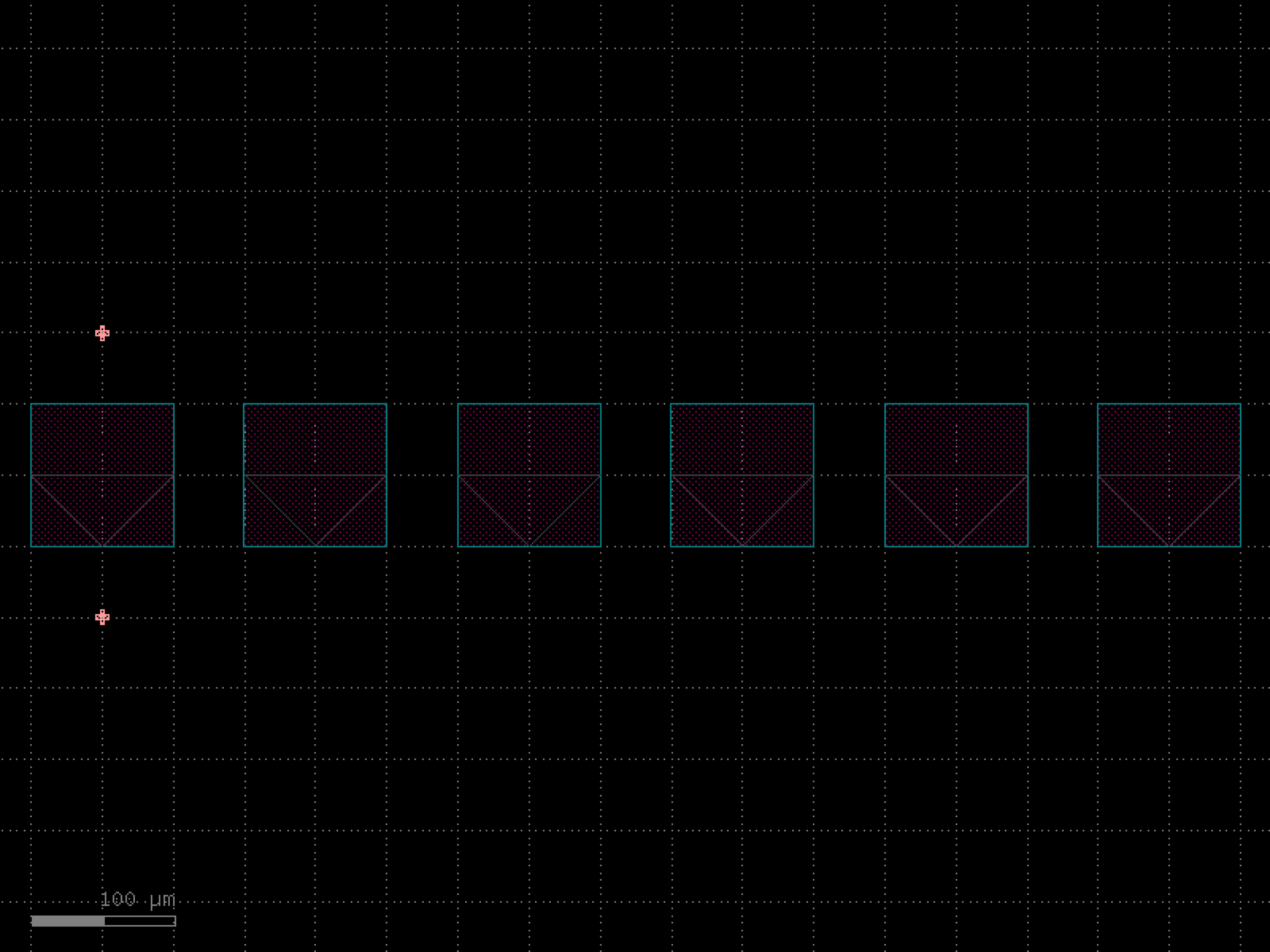
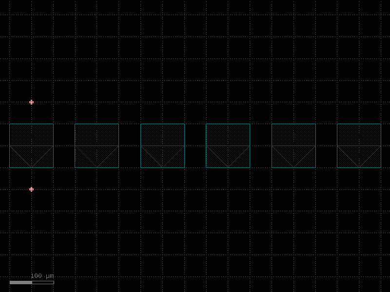
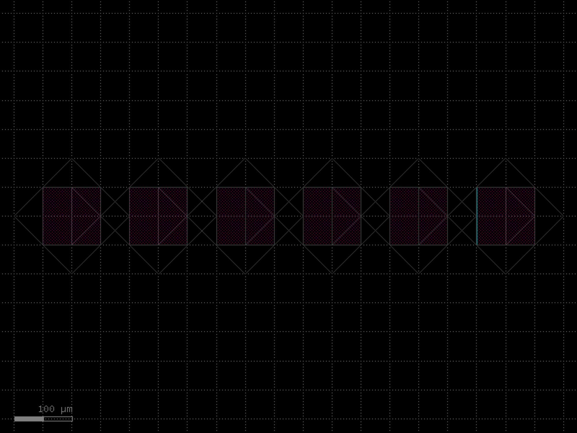
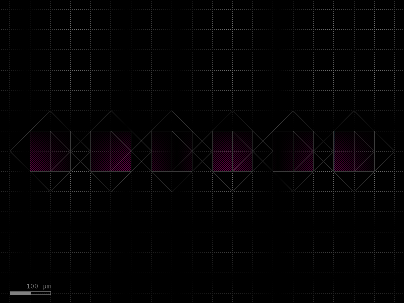
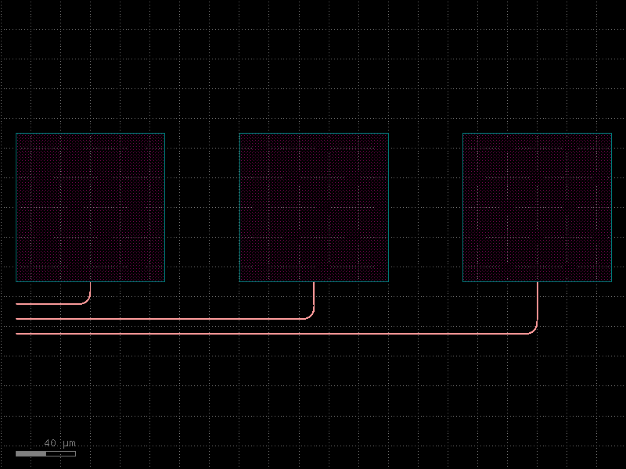
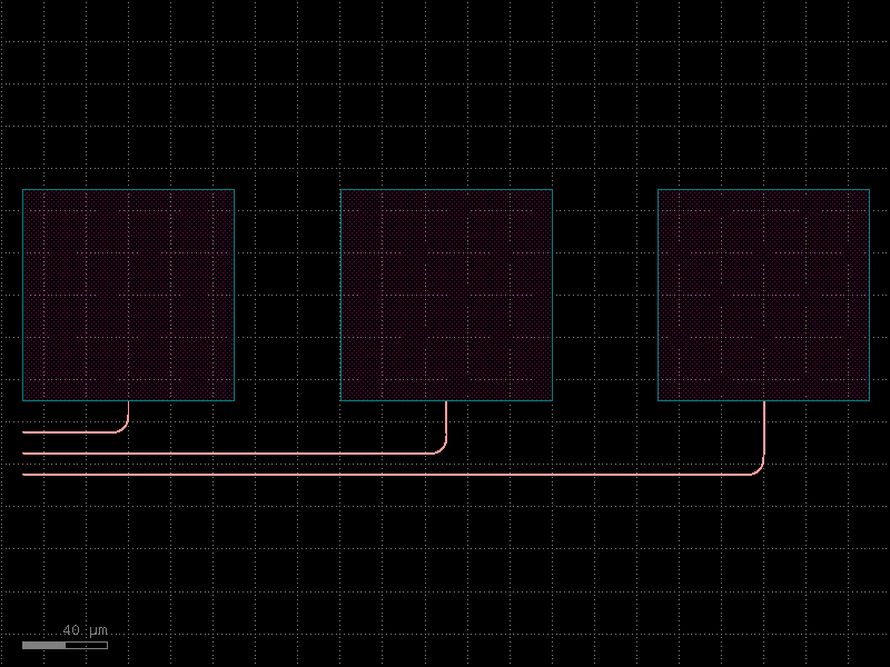
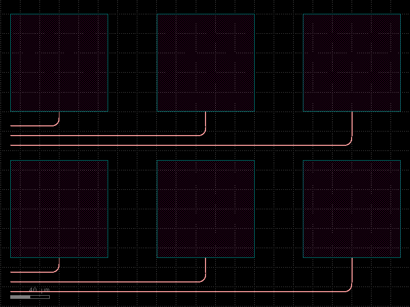
- gdsfactory.components.containers.array(component='pad', columns=6, rows=1, column_pitch=150, row_pitch=150, add_ports=True, size=None, centered=False, post_process=None, auto_rename_ports=False)[source]#
Returns an array of components.
- Parameters:
component (ComponentSpec) – to replicate.
columns (int) – in x.
rows (int) – in y.
column_pitch (float) – pitch between columns.
row_pitch (float) – pitch between rows.
auto_rename_ports (bool) – True to auto rename ports.
add_ports (bool) – add ports from component into the array.
size (tuple[float, float] | None) – Optional x, y size. Overrides columns and rows.
centered (bool) – center the array around the origin.
post_process (Sequence[_PostProcess | Callable[[Component], None] | partial[Component]] | None) – function to apply to the array after creation.
- Raises:
ValueError – If columns > 1 and spacing[0] = 0.
ValueError – If rows > 1 and spacing[1] = 0.
- Return type:
2 rows x 4 columns

  column_pitch
  <---------->
 ___        ___       ___        ___
|   |      |   |     |   |      |   |
|___|      |___|     |___|      |___|

 ___        ___       ___        ___
|   |      |   |     |   |      |   |
|___|      |___|     |___|      |___|
import gdsfactory as gf

gf.gpdk.PDK.activate()

c = gf.components.array(component='pad', columns=6, rows=1, column_pitch=150, row_pitch=150, add_ports=True, centered=False, auto_rename_ports=False).copy()
c.draw_ports()
c.plot()
(Source code, png, hires.png, pdf)

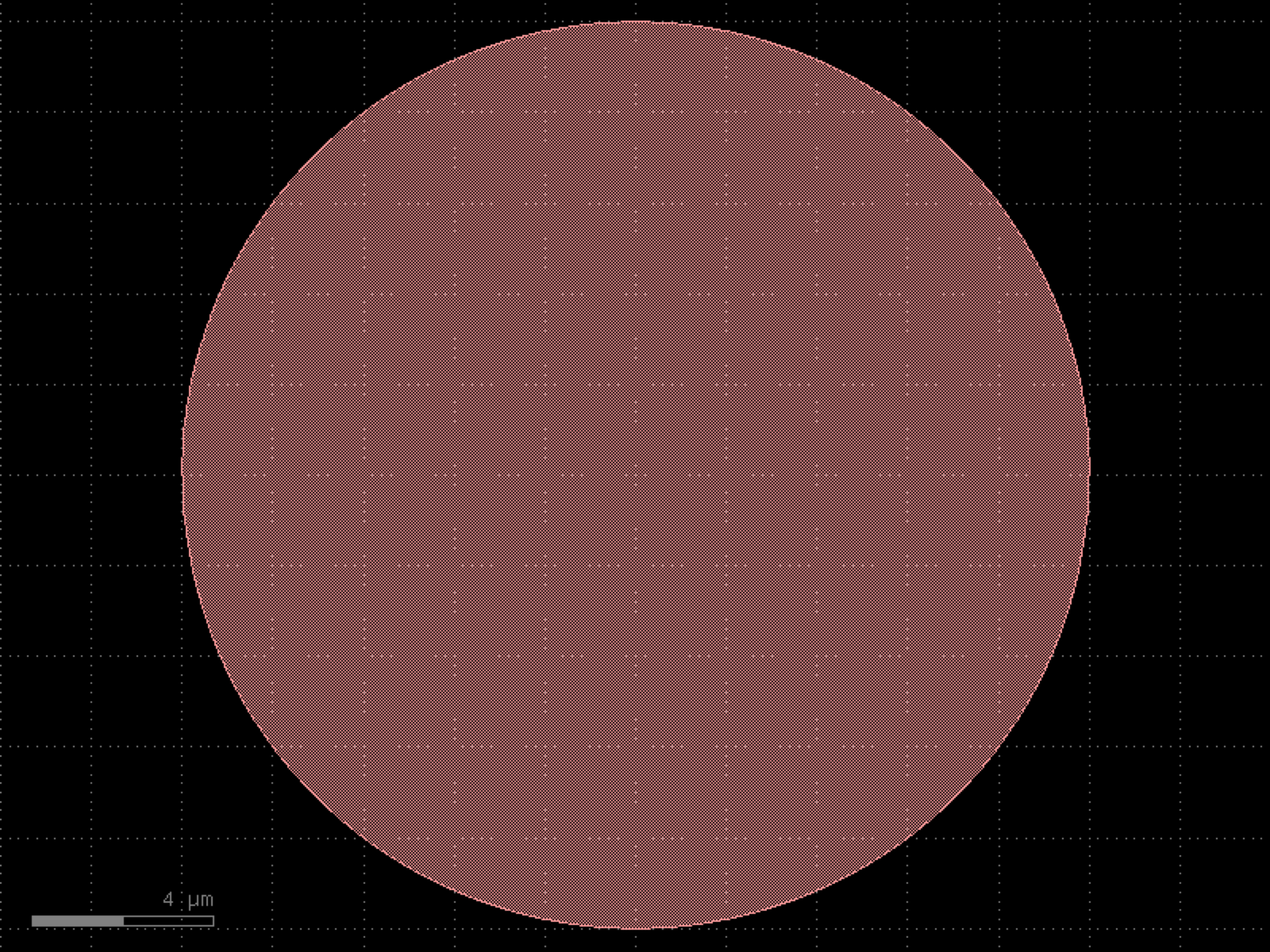
- gdsfactory.components.containers.array_hexagonal(component='circle', columns=10, rows=10, pitch=25.0, centered=True, add_ports=True)[source]#
Returns a hexagonal close-packed array of components.
Even rows are placed normally, odd rows are offset by pitch/2. Row spacing is pitch * sqrt(3)/2.
- Parameters:
component (ComponentSpec) – component to replicate.
columns (int) – number of columns.
rows (int) – number of rows.
pitch (float) – spacing between adjacent elements.
centered (bool) – center the array around the origin.
add_ports (bool) – add ports from each element.
- Return type:
import gdsfactory as gf

gf.gpdk.PDK.activate()

c = gf.components.array_hexagonal(component='circle', columns=10, rows=10, pitch=25, centered=True, add_ports=True).copy()
c.draw_ports()
c.plot()
(Source code, png, hires.png, pdf)

- gdsfactory.components.containers.array_polar(component='C', n_items=6, radius=50.0, start_angle=0.0, end_angle=360.0, rotate_items=True, add_ports=True)[source]#
Returns a polar/circular array of components.
Places component refs at equal angular intervals around a circle.
- Parameters:
component (ComponentSpec) – component to replicate.
n_items (int) – number of items in the array.
radius (float) – radius of the circle.
start_angle (float) – starting angle in degrees.
end_angle (float) – ending angle in degrees.
rotate_items (bool) – if True, rotate each item to point radially outward.
add_ports (bool) – add ports from each element.
- Return type:
import gdsfactory as gf

gf.gpdk.PDK.activate()

c = gf.components.array_polar(component='C', n_items=6, radius=50, start_angle=0, end_angle=360, rotate_items=True, add_ports=True).copy()
c.draw_ports()
c.plot()
(Source code, png, hires.png, pdf)

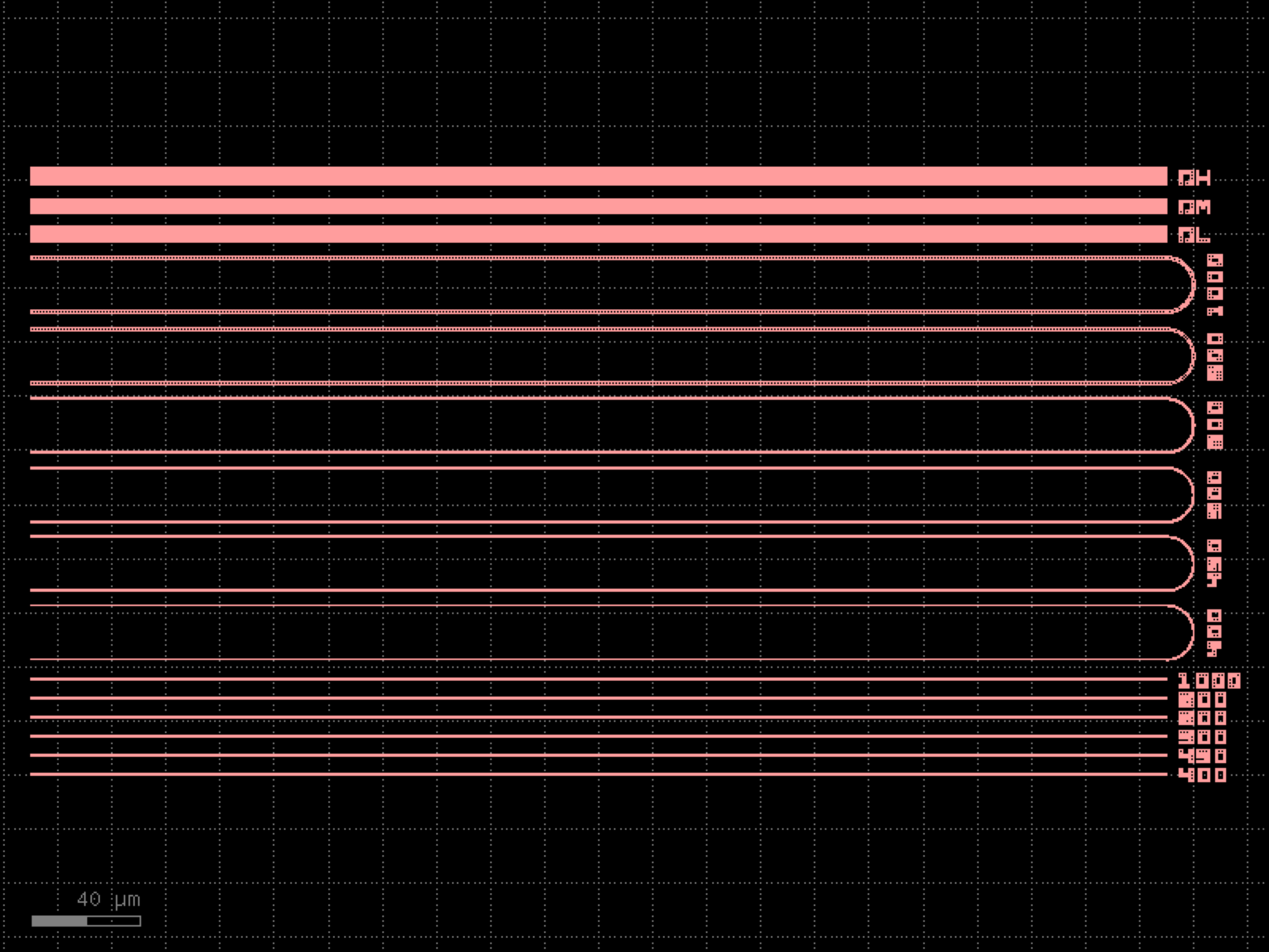
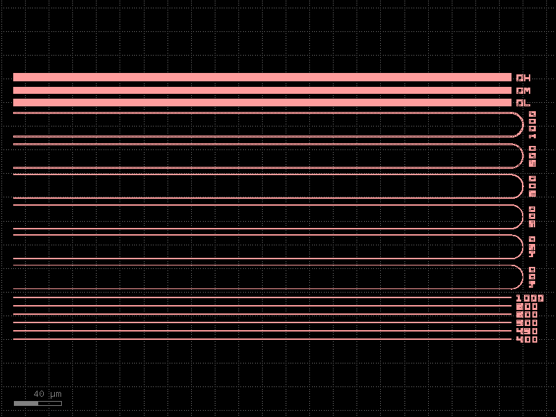
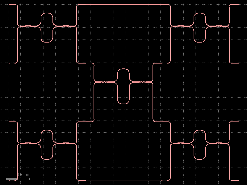
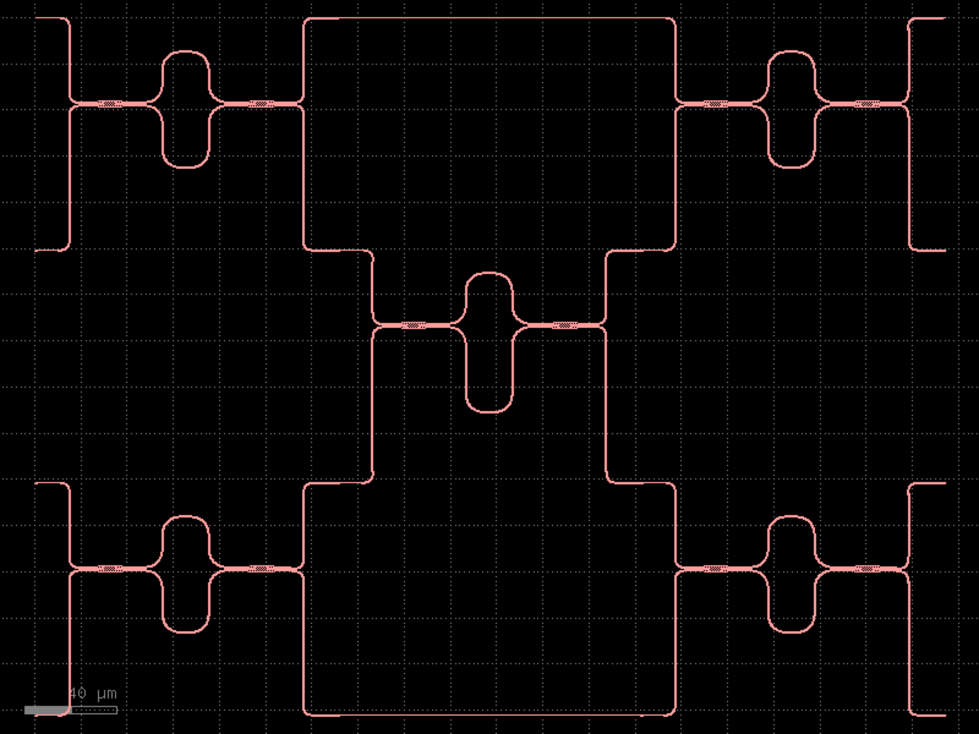
- gdsfactory.components.containers.component_sequence(sequence, symbol_to_component, ports_map=None, port_name1='o1', port_name2='o2', start_orientation=0.0, **kwargs)[source]#
Returns component from ASCII sequence.
if you prefix a symbol with ! it mirrors the component
- Parameters:
sequence (str) – a string or a list of symbols.
symbol_to_component (dict[str, tuple[Component, str, str]]) – maps symbols to (component, input, output).
ports_map (dict[str, tuple[str, str]] | None) – (optional) extra port mapping using the convention. {port_name: (alias_name, port_name)}
port_name1 (str) – input port_name.
port_name2 (str) – output port_name.
start_orientation (float) – in degrees.
**kwargs (Any) – additional keyword arguments passed to the connect method.
- Returns:
- containing the sequence of sub-components
instantiated and connected together in the sequence order.
- Return type:
component
import gdsfactory as gf

bend180 = gf.components.bend_circular180()
wg_pin = gf.components.straight_pin(length=40)
wg = gf.components.straight()

# Define a map between symbols and (component, input port, output port)
symbol_to_component = {
    "A": (bend180, 'o1', 'o2'),
    "B": (bend180, 'o2', 'o1'),
    "H": (wg_pin, 'o1', 'o2'),
    "-": (wg, 'o1', 'o2'),
}

# Each character in the sequence represents a component
s = "AB-H-H-H-H-BA"
c = gf.components.component_sequence(sequence=s, symbol_to_component=symbol_to_component)
c.plot()
(
Source code,png,hires.png,pdf)
- gdsfactory.components.containers.copy_layers(factory='cross', layers=((1, 0), (2, 0)), flatten=False, **kwargs)[source]#
Returns a component with the geometry copied in different layers.
- Parameters:
factory (ComponentSpec) – component spec.
layers (LayerSpecs) – iterable of layers.
flatten (bool) – flatten the result.
kwargs (Any) – keyword arguments passed to the component.
- Return type:
import gdsfactory as gf

gf.gpdk.PDK.activate()

c = gf.components.copy_layers(factory='cross', layers=((1, 0), (2, 0)), flatten=False).copy()
c.draw_ports()
c.plot()
(Source code, png, hires.png, pdf)

- gdsfactory.components.containers.extend_ports(component='mmi1x2', port_names=None, length=5.0, extension=None, port1=None, port2=None, port_type='optical', centered=False, cross_section=None, extension_port_names=None, allow_width_mismatch=False, auto_taper=True, **kwargs)[source]#
Returns a new component with some ports extended.
You can define extension Spec defaults to port cross_section of each port to extend.
- Parameters:
component (ComponentSpec) – component to extend ports.
port_names (PortNames | None) – list of ports names to extend, if None it extends all ports.
length (float) – extension length.
extension (ComponentSpec | None) – function to extend ports (defaults to a straight).
port1 (str | None) – extension input port name.
port2 (str | None) – extension output port name.
port_type (str) – type of the ports to extend.
centered (bool) – if True centers rectangle at (0, 0).
cross_section (CrossSectionSpec | None) – extension cross_section, defaults to port cross_section if port has no cross_section it creates one using width and layer.
extension_port_names (list[str] | None) – extension port names add to the new component.
allow_width_mismatch (bool) – allow width mismatches.
auto_taper (bool) – if True adds automatic tapers.
kwargs (Any) – cross_section settings.
- Keyword Arguments:
layer – port GDS layer.
prefix – port name prefix.
orientation – in degrees.
width – port width.
layers_excluded – List of layers to exclude.
port_type – optical, electrical, ….
clockwise – if True, sort ports clockwise, False: counter-clockwise.
- Return type:
import gdsfactory as gf

gf.gpdk.PDK.activate()

c = gf.components.extend_ports(component='mmi1x2', length=5, port_type='optical', centered=False, allow_width_mismatch=False, auto_taper=True).copy()
c.draw_ports()
c.plot()
(Source code, png, hires.png, pdf)
- gdsfactory.components.containers.extend_ports_list(component_spec, extension, extension_port_name=None, ignore_ports=None)[source]#
Returns a component with an extension attached to a list of ports.
- Parameters:
component_spec (ComponentSpec) – component from which to get ports.
extension (ComponentSpec) – function for extension.
extension_port_name (str | None) – to connect extension.
ignore_ports (Sequence[str] | None) – list of port names to ignore.
- Return type:
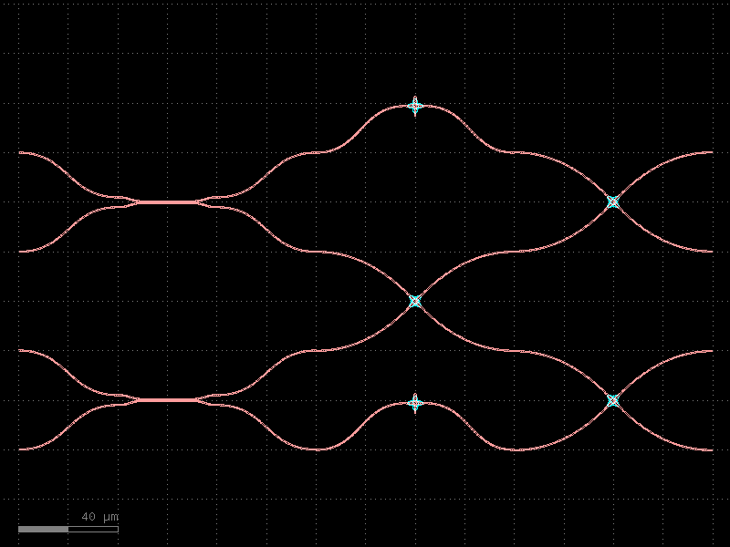
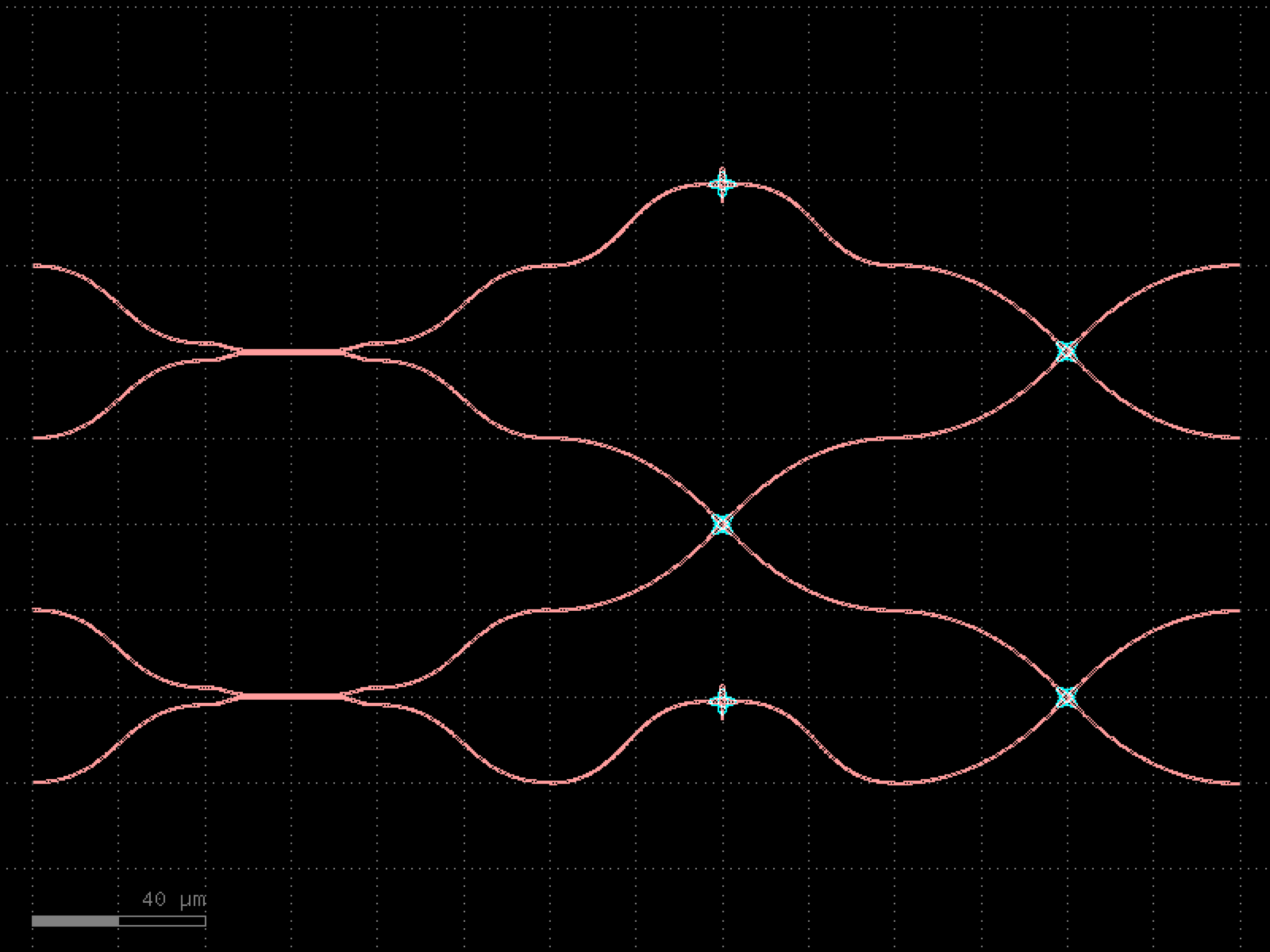
- gdsfactory.components.containers.splitter_chain(splitter='mmi1x2', columns=3, bend='bend_s')[source]#
Chain of splitters.
- Parameters:
splitter (ComponentSpec) – splitter to chain.
columns (int) – number of splitters to chain.
bend (ComponentSpec) – bend to connect splitters.
- Return type:
           __o5
        __|
     __|  |__o4
o1 _|  |__o3
    |__o2

     __o2
o1 _|
    |__o3
import gdsfactory as gf

gf.gpdk.PDK.activate()

c = gf.components.splitter_chain(splitter='mmi1x2', columns=3, bend='bend_s').copy()
c.draw_ports()
c.plot()
(Source code, png, hires.png, pdf)

- gdsfactory.components.containers.splitter_tree(coupler='mmi1x2', noutputs=4, spacing=(90.0, 50.0), bend_s='bend_s', bend_s_xsize=None, cross_section='strip')[source]#
Tree of power splitters.
- Parameters:
coupler (ComponentSpec) – coupler factory.
noutputs (int) – number of outputs.
spacing (Spacing) – x, y spacing between couplers.
bend_s (ComponentSpec | None) – Sbend function for termination.
bend_s_xsize (float | None) – xsize for the sbend.
cross_section (CrossSectionSpec) – cross_section.
- Return type:
gf.Component
     __|
  __|  |__
_|  |__
 |__        dy

  dx
import gdsfactory as gf

gf.gpdk.PDK.activate()

c = gf.components.splitter_tree(coupler='mmi1x2', noutputs=4, spacing=(90, 50), bend_s='bend_s', cross_section='strip').copy()
c.draw_ports()
c.plot()
(Source code, png, hires.png, pdf)

- gdsfactory.components.containers.switch_tree(*, coupler=functools.partial(<function mzi>, combiner='mmi2x2', port_e1_combiner='o3', port_e0_combiner='o4', delta_length=0, straight_x_top='straight_heater_metal', length_x=None), noutputs=4, spacing=(500, 100), bend_s='bend_s', bend_s_xsize=None, cross_section='strip')#
Tree of power splitters.
- Parameters:
coupler (ComponentSpec) – coupler factory.
noutputs (int) – number of outputs.
spacing (Spacing) – x, y spacing between couplers.
bend_s (ComponentSpec | None) – Sbend function for termination.
bend_s_xsize (float | None) – xsize for the sbend.
cross_section (CrossSectionSpec) – cross_section.
- Return type:
gf.Component
     __|
  __|  |__
_|  |__
 |__        dy

  dx
import gdsfactory as gf

gf.gpdk.PDK.activate()

c = gf.components.switch_tree(noutputs=4, spacing=(500, 100), bend_s='bend_s', cross_section='strip').copy()
c.draw_ports()
c.plot()
(Source code, png, hires.png, pdf)

couplers#
- gdsfactory.components.couplers.coupler(gap=0.236, length=20.0, dy=4.0, dx=10.0, cross_section='strip', allow_min_radius_violation=False, bend='bend_s')[source]#
Symmetric coupler.
- Parameters:
gap (float) – between straights in um.
length (float) – of coupling region in um.
dy (float) – port to port vertical spacing in um.
dx (float) – length of bend in x direction in um.
cross_section (CrossSectionSpec) – spec (CrossSection, string or dict).
allow_min_radius_violation (bool) – if True does not check for min bend radius.
bend (ComponentSpec) – input and output sbend components.
- Return type:
      dx                                 dx
   |------|                           |------|
o2 ________                           ______o3
           \                         /           |
            \        length         /            |
             ======================= gap         | dy
            /                       \            |
   ________/                         \_______    |
o1                                          o4

               coupler_straight  coupler_symmetric
import gdsfactory as gf

gf.gpdk.PDK.activate()

c = gf.components.coupler(gap=0.236, length=20, dy=4, dx=10, cross_section='strip', allow_min_radius_violation=False, bend='bend_s').copy()
c.draw_ports()
c.plot()
(Source code, png, hires.png, pdf)

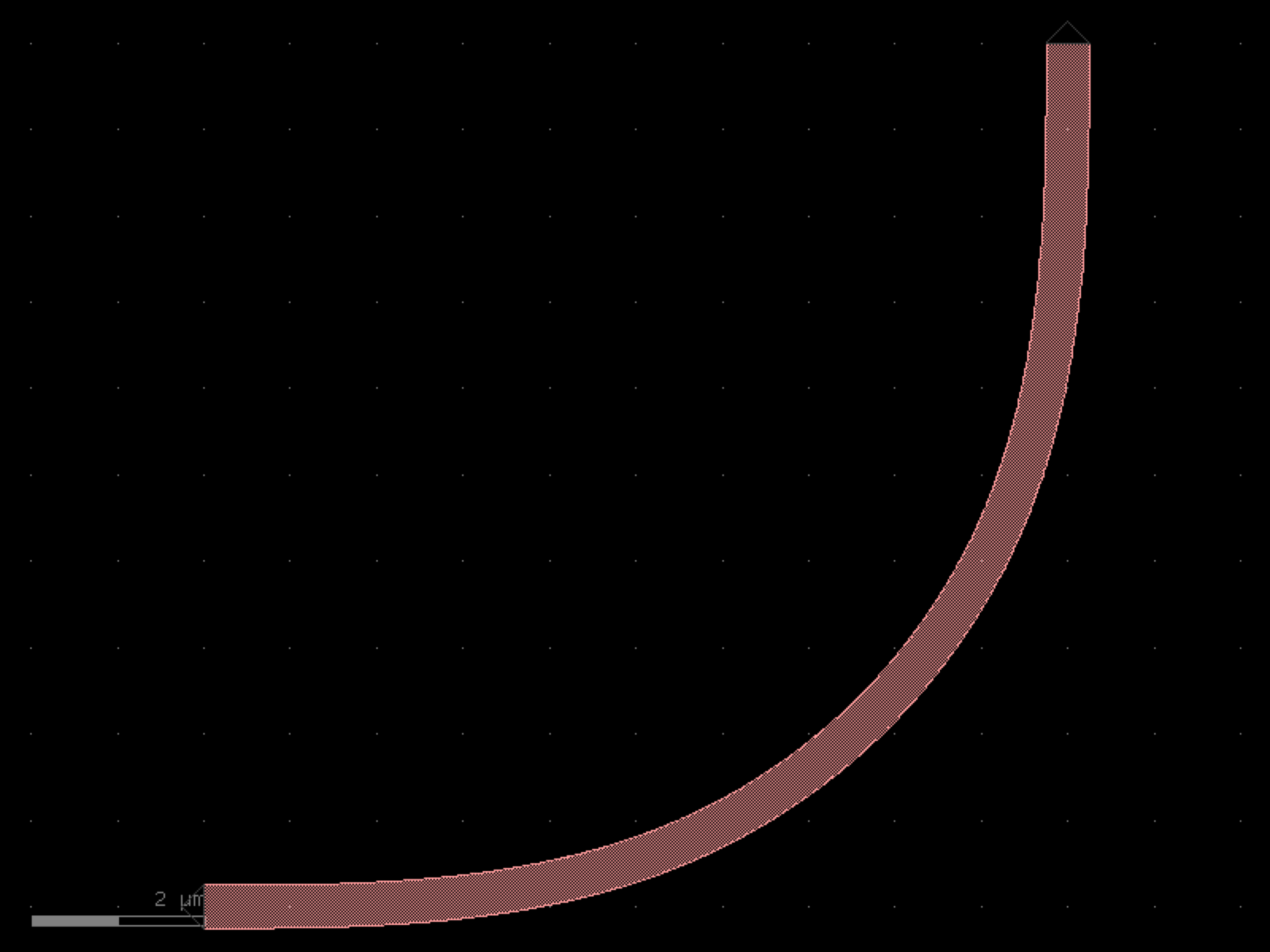
- gdsfactory.components.couplers.coupler90(gap=0.2, radius=None, bend='bend_euler', straight='straight', cross_section='strip', cross_section_bend=None, length_straight=None)[source]#
Straight coupled to a bend.
- Parameters:
gap (float) – um.
radius (float | None) – um.
straight (ComponentSpec) – for straight.
bend (ComponentSpec) – bend spec.
cross_section (CrossSectionSpec) – cross_section spec.
cross_section_bend (CrossSectionSpec | None) – optional bend cross_section spec.
length_straight (float | None) – optional length of the straight waveguide.
- Return type:
     o3
      |
     /
    /
o2_/
o1___o4
import gdsfactory as gf

gf.gpdk.PDK.activate()

c = gf.components.coupler90(gap=0.2, bend='bend_euler', straight='straight', cross_section='strip').copy()
c.draw_ports()
c.plot()
(Source code, png, hires.png, pdf)
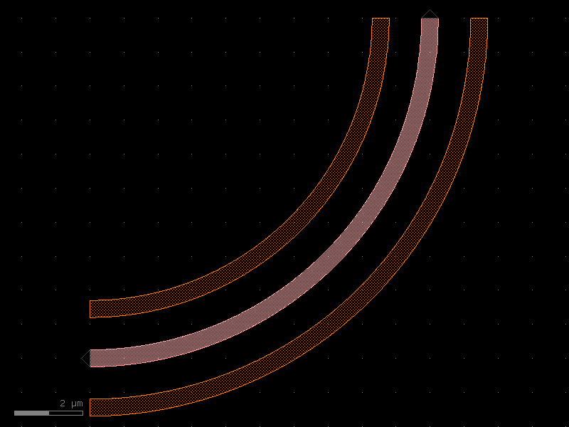
- gdsfactory.components.couplers.coupler90bend(radius=10.0, gap=0.2, bend='bend_euler', cross_section_inner='strip', cross_section_outer='strip')[source]#
Returns 2 coupled bends.
- Parameters:
radius (float) – um.
gap (float) – um.
bend (ComponentSpec) – for bend.
cross_section_inner (CrossSectionSpec) – spec inner bend.
cross_section_outer (CrossSectionSpec) – spec outer bend.
- Return type:
    r   3 4
    |   | |
    |  / /
    | / /
2____/ /
1_____/
import gdsfactory as gf

gf.gpdk.PDK.activate()

c = gf.components.coupler90bend(radius=10, gap=0.2, bend='bend_euler', cross_section_inner='strip', cross_section_outer='strip').copy()
c.draw_ports()
c.plot()
(Source code, png, hires.png, pdf)
- gdsfactory.components.couplers.coupler90circular(gap=0.2, radius=None, *, bend='bend_circular', straight='straight', cross_section='strip', cross_section_bend=None, length_straight=None)#
Straight coupled to a bend.
- Parameters:
gap (float) – um.
radius (float | None) – um.
straight (ComponentSpec) – for straight.
bend (ComponentSpec) – bend spec.
cross_section (CrossSectionSpec) – cross_section spec.
cross_section_bend (CrossSectionSpec | None) – optional bend cross_section spec.
length_straight (float | None) – optional length of the straight waveguide.
- Return type:
     o3
      |
     /
    /
o2_/
o1___o4
import gdsfactory as gf

gf.gpdk.PDK.activate()

c = gf.components.coupler90circular(gap=0.2, bend='bend_circular', straight='straight', cross_section='strip').copy()
c.draw_ports()
c.plot()
(Source code, png, hires.png, pdf)
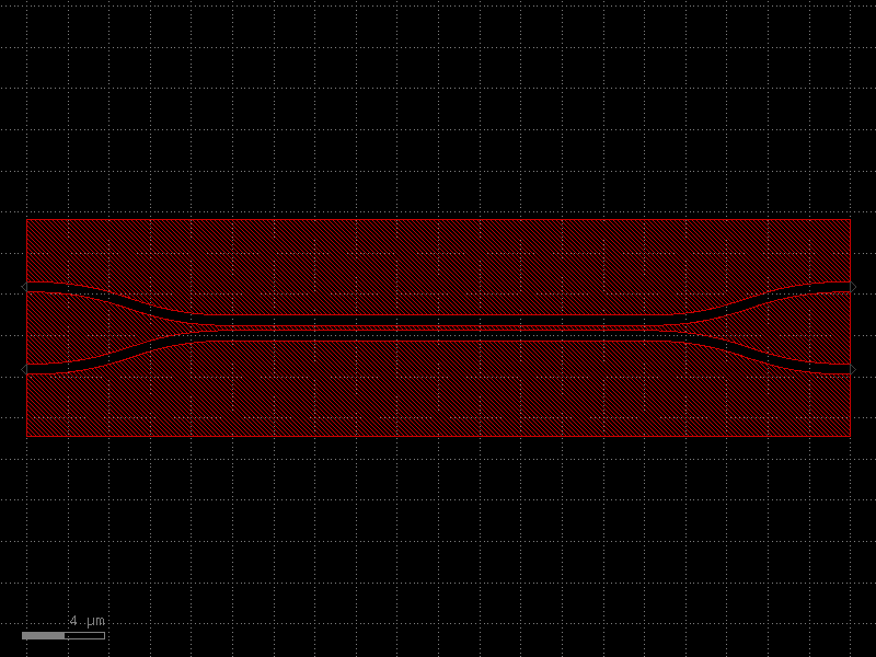
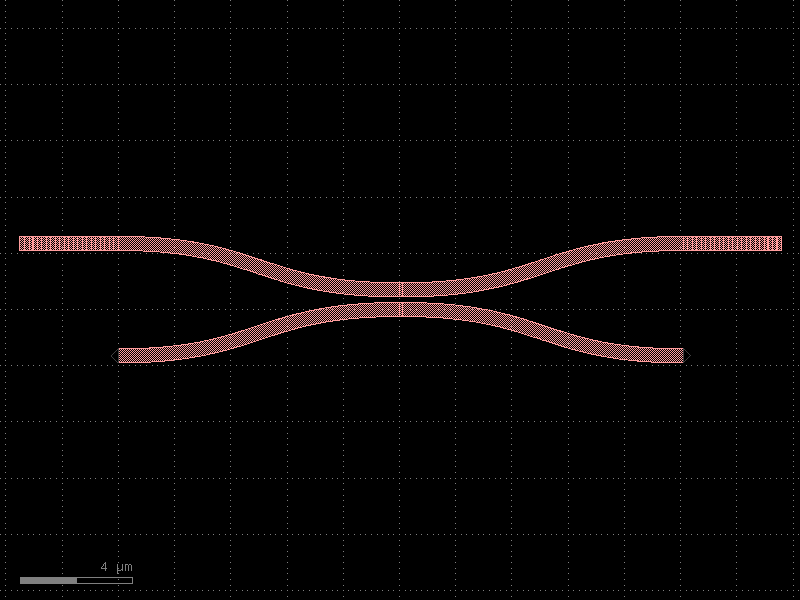
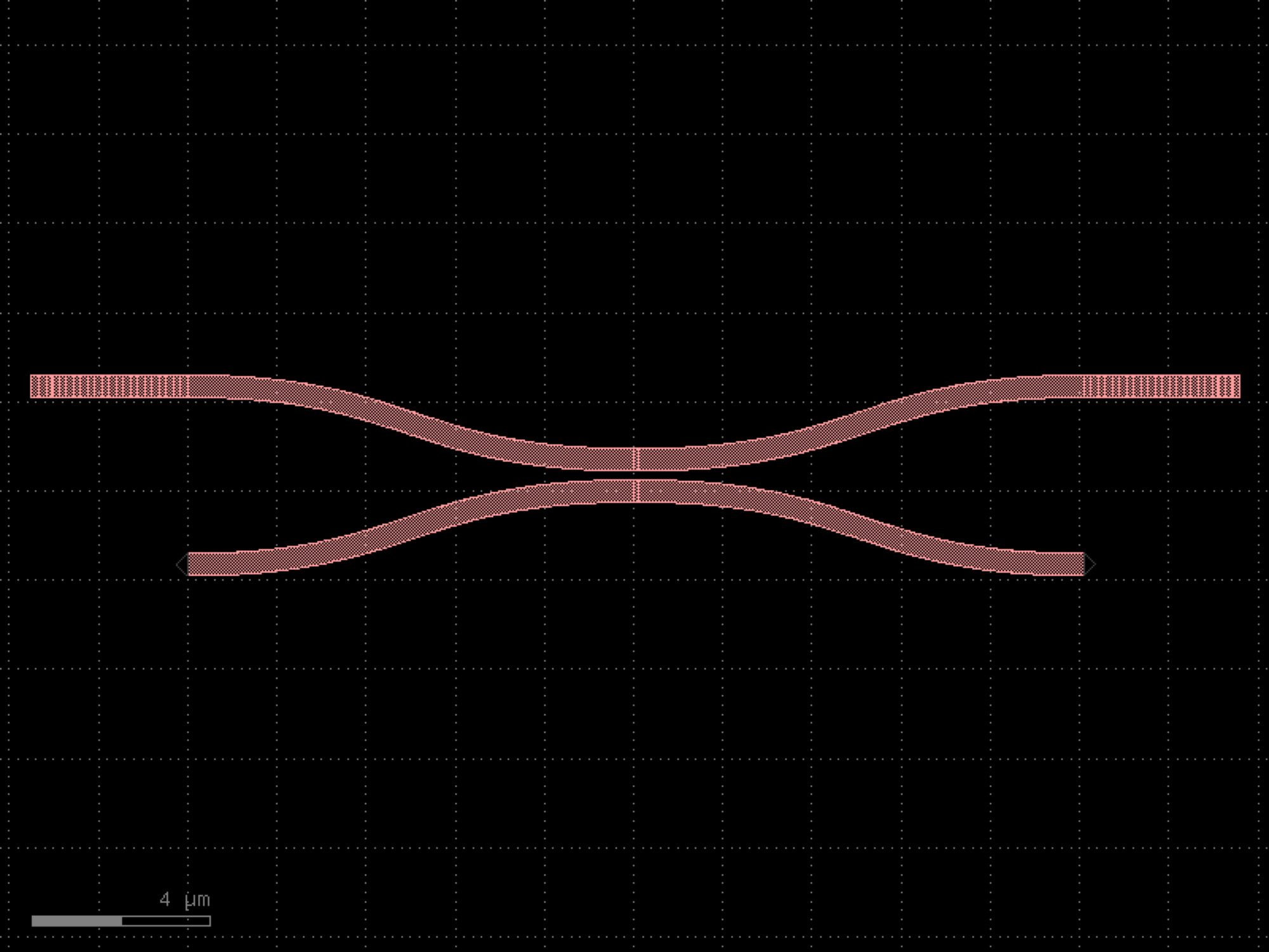
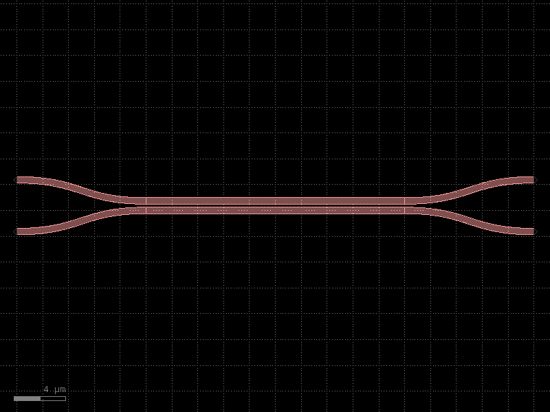
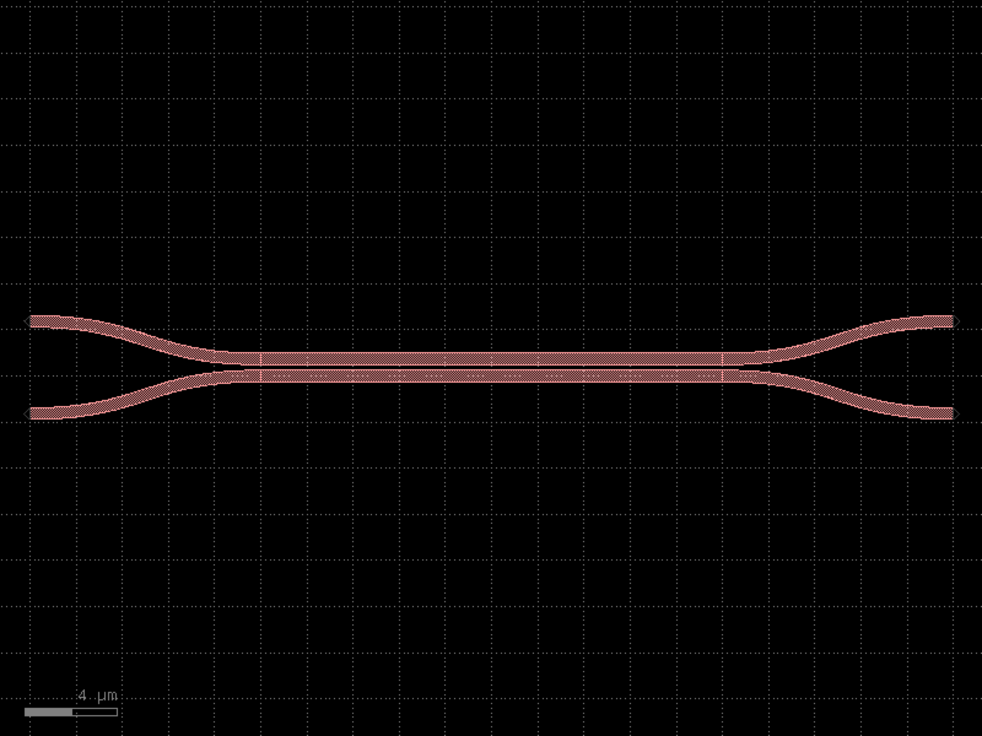
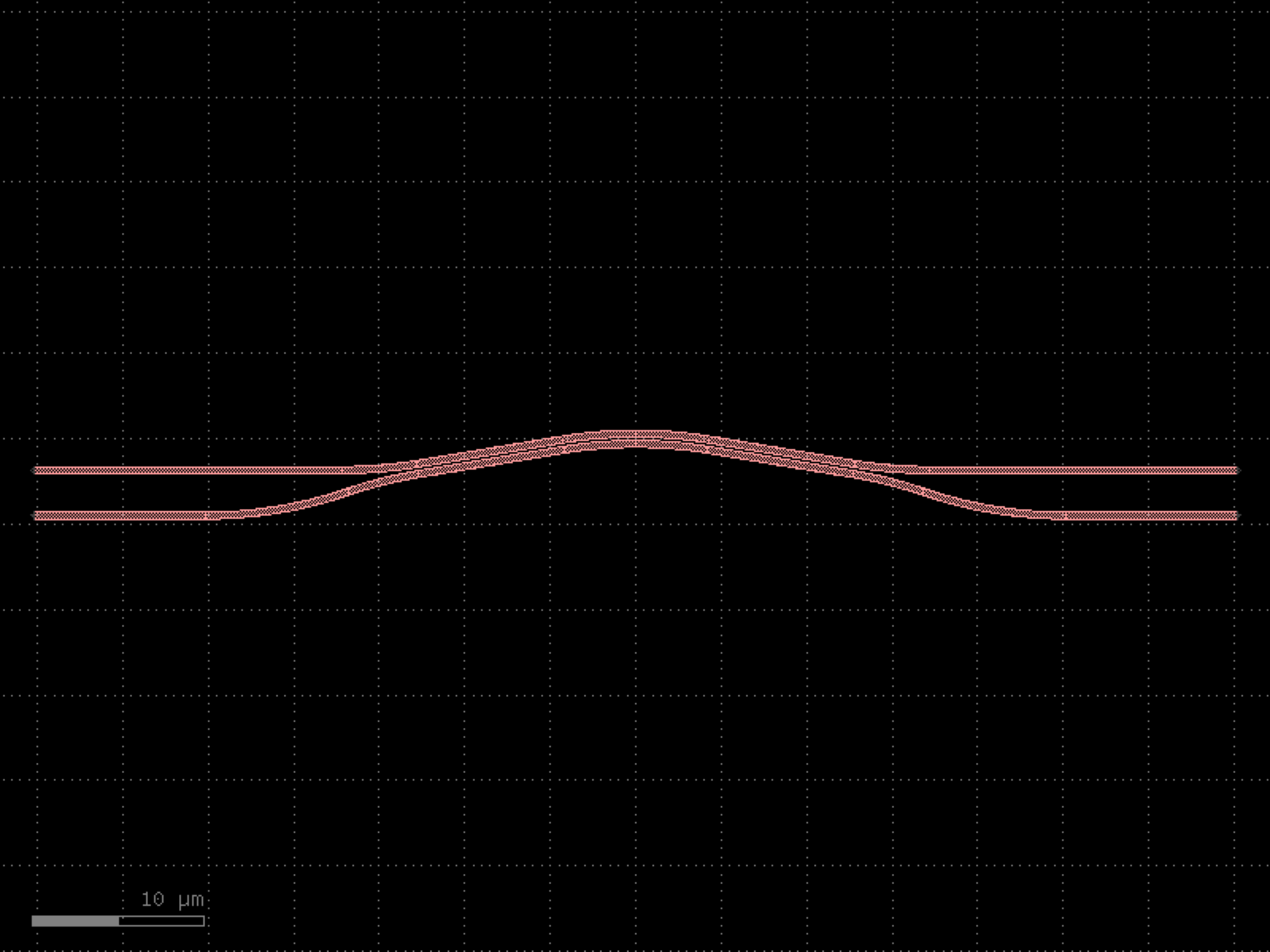
- gdsfactory.components.couplers.coupler_adiabatic(length1=20.0, length2=50.0, length3=30.0, wg_sep=1.0, input_wg_sep=3.0, output_wg_sep=3.0, dw=0.1, cross_section='strip')[source]#
Returns 50/50 adiabatic coupler.
Design based on asymmetric adiabatic 3dB coupler designs, such as those. - https://doi.org/10.1364/CLEO.2010.CThAA2, - https://doi.org/10.1364/CLEO_SI.2017.SF1I.5 - https://doi.org/10.1364/CLEO_SI.2018.STh4B.4
input Bezier curves, with poles set to half of the x-length of the S-bend. 1. is the first half of input S-bend where input widths taper by +dw and -dw 2. is the second half of the S-bend straight with constant, unbalanced widths 3. is the region where the two asymmetric straights gradually come together 4. straights taper back to the original width at a fixed distance from one another 5. is the output S-bend straight.
- Parameters:
length1 (float) – region that gradually brings the two asymmetric straights together. In this region the straight widths gradually change to be different by dw.
length2 (float) – coupling region, where asymmetric straights gradually become the same width.
length3 (float) – output region where the two straights separate.
wg_sep (float) – Distance between center-to-center in the coupling region (Region 2).
input_wg_sep (float) – Separation of the two straights at the input, center-to-center.
output_wg_sep (float) – Separation of the two straights at the output, center-to-center.
dw (float) – Change in straight width. In Region 1, top arm tapers to width+dw/2.0, bottom taper to width-dw/2.0.
cross_section (CrossSectionSpec) – cross_section spec.
- Return type:
import gdsfactory as gf

gf.gpdk.PDK.activate()

c = gf.components.coupler_adiabatic(length1=20, length2=50, length3=30, wg_sep=1, input_wg_sep=3, output_wg_sep=3, dw=0.1, cross_section='strip').copy()
c.draw_ports()
c.plot()
(Source code, png, hires.png, pdf)
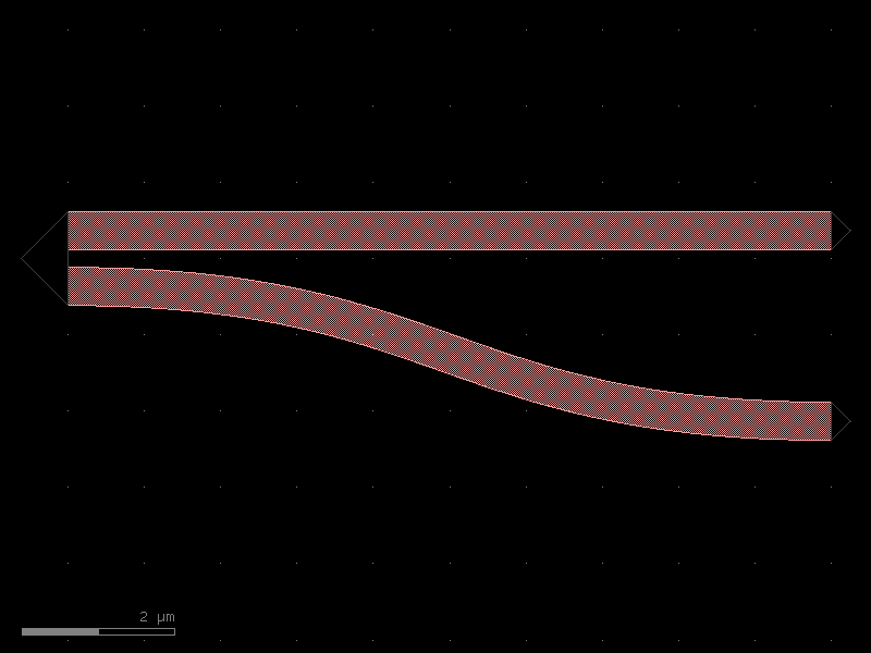
- gdsfactory.components.couplers.coupler_asymmetric(gap=0.234, dy=2.5, dx=10.0, cross_section='strip')[source]#
Bend coupled to straight waveguide.
- Parameters:
gap (float) – um.
dy (float) – port to port vertical spacing.
dx (float) – bend length in x direction.
cross_section (CrossSectionSpec) – spec.
- Return type:
               dx
            |-----|
             _____ o2
            /         |
      _____/          |
gap o1____________    |  dy
                   o3
import gdsfactory as gf

gf.gpdk.PDK.activate()

c = gf.components.coupler_asymmetric(gap=0.234, dy=2.5, dx=10, cross_section='strip').copy()
c.draw_ports()
c.plot()
(Source code, png, hires.png, pdf)

- gdsfactory.components.couplers.coupler_bent(gap=0.2, radius=26, length=8.6, width1=0.4, width2=0.4, length_straight=10, cross_section='strip')[source]#
Returns Broadband SOI curved / straight directional coupler.
based on: https://doi.org/10.1038/s41598-017-07618-6.
- Parameters:
gap (float) – gap.
radius (float) – radius coupling.
length (float) – coupler_length.
width1 (float) – width1.
width2 (float) – width2.
length_straight (float) – input and output straight length.
cross_section (str) – cross_section.
- Return type:
import gdsfactory as gf

gf.gpdk.PDK.activate()

c = gf.components.coupler_bent(gap=0.2, radius=26, length=8.6, width1=0.4, width2=0.4, length_straight=10, cross_section='strip').copy()
c.draw_ports()
c.plot()
(Source code, png, hires.png, pdf)
- gdsfactory.components.couplers.coupler_broadband(w_sc=0.5, gap_sc=0.2, w_top=0.6, gap_pc=0.3, legnth_taper=1.0, bend='bend_euler', coupler_straight='coupler_straight', length_coupler_straight=12.4, lenght_coupler_big_gap=4.7, cross_section='strip', radius=10.0)[source]#
Returns broadband coupler component.
https://docs.flexcompute.com/projects/tidy3d/en/latest/notebooks/BroadbandDirectionalCoupler.html proposed in Zeqin Lu, Han Yun, Yun Wang, Zhitian Chen, Fan Zhang, Nicolas A. F. Jaeger, and Lukas Chrostowski, “Broadband silicon photonic directional coupler using asymmetric-waveguide based phase control,” Opt. Express 23, 3795-3808 (2015), DOI: 10.1364/OE.23.003795.
- Parameters:
w_sc (float) – width of waveguides in the symmetric coupler section.
gap_sc (float) – gap size between the waveguides in the symmetric coupler section.
w_top (float) – width of the top waveguide in the phase control section.
gap_pc (float) – gap size in the phase control section.
legnth_taper (float) – length of the tapers.
bend (ComponentSpec) – bend factory.
coupler_straight (ComponentSpec) – coupler_straight factory.
length_coupler_straight (float) – optimal L_1 from the 3d fdtd analysis.
lenght_coupler_big_gap (float) – optimal L_2 from the 3d fdtd analysis.
cross_section (CrossSectionSpec) – cross_section of the waveguides.
radius (float) – bend radius.
- Return type:
import gdsfactory as gf

gf.gpdk.PDK.activate()

c = gf.components.coupler_broadband(w_sc=0.5, gap_sc=0.2, w_top=0.6, gap_pc=0.3, legnth_taper=1, bend='bend_euler', coupler_straight='coupler_straight', length_coupler_straight=12.4, lenght_coupler_big_gap=4.7, cross_section='strip', radius=10).copy()
c.draw_ports()
c.plot()
(Source code, png, hires.png, pdf)
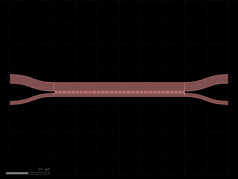
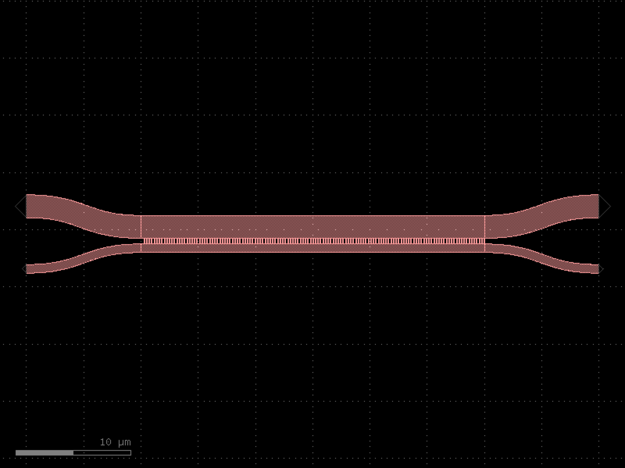
- gdsfactory.components.couplers.coupler_full(coupling_length=40.0, dx=10.0, dy=4.8, gap=0.5, dw=0.1, cross_section='strip', width=None)[source]#
Adiabatic Full coupler.
Design based on asymmetric adiabatic full coupler designs, such as the one reported in ‘Integrated Optic Adiabatic Devices on Silicon’ by Y. Shani, et al (IEEE Journal of Quantum Electronics, Vol. 27, No. 3 March 1991).
1. is the first half of the input S-bend straight where the input straights widths taper by +dw and -dw, 2. is the second half of the S-bend straight with constant, unbalanced widths, 3. is the coupling region where the straights from unbalanced widths to balanced widths to reverse polarity unbalanced widths, 4. is the fixed width straight that curves away from the coupling region, 5.is the final curve where the straights taper back to the regular width specified in the straight template.
- Parameters:
coupling_length (float) – Length of the coupling region in um.
dx (float) – Length of the bend regions in um.
dy (float) – Port-to-port distance between the bend regions in um.
gap (float) – Distance between the two straights in um.
dw (float) – delta width. Top arm tapers to width - dw, bottom to width + dw in um.
cross_section (CrossSectionSpec) – cross-section spec.
width (float | None) – width of the waveguide. If None, it will use the width of the cross_section.
- Return type:
import gdsfactory as gf

gf.gpdk.PDK.activate()

c = gf.components.coupler_full(coupling_length=40, dx=10, dy=4.8, gap=0.5, dw=0.1, cross_section='strip').copy()
c.draw_ports()
c.plot()
(Source code, png, hires.png, pdf)
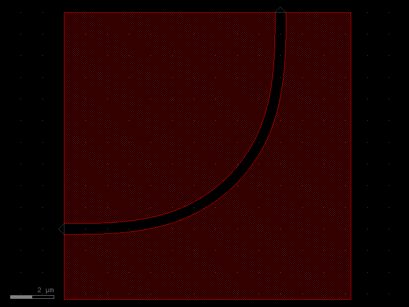
- gdsfactory.components.couplers.coupler_pulley(radius=10.0, ring_width=None, gap=0.2, coupling_angle=60.0, wg_length=40.0, wg_height=10.0, n_segments=128, cross_section='strip', layer='WG')[source]#
Returns a disc or ring with a pulley-coupled waveguide.
A waveguide wraps symmetrically around the top of a disc/ring over coupling_angle degrees. Bezier S-curves (following the CNST discPulley construction, eq. 2.22) route the waveguide from the coupling arc down to horizontal exits on both sides.
- Parameters:
radius (float) – radius of the disc, or outer radius of the ring.
ring_width (float | None) – width of the ring annulus. None for a solid disc.
gap (float) – gap between the waveguide inner edge and the disc/ring.
coupling_angle (float) – total wrap angle in degrees (symmetric about top).
wg_length (float) – horizontal half-length of the waveguide from the disc center to the exit end. Controls S-curve extent. Corresponds to CNST parameter L.
wg_height (float) – vertical drop from disc center to exit waveguide level. Corresponds to CNST parameter H.
n_segments (int) – number of points for each curved section.
cross_section (CrossSectionSpec) – cross-section spec for the coupling waveguide.
layer (LayerSpec) – layer spec for the disc/ring.
- Return type:
import gdsfactory as gf

gf.gpdk.PDK.activate()

c = gf.components.coupler_pulley(radius=10, gap=0.2, coupling_angle=60, wg_length=40, wg_height=10, n_segments=128, cross_section='strip', layer='WG').copy()
c.draw_ports()
c.plot()
(Source code, png, hires.png, pdf)

- gdsfactory.components.couplers.coupler_ring(gap=0.2, radius=None, length_x=4.0, bend='bend_euler', straight='straight', cross_section='strip', cross_section_bend=None, length_extension=None)[source]#
Coupler for ring.
- Parameters:
gap (float) – spacing between parallel coupled straight waveguides.
radius (float | None) – of the bends. Default is None, which uses the default radius of the cross_section.
length_x (float) – length of the parallel coupled straight waveguides.
bend (ComponentSpec) – 90 degrees bend spec.
straight (ComponentSpec) – straight spec.
cross_section (CrossSectionSpec) – cross_section spec.
cross_section_bend (CrossSectionSpec | None) – optional bend cross_section spec.
length_extension (float | None) – straight length extension at the end of the coupler bottom ports.
- Return type:
o2                              o3
xx                              xx
xx                             xx
 xx          length_x          x
  xx     ◄───────────────►    x
   xx                       xxx
     xx                   xxx
      xxx──────▲─────────xxx
               │gap
       o1──────▼─────────◄──────────────► o4
                          length_extension
import gdsfactory as gf

gf.gpdk.PDK.activate()

c = gf.components.coupler_ring(gap=0.2, length_x=4, bend='bend_euler', straight='straight', cross_section='strip').copy()
c.draw_ports()
c.plot()
(Source code, png, hires.png, pdf)

- gdsfactory.components.couplers.coupler_straight(length=10.0, gap=0.27, cross_section='strip')[source]#
Coupler_straight with two parallel straights.
- Parameters:
length (float) – of straight.
gap (float) – between straights.
cross_section (CrossSectionSpec) – specification (CrossSection, string or dict).
- Return type:
o2──────▲─────────o3
        │gap
o1──────▼─────────o4
import gdsfactory as gf

gf.gpdk.PDK.activate()

c = gf.components.coupler_straight(length=10, gap=0.27, cross_section='strip').copy()
c.draw_ports()
c.plot()
(Source code, png, hires.png, pdf)

- gdsfactory.components.couplers.coupler_straight_asymmetric(length=10.0, gap=0.27, width_top=0.5, width_bot=1, cross_section='strip')[source]#
Coupler with two parallel straights of different widths.
- Parameters:
length (float) – of straight.
gap (float) – between straights.
width_top (float) – of top straight.
width_bot (float) – of bottom straight.
cross_section (CrossSectionSpec) – cross_section spec.
- Return type:
import gdsfactory as gf

gf.gpdk.PDK.activate()

c = gf.components.coupler_straight_asymmetric(length=10, gap=0.27, width_top=0.5, width_bot=1, cross_section='strip').copy()
c.draw_ports()
c.plot()
(Source code, png, hires.png, pdf)

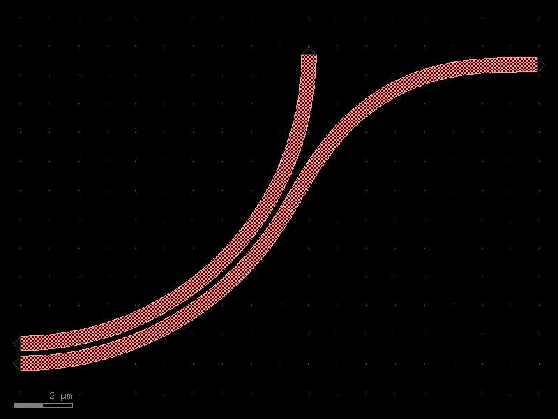
- gdsfactory.components.couplers.coupler_symmetric(bend='bend_s', gap=0.234, dy=4.0, dx=10.0, cross_section='strip', allow_min_radius_violation=False)[source]#
Two coupled straights with bends.
- Parameters:
bend (ComponentSpec) – bend spec.
gap (float) – in um.
dy (float) – port to port vertical spacing.
dx (float) – bend length in x direction.
cross_section (CrossSectionSpec) – section.
allow_min_radius_violation (bool) – if True does not check for min bend radius.
- Return type:
          dx
       |-----|
          ___ o3
         /       |
o2 _____/        |
                 |
o1 _____         |  dy
        \        |
         \___    |
              o4
import gdsfactory as gf

gf.gpdk.PDK.activate()

c = gf.components.coupler_symmetric(bend='bend_s', gap=0.234, dy=4, dx=10, cross_section='strip', allow_min_radius_violation=False).copy()
c.draw_ports()
c.plot()
(Source code, png, hires.png, pdf)

detectors#
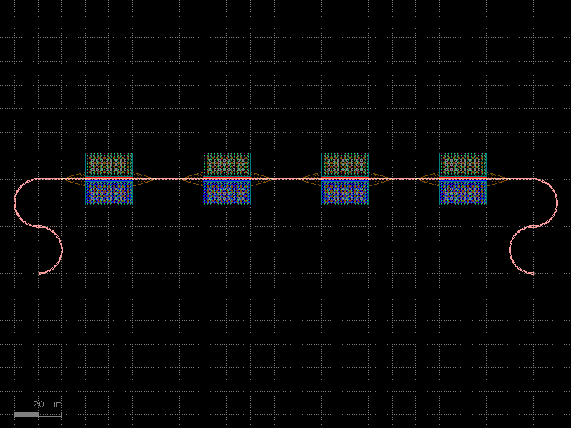
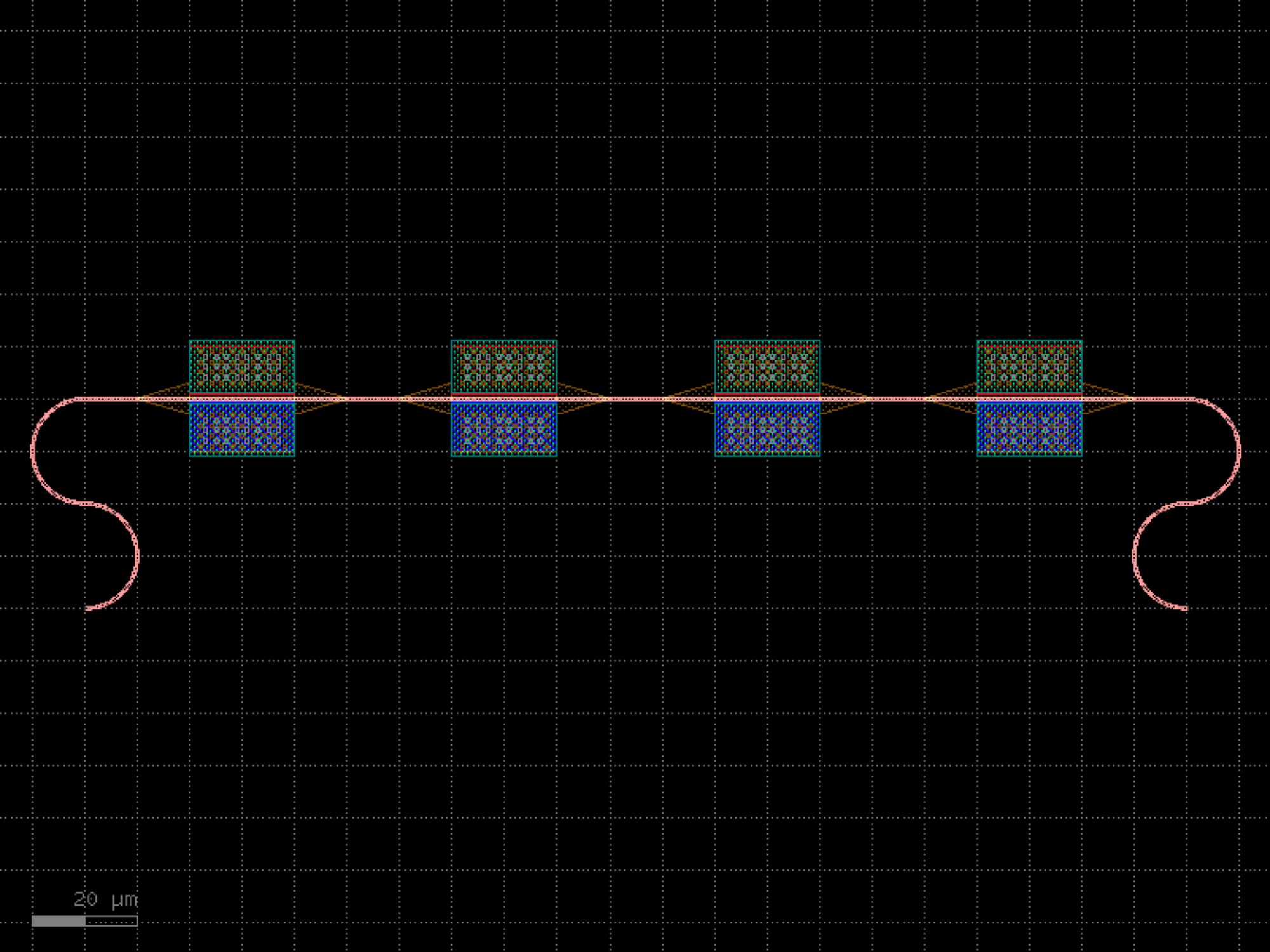
- gdsfactory.components.detectors.ge_detector_straight_si_contacts(length=40.0, cross_section='pn_ge_detector_si_contacts', via_stack='via_stack_slab_m3', via_stack_width=10.0, via_stack_spacing=5.0, via_stack_offset=0.0, taper_length=20.0, taper_width=0.8, taper_cros_section='strip')[source]#
Returns a straight Ge on Si detector with silicon contacts.
There are no contacts on the Ge. These detectors could have lower dark current and sensitivity compared to those with contacts in the Ge. See Chen et al., “High-Responsivity Low-Voltage 28-Gb/s Ge p-i-n Photodetector With Silicon Contacts”, Journal of Lightwave Technology 33(4), 2015.
https://doi.org/10.1109/JLT.2014.2367134
- Parameters:
length (float) – pd length.
cross_section (CrossSectionSpec) – for the waveguide.
via_stack (ComponentSpec) – for the via_stacks. First element
via_stack_width (float) – width of the via_stack.
via_stack_spacing (float) – spacing between via_stacks.
via_stack_offset (float) – with respect to the detector
taper_length (float) – length of the taper.
taper_width (float) – width of the taper.
taper_cros_section (CrossSectionSpec) – cross_section of the taper.
- Return type:
import gdsfactory as gf

gf.gpdk.PDK.activate()

c = gf.components.ge_detector_straight_si_contacts(length=40, cross_section='pn_ge_detector_si_contacts', via_stack='via_stack_slab_m3', via_stack_width=10, via_stack_spacing=5, via_stack_offset=0, taper_length=20, taper_width=0.8, taper_cros_section='strip').copy()
c.draw_ports()
c.plot()
(Source code, png, hires.png, pdf)

dies#
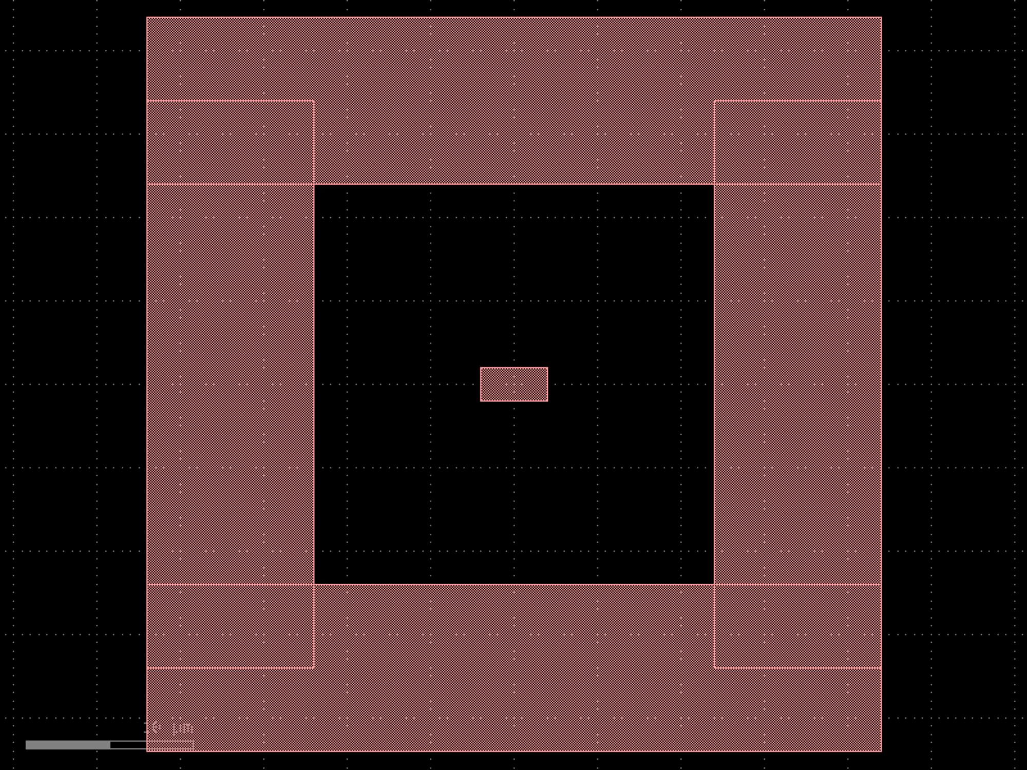
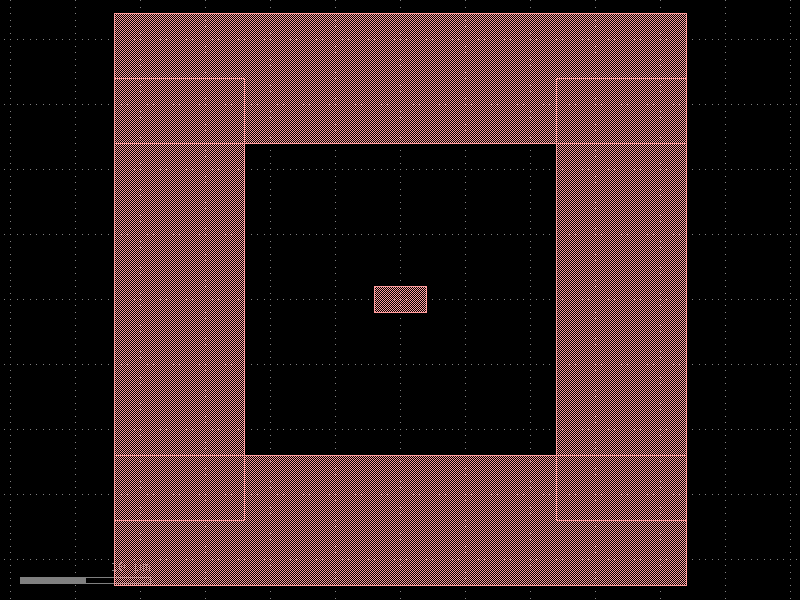
- gdsfactory.components.dies.add_frame(component='rectangle', width=10.0, spacing=10.0, layer='WG')[source]#
Returns component with a frame around it.
- Parameters:
component (ComponentSpec) – Component to frame.
width (float) – of the frame.
spacing (float) – of component to frame.
layer (LayerSpec) – frame layer.
- Return type:
import gdsfactory as gf

gf.gpdk.PDK.activate()

c = gf.components.add_frame(component='rectangle', width=10, spacing=10, layer='WG').copy()
c.draw_ports()
c.plot()
(Source code, png, hires.png, pdf)

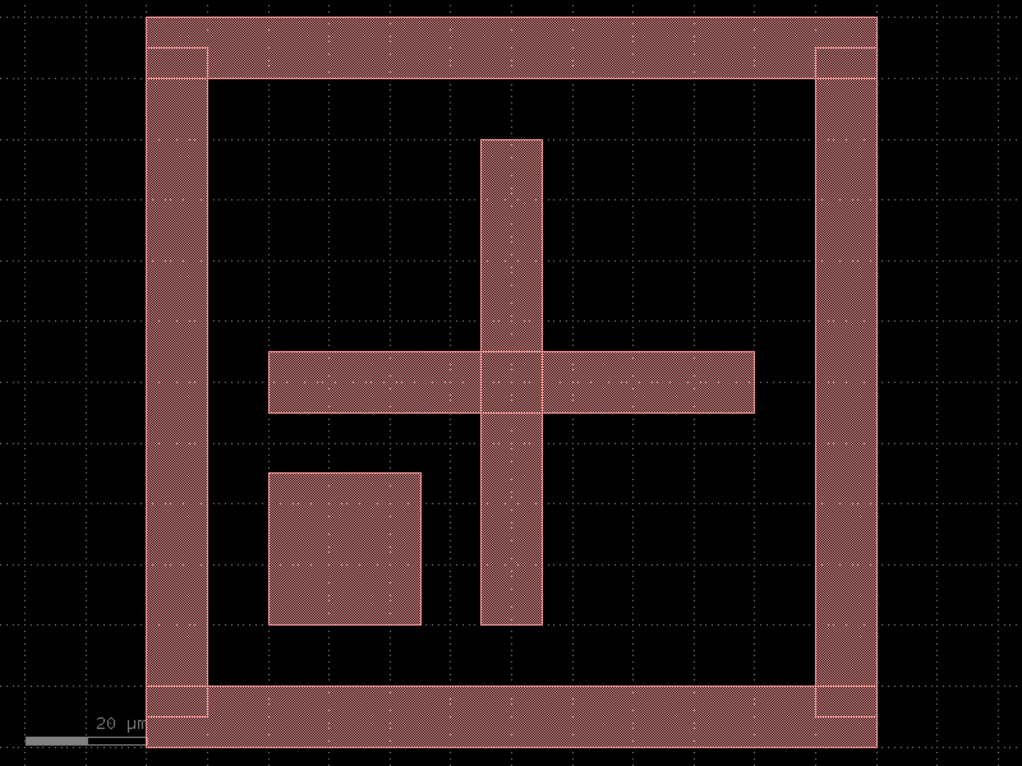
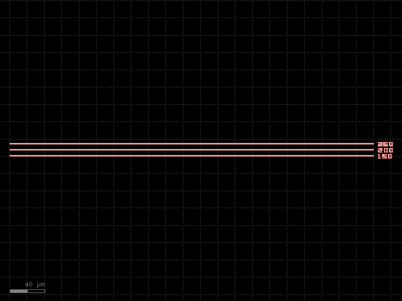
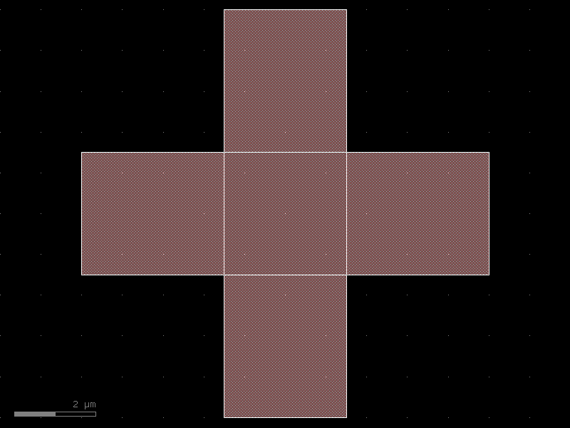
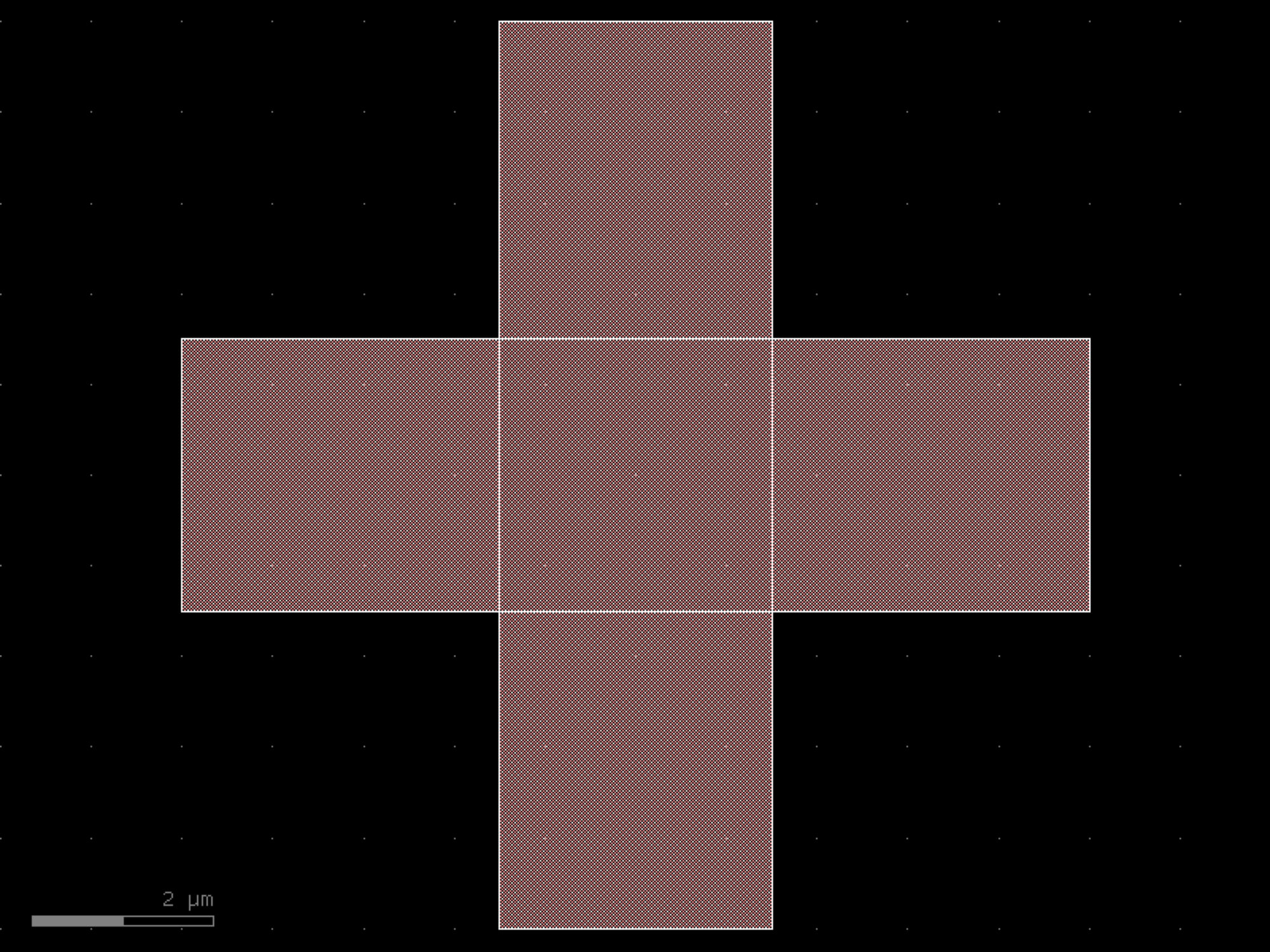
- gdsfactory.components.dies.align_wafer(width=10.0, spacing=10.0, cross_length=80.0, layer='WG', layer_cladding=None, square_corner='bottom_left')[source]#
Returns cross inside a frame to align wafer.
- Parameters:
width (float) – in um.
spacing (float) – in um.
cross_length (float) – for the cross.
layer (LayerSpec) – for the cross.
layer_cladding (tuple[int, int] | None) – optional.
square_corner (str) – bottom_left, bottom_right, top_right, top_left.
- Return type:
import gdsfactory as gf

gf.gpdk.PDK.activate()

c = gf.components.align_wafer(width=10, spacing=10, cross_length=80, layer='WG', square_corner='bottom_left').copy()
c.draw_ports()
c.plot()
(Source code, png, hires.png, pdf)

- gdsfactory.components.dies.die(size=(10000.0, 10000.0), street_width=100.0, street_length=1000.0, die_name='chip99', text_size=100.0, text_location='SW', layer='FLOORPLAN', bbox_layer='FLOORPLAN', text_layer='WG', text='text', draw_corners=False)[source]#
Returns die with optional markers marking the boundary of the die.
- Parameters:
size (Size) – x, y dimensions of the die.
street_width (float) – Width of the corner marks for die-sawing.
street_length (float) – Length of the corner marks for die-sawing.
die_name (str | None) – Label text. If None, no label is added.
text_size (float) – Label text size.
text_location (str | Float2) – {‘NW’, ‘N’, ‘NE’, ‘SW’, ‘S’, ‘SE’} or (x, y) coordinate.
layer (LayerSpec | None) – For street widths. None to not draw the street widths.
bbox_layer (LayerSpec | None) – optional bbox layer drawn bounding box around the die.
text_layer (LayerSpec) – Layer for the die name text.
text (ComponentSpec) – function use for generating text. Needs to accept text, size, layer.
draw_corners (bool) – True draws only corners. False draws a square die.
- Return type:
gf.Component
import gdsfactory as gf

gf.gpdk.PDK.activate()

c = gf.components.die(size=(10000, 10000), street_width=100, street_length=1000, die_name='chip99', text_size=100, text_location='SW', layer='FLOORPLAN', bbox_layer='FLOORPLAN', text_layer='WG', text='text', draw_corners=False).copy()
c.draw_ports()
c.plot()
(Source code, png, hires.png, pdf)

- gdsfactory.components.dies.die_frame(size=(11200.0, 5000.0), layer_floorplan='FLOORPLAN')[source]#
- Parameters:
size (tuple[float, float])
layer_floorplan (tuple[int, int] | str | int | LayerEnum)
- Return type:
import gdsfactory as gf

gf.gpdk.PDK.activate()

c = gf.components.die_frame(size=(11200, 5000), layer_floorplan='FLOORPLAN').copy()
c.draw_ports()
c.plot()
(Source code, png, hires.png, pdf)
- gdsfactory.components.dies.die_frame_phix(die_frame='die_frame', nfibers=32, npads=60, npads_rf=6, fiber_pitch=127.0, pad_pitch=150.0, pad_pitch_gsg=720.0, edge_coupler='edge_coupler_silicon', grating_coupler=None, cross_section='strip', pad='pad', pad_gsg='pad_gsg', edge_to_pad_distance=200.0, edge_to_pad_distance_left=None, pad_port_name_top='e4', pad_port_name_bot='e2', pad_port_name_rf='e2', layer_fiducial='M3', layer_ruler='WG', ruler_bbox_layers=None, ruler_bbox_offset=3.0, ruler_yoffset=0, ruler_xoffset=0, fiber_coupler_xoffset=0, with_right_fiber_coupler=True, with_left_fiber_coupler=True, text_offset=(20, 10), text='text_rectangular', pad_side_distance=1160.0, xoffset_rf_pads=50, pad_rotation_dc_north=0, pad_rotation_dc_south=0, pad_rotation_rf=0, with_loopback=True)[source]#
A die_frame with grating couplers and pads.
- Parameters:
die_frame (str | Callable[[...], Component] | dict[str, Any] | DKCell | partial[Component]) – die_frame spec.
nfibers (int) – the number of grating couplers.
npads (int) – the number of pads.
npads_rf (int) – the number of RF pads on the left side.
fiber_pitch (float) – the pitch of the grating couplers, in um.
pad_pitch (float) – the pitch of the pads, in um.
pad_pitch_gsg (float) – the pitch of the GSG pads, in um.
edge_coupler (str | Callable[[...], Component] | dict[str, Any] | DKCell | partial[Component] | None) – the grating coupler component.
grating_coupler (str | Callable[[...], Component] | dict[str, Any] | DKCell | partial[Component] | None) – Optional grating coupler.
cross_section (CrossSection | str | dict[str, Any] | Callable[[...], CrossSection] | SymmetricalCrossSection | DCrossSection) – the cross section.
pad (str | Callable[[...], Component] | dict[str, Any] | DKCell | partial[Component]) – the pad component.
pad_gsg (str | Callable[[...], Component] | dict[str, Any] | DKCell | partial[Component]) – the GSG pad component.
edge_to_pad_distance (float) – the distance from the edge to the pads, in um.
edge_to_pad_distance_left (float | None) – Optional distance from the left edge to the pads, in um. If None, uses edge_to_pad_distance for both sides.
pad_port_name_top (str) – name of the pad port name at the top facing south.
pad_port_name_bot (str) – name of the pad port name at the bottom facing north.
pad_port_name_rf (str) – name of the RF pad port name.
layer_fiducial (tuple[int, int] | str | int | LayerEnum) – layer for fiducials.
layer_ruler (tuple[int, int] | str | int | LayerEnum) – layer for ruler.
ruler_bbox_layers (tuple[tuple[int, int] | str | int | LayerEnum, ...] | None) – layers for bbox.
ruler_bbox_offset (float) – offset for bbox.
ruler_yoffset (float) – y-offset for ruler.
ruler_xoffset (float) – x-offset for ruler.
fiber_coupler_xoffset (float) – x-offset for fiber couplers.
with_right_fiber_coupler (bool) – if True, adds edge couplers on the right side.
with_left_fiber_coupler (bool) – if True, adds edge couplers on the left side.
text_offset (tuple[float, float]) – offset for text.
text (str | Callable[[...], Component] | dict[str, Any] | DKCell | partial[Component] | None) – text component spec.
pad_side_distance (float) – distance from the die frame side to the first pad, in um.
xoffset_rf_pads (float) – RF pads x-offset.
pad_rotation_dc_north (float) – rotation for DC pads.
pad_rotation_dc_south (float) – rotation for DC pads.
pad_rotation_rf (float) – rotation for RF pads.
with_loopback (bool) – if True, adds loopback structures.
- Return type:
import gdsfactory as gf

gf.gpdk.PDK.activate()

c = gf.components.die_frame_phix(die_frame='die_frame', nfibers=32, npads=60, npads_rf=6, fiber_pitch=127, pad_pitch=150, pad_pitch_gsg=720, edge_coupler='edge_coupler_silicon', cross_section='strip', pad='pad', pad_gsg='pad_gsg', edge_to_pad_distance=200, pad_port_name_top='e4', pad_port_name_bot='e2', pad_port_name_rf='e2', layer_fiducial='M3', layer_ruler='WG', ruler_bbox_offset=3, ruler_yoffset=0, ruler_xoffset=0, fiber_coupler_xoffset=0, with_right_fiber_coupler=True, with_left_fiber_coupler=True, text_offset=(20, 10), text='text_rectangular', pad_side_distance=1160, xoffset_rf_pads=50, pad_rotation_dc_north=0, pad_rotation_dc_south=0, pad_rotation_rf=0, with_loopback=True).copy()
c.draw_ports()
c.plot()
(Source code, png, hires.png, pdf)

- gdsfactory.components.dies.die_frame_phix_dc(die_frame='die_frame', nfibers=32, npads=59, npads_rf=6, fiber_pitch=127.0, pad_pitch=150.0, pad_pitch_gsg=720.0, edge_coupler='edge_coupler_silicon', grating_coupler=None, cross_section='strip', pad='pad', pad_gsg='pad_gsg', edge_to_pad_distance=200.0, pad_port_name_top='e4', pad_port_name_bot='e2', layer_fiducial='M3', layer_ruler='WG', ruler_bbox_layers=None, ruler_bbox_offset=3.0, ruler_yoffset=0, ruler_xoffset=0, with_right_fiber_coupler=True, with_left_fiber_coupler=True, fiber_coupler_xoffset=0, text_offset=(20, 10), text=None, pad_rotation_dc_north=0, pad_rotation_dc_south=0, pad_side_distance=1160.0)[source]#
- Parameters:
die_frame (str | Callable[[...], Component] | dict[str, Any] | DKCell | partial[Component])
nfibers (int)
npads (int)
npads_rf (int)
fiber_pitch (float)
pad_pitch (float)
pad_pitch_gsg (float)
edge_coupler (str | Callable[[...], Component] | dict[str, Any] | DKCell | partial[Component] | None)
grating_coupler (str | Callable[[...], Component] | dict[str, Any] | DKCell | partial[Component] | None)
cross_section (CrossSection | str | dict[str, Any] | Callable[[...], CrossSection] | SymmetricalCrossSection | DCrossSection)
pad (str | Callable[[...], Component] | dict[str, Any] | DKCell | partial[Component])
pad_gsg (str | Callable[[...], Component] | dict[str, Any] | DKCell | partial[Component])
edge_to_pad_distance (float)
pad_port_name_top (str)
pad_port_name_bot (str)
layer_fiducial (tuple[int, int] | str | int | LayerEnum)
layer_ruler (tuple[int, int] | str | int | LayerEnum)
ruler_bbox_layers (tuple[tuple[int, int] | str | int | LayerEnum, ...] | None)
ruler_bbox_offset (float)
ruler_yoffset (float)
ruler_xoffset (float)
with_right_fiber_coupler (bool)
with_left_fiber_coupler (bool)
fiber_coupler_xoffset (float)
text_offset (tuple[float, float])
text (str | Callable[[...], Component] | dict[str, Any] | DKCell | partial[Component] | None)
pad_rotation_dc_north (float)
pad_rotation_dc_south (float)
pad_side_distance (float)
- Return type:
import gdsfactory as gf

gf.gpdk.PDK.activate()

c = gf.components.die_frame_phix_dc(die_frame='die_frame', nfibers=32, npads=59, npads_rf=6, fiber_pitch=127, pad_pitch=150, pad_pitch_gsg=720, edge_coupler='edge_coupler_silicon', cross_section='strip', pad='pad', pad_gsg='pad_gsg', edge_to_pad_distance=200, pad_port_name_top='e4', pad_port_name_bot='e2', layer_fiducial='M3', layer_ruler='WG', ruler_bbox_offset=3, ruler_yoffset=0, ruler_xoffset=0, with_right_fiber_coupler=True, with_left_fiber_coupler=True, fiber_coupler_xoffset=0, text_offset=(20, 10), pad_rotation_dc_north=0, pad_rotation_dc_south=0, pad_side_distance=1160).copy()
c.draw_ports()
c.plot()
(Source code, png, hires.png, pdf)

- gdsfactory.components.dies.die_frame_phix_rf(die_frame='die_frame_rf', nfibers=32, npads=59, npads_rf=6, fiber_pitch=127.0, pad_pitch=150.0, pad_pitch_gsg=720.0, edge_coupler='edge_coupler_silicon', grating_coupler=None, cross_section='strip', pad='pad', pad_gsg='pad_gsg', edge_to_pad_distance=200.0, pad_port_name_top='e4', pad_port_name_bot='e2', pad_port_name_rf='e2', layer_fiducial='M3', layer_ruler='WG', ruler_bbox_layers=None, ruler_bbox_offset=3.0, ruler_yoffset=0, ruler_xoffset=0, with_right_fiber_coupler=True, with_left_fiber_coupler=False, fiber_coupler_xoffset=0, text_offset=(20, 10), text=None, pad_side_distance=350.0, xoffset_rf_pads=50, pad_rotation_rf=0, pad_rotation_dc_north=0, pad_rotation_dc_south=0)[source]#
- Parameters:
die_frame (str | Callable[[...], Component] | dict[str, Any] | DKCell | partial[Component])
nfibers (int)
npads (int)
npads_rf (int)
fiber_pitch (float)
pad_pitch (float)
pad_pitch_gsg (float)
edge_coupler (str | Callable[[...], Component] | dict[str, Any] | DKCell | partial[Component] | None)
grating_coupler (str | Callable[[...], Component] | dict[str, Any] | DKCell | partial[Component] | None)
cross_section (CrossSection | str | dict[str, Any] | Callable[[...], CrossSection] | SymmetricalCrossSection | DCrossSection)
pad (str | Callable[[...], Component] | dict[str, Any] | DKCell | partial[Component])
pad_gsg (str | Callable[[...], Component] | dict[str, Any] | DKCell | partial[Component])
edge_to_pad_distance (float)
pad_port_name_top (str)
pad_port_name_bot (str)
pad_port_name_rf (str)
layer_fiducial (tuple[int, int] | str | int | LayerEnum)
layer_ruler (tuple[int, int] | str | int | LayerEnum)
ruler_bbox_layers (tuple[tuple[int, int] | str | int | LayerEnum, ...] | None)
ruler_bbox_offset (float)
ruler_yoffset (float)
ruler_xoffset (float)
with_right_fiber_coupler (bool)
with_left_fiber_coupler (bool)
fiber_coupler_xoffset (float)
text_offset (tuple[float, float])
text (str | Callable[[...], Component] | dict[str, Any] | DKCell | partial[Component] | None)
pad_side_distance (float)
xoffset_rf_pads (float)
pad_rotation_rf (float)
pad_rotation_dc_north (float)
pad_rotation_dc_south (float)
- Return type:
import gdsfactory as gf

gf.gpdk.PDK.activate()

c = gf.components.die_frame_phix_rf(die_frame='die_frame_rf', nfibers=32, npads=59, npads_rf=6, fiber_pitch=127, pad_pitch=150, pad_pitch_gsg=720, edge_coupler='edge_coupler_silicon', cross_section='strip', pad='pad', pad_gsg='pad_gsg', edge_to_pad_distance=200, pad_port_name_top='e4', pad_port_name_bot='e2', pad_port_name_rf='e2', layer_fiducial='M3', layer_ruler='WG', ruler_bbox_offset=3, ruler_yoffset=0, ruler_xoffset=0, with_right_fiber_coupler=True, with_left_fiber_coupler=False, fiber_coupler_xoffset=0, text_offset=(20, 10), pad_side_distance=350, xoffset_rf_pads=50, pad_rotation_rf=0, pad_rotation_dc_north=0, pad_rotation_dc_south=0).copy()
c.draw_ports()
c.plot()
(Source code, png, hires.png, pdf)
- gdsfactory.components.dies.die_frame_rf(size=(10400.0, 5000.0), layer_floorplan='FLOORPLAN')[source]#
- Parameters:
size (tuple[float, float])
layer_floorplan (tuple[int, int] | str | int | LayerEnum)
- Return type:
import gdsfactory as gf

gf.gpdk.PDK.activate()

c = gf.components.die_frame_rf(size=(10400, 5000), layer_floorplan='FLOORPLAN').copy()
c.draw_ports()
c.plot()
(Source code, png, hires.png, pdf)

- gdsfactory.components.dies.die_frame_with_pads(die_frame='die_frame', ngratings=14, npads=31, grating_pitch=250.0, pad_pitch=300.0, grating_coupler='grating_coupler_te', cross_section='strip', pad='pad', edge_to_pad_distance=150.0, edge_to_grating_distance=150.0, with_loopback=True, loopback_radius=None, pad_port_name_top='e4', pad_port_name_bot='e2')[source]#
A die_frame with grating couplers and pads.
- Parameters:
die_frame (str | Callable[[...], Component] | dict[str, Any] | DKCell | partial[Component]) – die_frame spec.
ngratings (int) – the number of grating couplers.
npads (int) – the number of pads.
grating_pitch (float) – the pitch of the grating couplers, in um.
pad_pitch (float) – the pitch of the pads, in um.
grating_coupler (str | Callable[[...], Component] | dict[str, Any] | DKCell | partial[Component] | None) – the grating coupler component.
cross_section (CrossSection | str | dict[str, Any] | Callable[[...], CrossSection] | SymmetricalCrossSection | DCrossSection) – the cross section.
pad (str | Callable[[...], Component] | dict[str, Any] | DKCell | partial[Component]) – the pad component.
edge_to_pad_distance (float) – the distance from the edge to the pads, in um.
edge_to_grating_distance (float) – the distance from the edge to the grating couplers, in um.
with_loopback (bool) – if True, adds a loopback between edge GCs. Only works for rotation = 90 for now.
loopback_radius (float | None) – optional radius for loopback.
pad_port_name_top (str) – name of the pad port name at the btop facing south.
pad_port_name_bot (str) – name of the pad port name at the bottom facing north.
- Return type:
import gdsfactory as gf

gf.gpdk.PDK.activate()

c = gf.components.die_frame_with_pads(die_frame='die_frame', ngratings=14, npads=31, grating_pitch=250, pad_pitch=300, grating_coupler='grating_coupler_te', cross_section='strip', pad='pad', edge_to_pad_distance=150, edge_to_grating_distance=150, with_loopback=True, pad_port_name_top='e4', pad_port_name_bot='e2').copy()
c.draw_ports()
c.plot()
(Source code, png, hires.png, pdf)

- gdsfactory.components.dies.die_with_pads(size=(11470.0, 4900.0), ngratings=14, npads=31, grating_pitch=250.0, pad_pitch=300.0, grating_coupler='grating_coupler_te', cross_section='strip', pad='pad', layer_floorplan='FLOORPLAN', edge_to_pad_distance=150.0, edge_to_grating_distance=150.0, with_loopback=True, loopback_radius=None, pad_port_name_top='e4', pad_port_name_bot='e2')[source]#
A die with grating couplers and pads.
- Parameters:
size (tuple[float, float]) – the size of the die, in um.
ngratings (int) – the number of grating couplers.
npads (int) – the number of pads.
grating_pitch (float) – the pitch of the grating couplers, in um.
pad_pitch (float) – the pitch of the pads, in um.
grating_coupler (str | Callable[[...], Component] | dict[str, Any] | DKCell | partial[Component] | None) – the grating coupler component.
cross_section (CrossSection | str | dict[str, Any] | Callable[[...], CrossSection] | SymmetricalCrossSection | DCrossSection) – the cross section.
pad (str | Callable[[...], Component] | dict[str, Any] | DKCell | partial[Component]) – the pad component.
layer_floorplan (tuple[int, int] | str | int | LayerEnum) – the layer of the floorplan.
edge_to_pad_distance (float) – the distance from the edge to the pads, in um.
edge_to_grating_distance (float) – the distance from the edge to the grating couplers, in um.
with_loopback (bool) – if True, adds a loopback between edge GCs. Only works for rotation = 90 for now.
loopback_radius (float | None) – optional radius for loopback.
pad_port_name_top (str) – name of the pad port name at the btop facing south.
pad_port_name_bot (str) – name of the pad port name at the bottom facing north.
- Return type:
import gdsfactory as gf

gf.gpdk.PDK.activate()

c = gf.components.die_with_pads(size=(11470, 4900), ngratings=14, npads=31, grating_pitch=250, pad_pitch=300, grating_coupler='grating_coupler_te', cross_section='strip', pad='pad', layer_floorplan='FLOORPLAN', edge_to_pad_distance=150, edge_to_grating_distance=150, with_loopback=True, pad_port_name_top='e4', pad_port_name_bot='e2').copy()
c.draw_ports()
c.plot()
(Source code, png, hires.png, pdf)
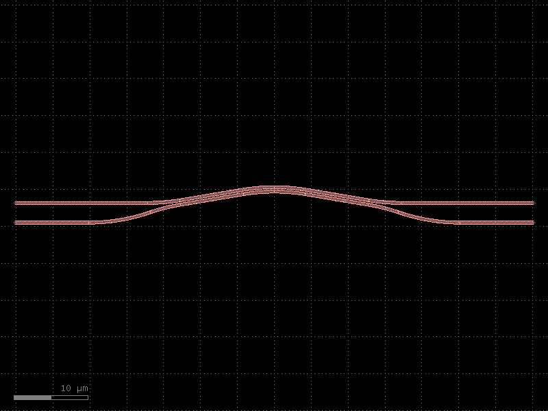
- gdsfactory.components.dies.seal_ring(size=(500, 500), seal='via_stack', width=10, padding=10.0, with_north=True, with_south=True, with_east=True, with_west=True)[source]#
Returns a continuous seal ring boundary at the chip/die.
Prevents cracks from spreading and shields when connected to ground.
- Parameters:
size (tuple[float, float]) – of the seal.
seal (ComponentSpec) – function for the seal.
width (float) – of the seal.
padding (float) – from component to seal.
with_north (bool) – includes seal.
with_south (bool) – includes seal.
with_east (bool) – includes seal.
with_west (bool) – includes seal.
- Return type:
import gdsfactory as gf

gf.gpdk.PDK.activate()

c = gf.components.seal_ring(size=(500, 500), seal='via_stack', width=10, padding=10, with_north=True, with_south=True, with_east=True, with_west=True).copy()
c.draw_ports()
c.plot()
(Source code, png, hires.png, pdf)
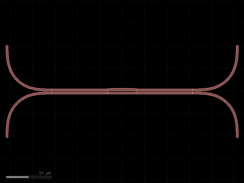
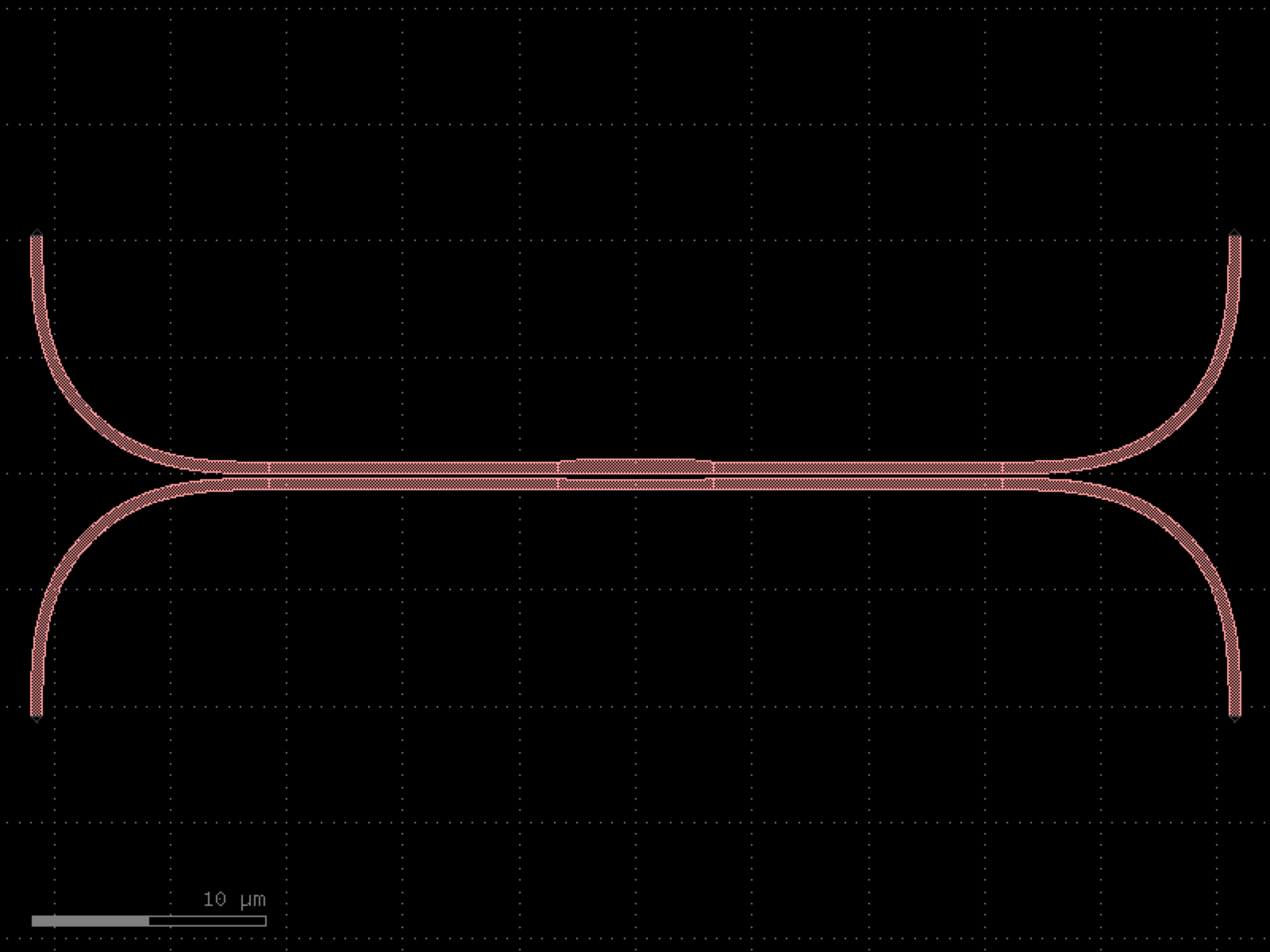

- gdsfactory.components.dies.seal_ring_segmented(size=(500, 500), length_segment=10, width_segment=3, spacing_segment=2, corner='via_stack_corner45_extended', via_stack='via_stack_m1_mtop', with_north=True, with_south=True, with_east=True, with_west=True)[source]#
Segmented Seal ring.
- Parameters:
size (tuple[float, float]) – of the seal ring.
length_segment (float) – length of each segment.
width_segment (float) – width of each segment.
spacing_segment (float) – spacing between segments.
corner (ComponentSpec) – corner component.
via_stack (ComponentSpec) – via_stack component.
with_north (bool) – includes seal.
with_south (bool) – includes seal.
with_east (bool) – includes seal.
with_west (bool) – includes seal.
- Return type:
import gdsfactory as gf

gf.gpdk.PDK.activate()

c = gf.components.seal_ring_segmented(size=(500, 500), length_segment=10, width_segment=3, spacing_segment=2, corner='via_stack_corner45_extended', via_stack='via_stack_m1_mtop', with_north=True, with_south=True, with_east=True, with_west=True).copy()
c.draw_ports()
c.plot()
(Source code, png, hires.png, pdf)
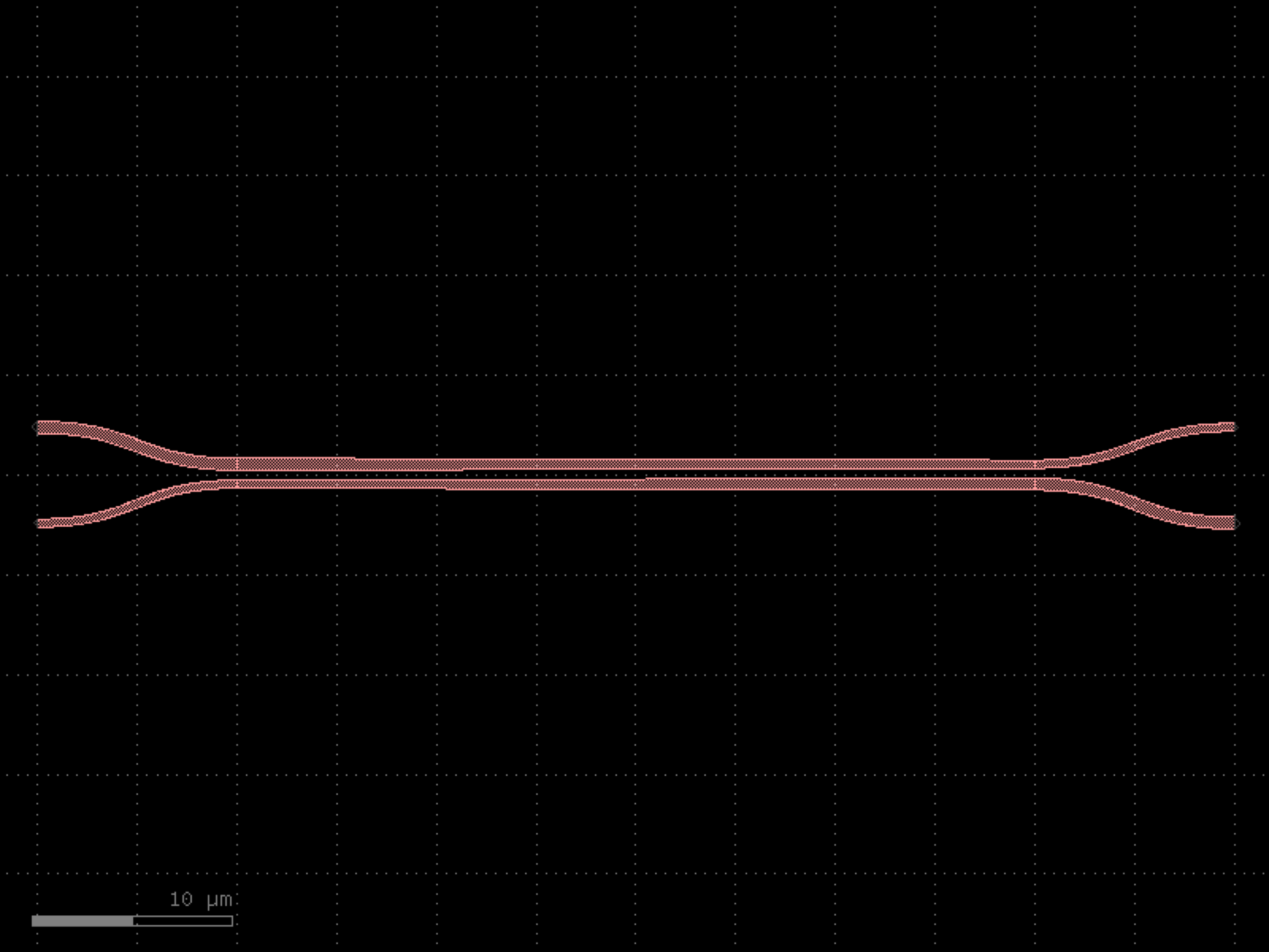
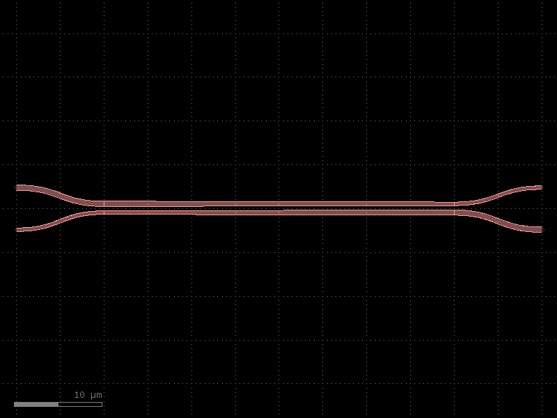
- gdsfactory.components.dies.wafer(reticle='die', cols=(2, 6, 6, 8, 8, 6, 6, 2), xspacing=None, yspacing=None, die_name_col_row=False)[source]#
Returns complete wafer. Useful for mask aligner steps.
- Parameters:
reticle (ComponentSpec) – spec for each wafer reticle.
cols (tuple[int, ...]) – how many columns per row.
xspacing (float | None) – optional spacing, defaults to reticle.xsize.
yspacing (float | None) – optional spacing, defaults to reticle.ysize.
die_name_col_row (bool) – if True, die name is row_col, otherwise is a number
- Return type:
import gdsfactory as gf

gf.gpdk.PDK.activate()

c = gf.components.wafer(reticle='die', cols=(2, 6, 6, 8, 8, 6, 6, 2), die_name_col_row=False).copy()
c.draw_ports()
c.plot()
(Source code, png, hires.png, pdf)
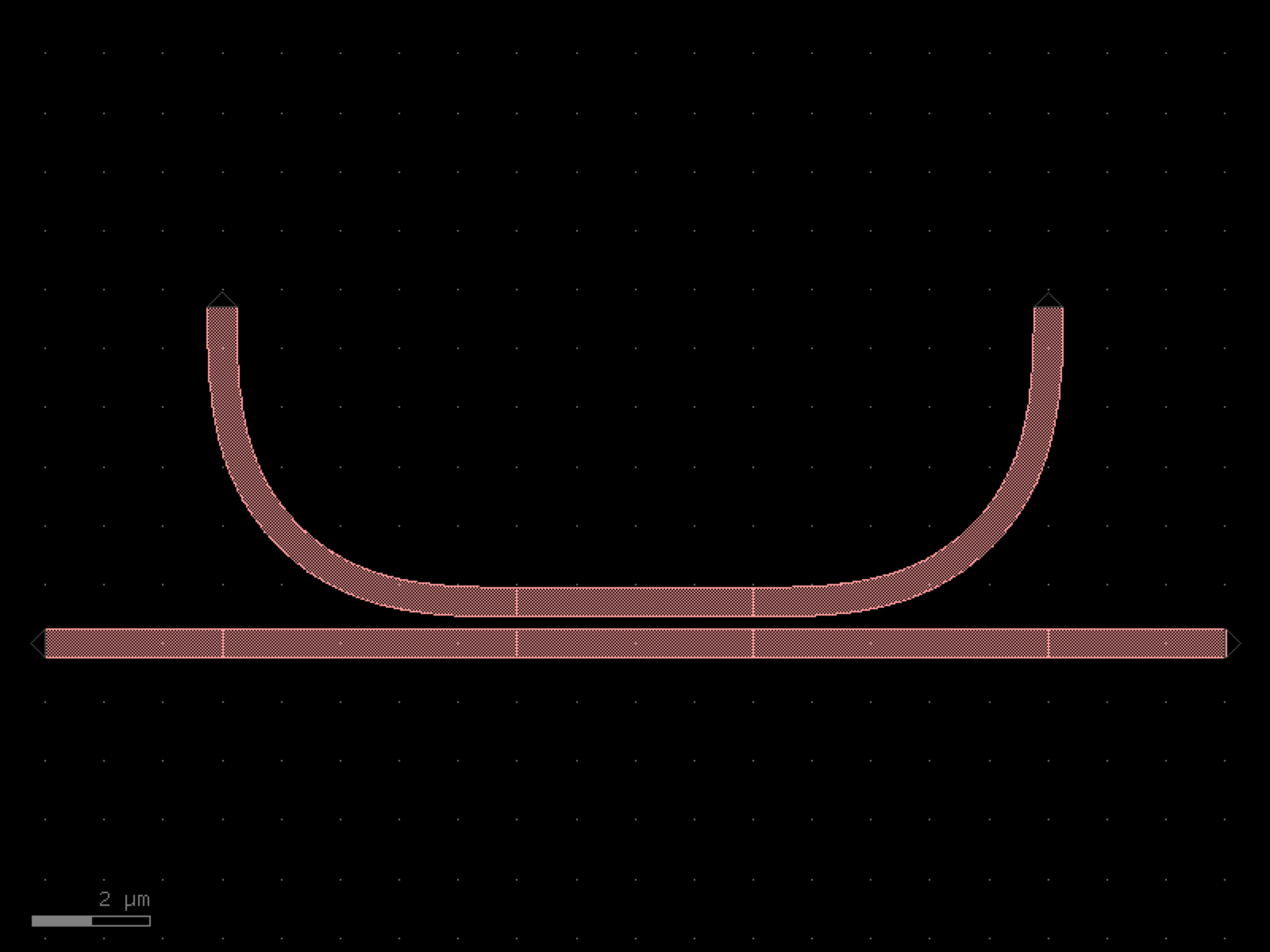

edge_couplers#
- gdsfactory.components.edge_couplers.edge_coupler_array(edge_coupler='edge_coupler_silicon', n=5, pitch=127.0, x_reflection=False, text='text_rectangular', text_offset=(10, 20), text_rotation=0)[source]#
Fiber array edge coupler based on an inverse taper.
Each edge coupler adds a ruler for polishing.
- Parameters:
edge_coupler (ComponentSpec) – edge coupler spec.
n (int) – number of channels.
pitch (float) – Fiber pitch.
x_reflection (bool) – horizontal mirror.
text (ComponentSpec | None) – text spec.
text_offset (Float2) – from edge coupler.
text_rotation (float) – text rotation in degrees.
- Return type:
import gdsfactory as gf

gf.gpdk.PDK.activate()

c = gf.components.edge_coupler_array(edge_coupler='edge_coupler_silicon', n=5, pitch=127, x_reflection=False, text='text_rectangular', text_offset=(10, 20), text_rotation=0).copy()
c.draw_ports()
c.plot()
(Source code, png, hires.png, pdf)
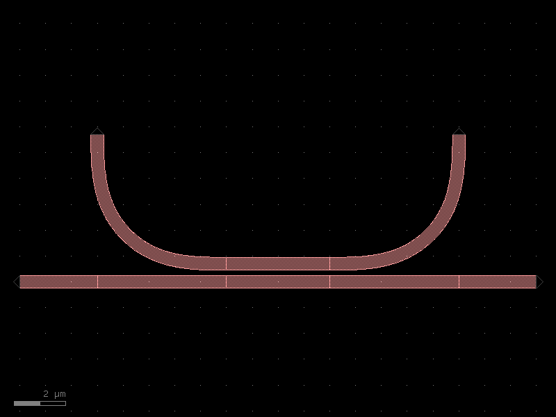
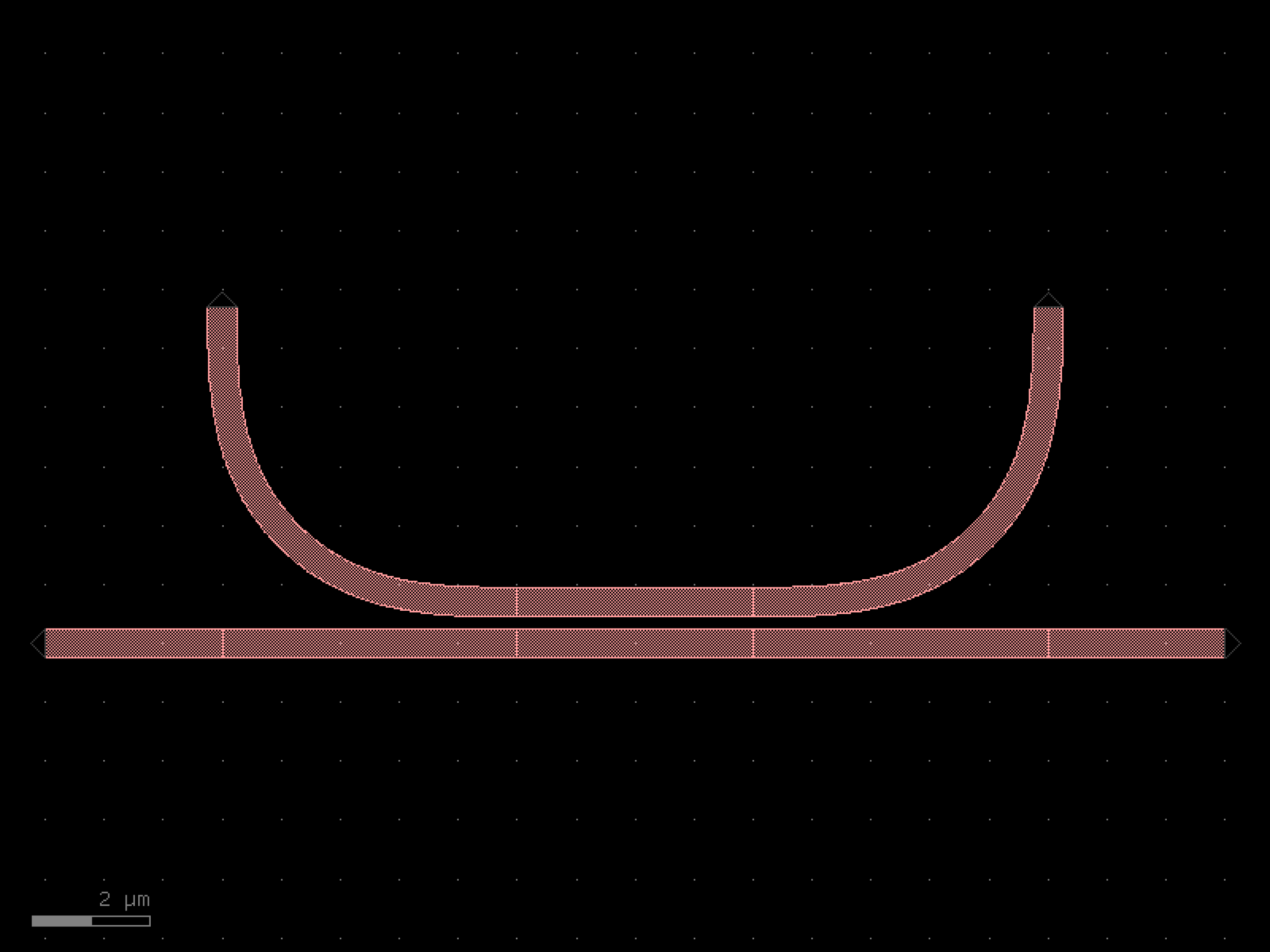

- gdsfactory.components.edge_couplers.edge_coupler_array_with_loopback(edge_coupler='edge_coupler_silicon', cross_section='strip', radius=None, n=8, pitch=127.0, x_reflection=False, text='text_rectangular', text_offset=(0, 10), text_rotation=0)[source]#
Fiber array edge coupler.
- Parameters:
edge_coupler (ComponentSpec) – edge coupler.
cross_section (CrossSectionSpec) – spec.
radius (float | None) – bend radius loopback (um).
n (int) – number of channels.
pitch (float) – Fiber pitch (um).
x_reflection (bool) – horizontal mirror.
text (ComponentSpec | None) – Optional text spec.
text_offset (Float2) – x, y.
text_rotation (float) – text rotation in degrees.
- Return type:
import gdsfactory as gf

gf.gpdk.PDK.activate()

c = gf.components.edge_coupler_array_with_loopback(edge_coupler='edge_coupler_silicon', cross_section='strip', n=8, pitch=127, x_reflection=False, text='text_rectangular', text_offset=(0, 10), text_rotation=0).copy()
c.draw_ports()
c.plot()
(Source code, png, hires.png, pdf)
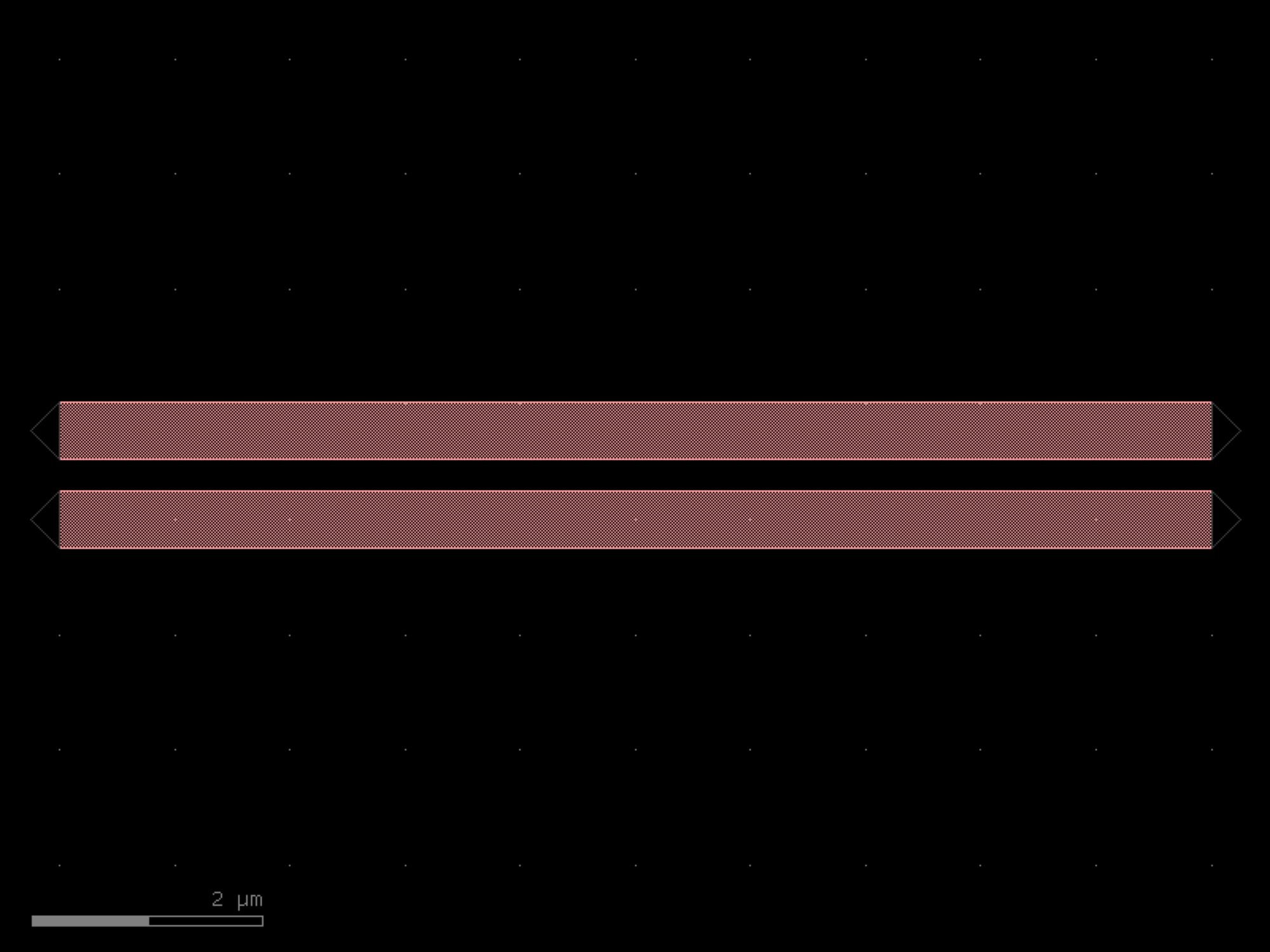

- gdsfactory.components.edge_couplers.edge_coupler_silicon(length=100, width1=0.5, width2=0.2, with_two_ports=True, port_names=('o1', 'o2'), port_types=('optical', 'edge_coupler'), cross_section='strip')[source]#
Edge coupler for silicon photonics.
- Parameters:
length (float) – length of the taper.
width1 (float) – width1 of the taper.
width2 (float) – width2 of the taper.
with_two_ports (bool) – add two ports.
port_names (tuple[str, str]) – tuple with port names.
port_types (tuple[str, str]) – tuple with port types.
cross_section (CrossSectionSpec) – cross_section spec.
- Return type:
import gdsfactory as gf

gf.gpdk.PDK.activate()

c = gf.components.edge_coupler_silicon(length=100, width1=0.5, width2=0.2, with_two_ports=True, port_names=('o1', 'o2'), port_types=('optical', 'edge_coupler'), cross_section='strip').copy()
c.draw_ports()
c.plot()
(Source code, png, hires.png, pdf)
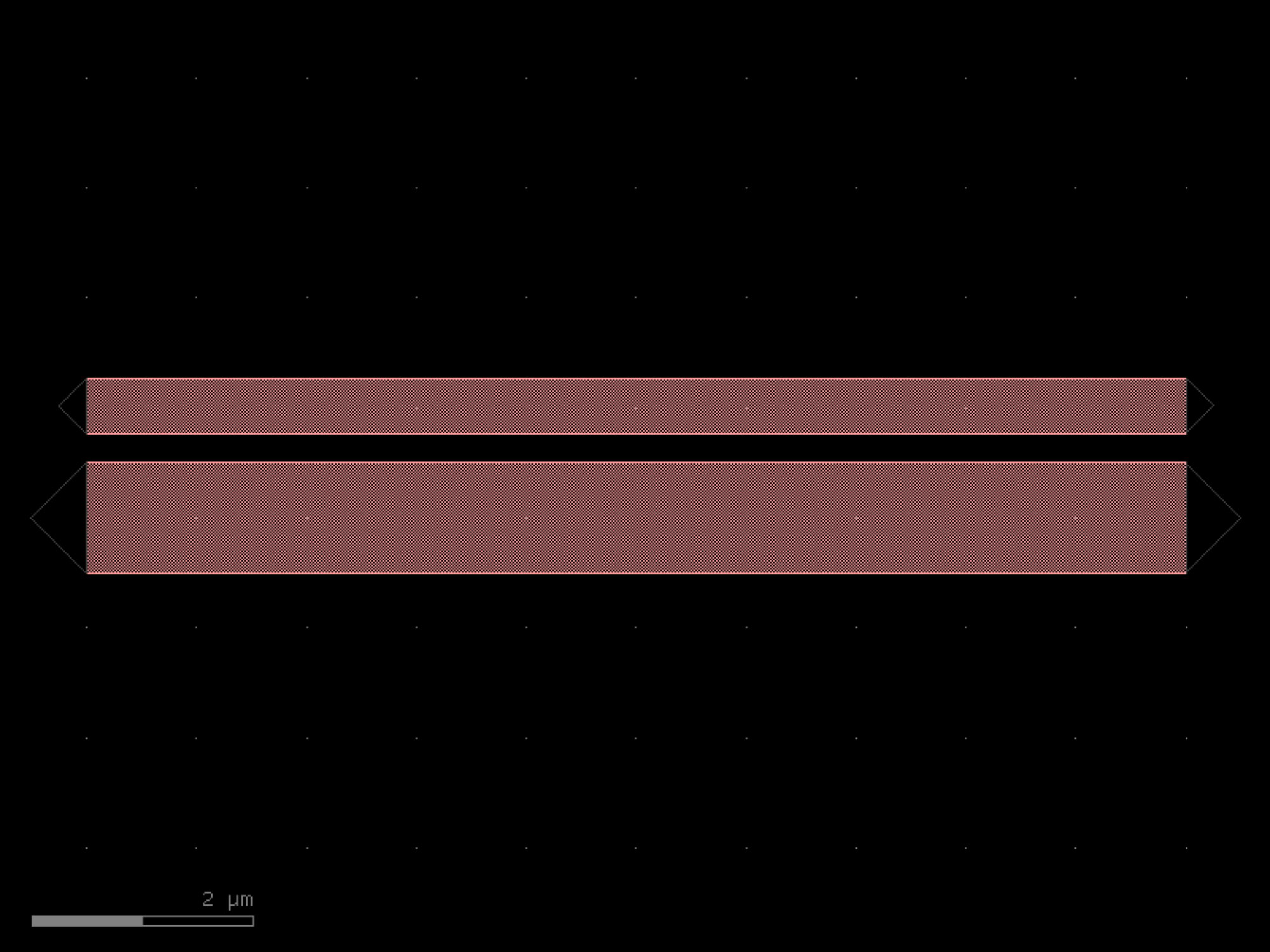
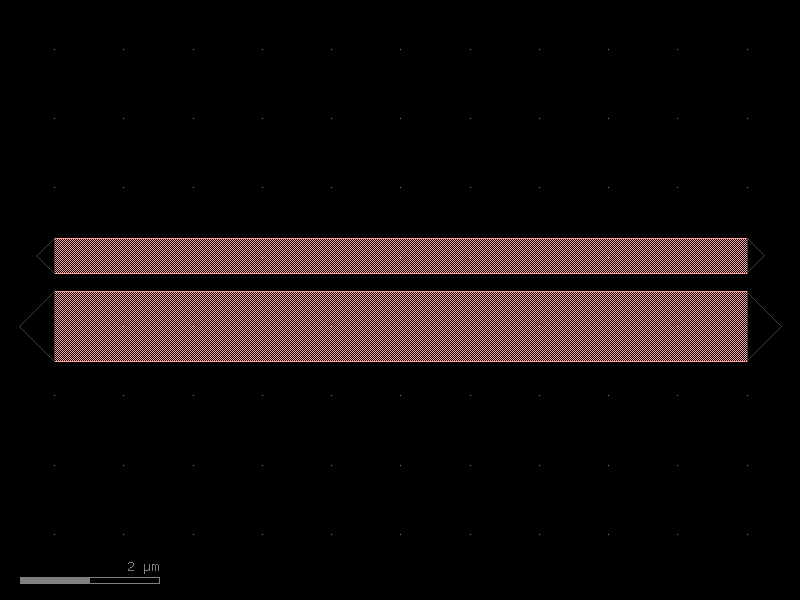
filters#
- gdsfactory.components.filters.awg(arms=10, outputs=3, free_propagation_region_input_function=functools.partial(<function free_propagation_region>, inputs=1), free_propagation_region_output_function=functools.partial(<function free_propagation_region>, inputs=10, width1=10, width2=20.0), fpr_spacing=50.0, arm_spacing=1.0, length_increment=0.0, cross_section='strip')[source]#
Returns an Arrayed Waveguide grating.
To simulate you can use dnrobin/awg-python
- Parameters:
arms (int) – number of arms.
outputs (int) – number of outputs.
free_propagation_region_input_function (ComponentSpec) – for input.
free_propagation_region_output_function (ComponentSpec) – for output.
fpr_spacing (float) – x separation between input/output free propagation region.
arm_spacing (float) – y separation between arms (used when length_increment == 0).
length_increment (float) – constant length step dL (um); when > 0 the arms form a nested fan where arm i is exactly i*dL longer than arm 0 – the property that makes an AWG disperse light by wavelength.
cross_section (CrossSectionSpec) – cross_section function.
- Return type:
import gdsfactory as gf

gf.gpdk.PDK.activate()

c = gf.components.awg(arms=10, outputs=3, fpr_spacing=50, arm_spacing=1, length_increment=0, cross_section='strip').copy()
c.draw_ports()
c.plot()
(Source code, png, hires.png, pdf)
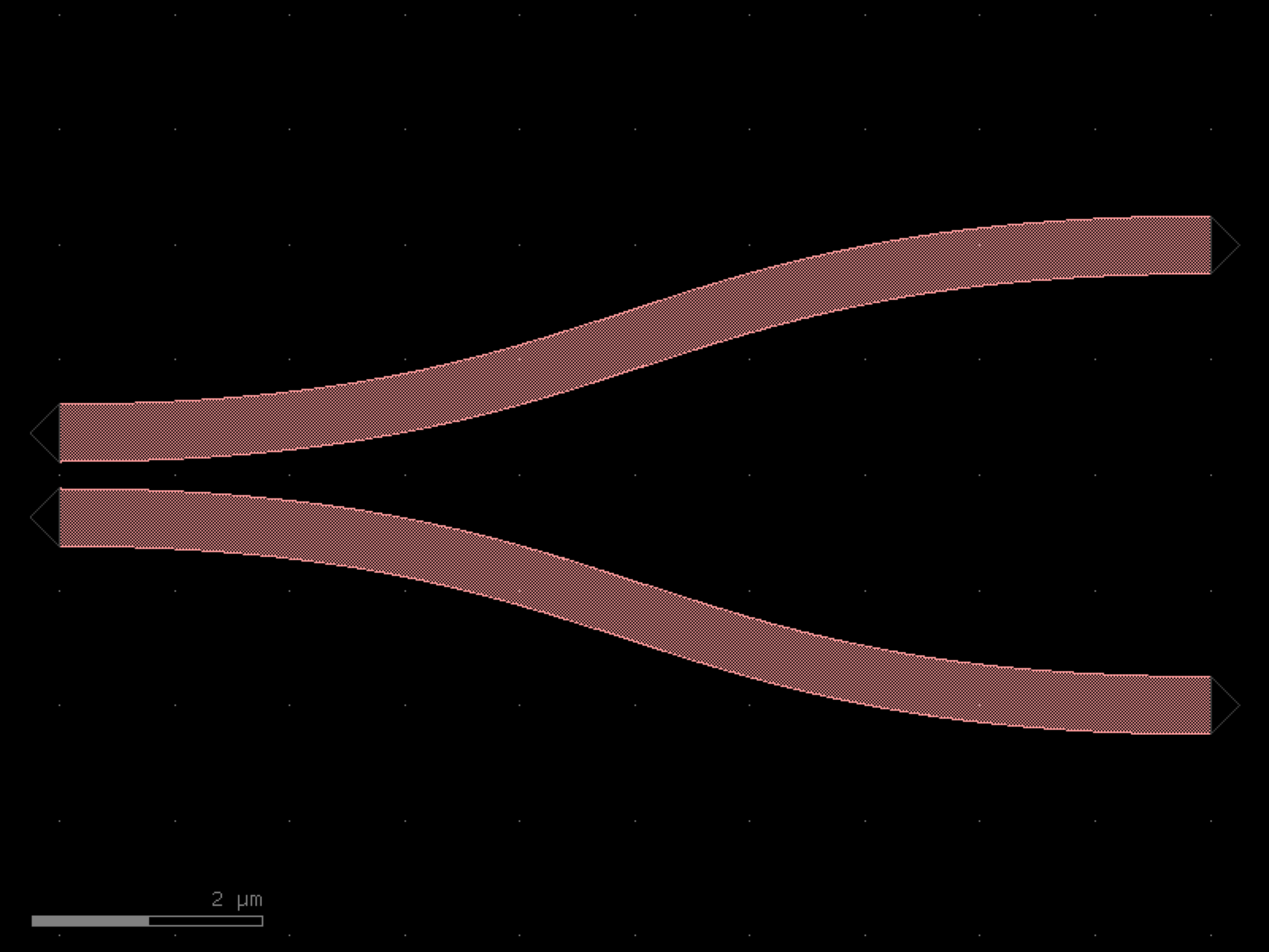
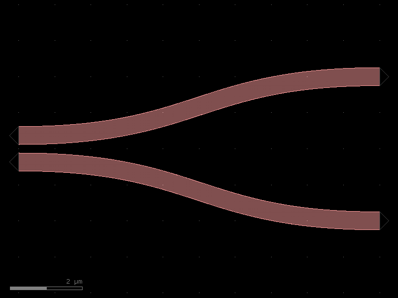
- gdsfactory.components.filters.dbr(w1=0.45, w2=0.55, l1=0.159, l2=0.159, n=10, cross_section='strip', straight_length=0.01)[source]#
Distributed Bragg Reflector.
- Parameters:
w1 (float) – thin width in um.
w2 (float) – thick width in um.
l1 (float) – thin length in um.
l2 (float) – thick length in um.
n (int) – number of periods.
cross_section (CrossSectionSpec) – cross_section spec.
straight_length (float) – length of the straight section between cutbacks.
- Return type:
   l1      l2
<-----><-------->
        _________
_______|

  w1       w2       ...  n times
_______
       |_________
import gdsfactory as gf

gf.gpdk.PDK.activate()

c = gf.components.dbr(w1=0.45, w2=0.55, l1=0.159, l2=0.159, n=10, cross_section='strip', straight_length=0.01).copy()
c.draw_ports()
c.plot()
(Source code, png, hires.png, pdf)
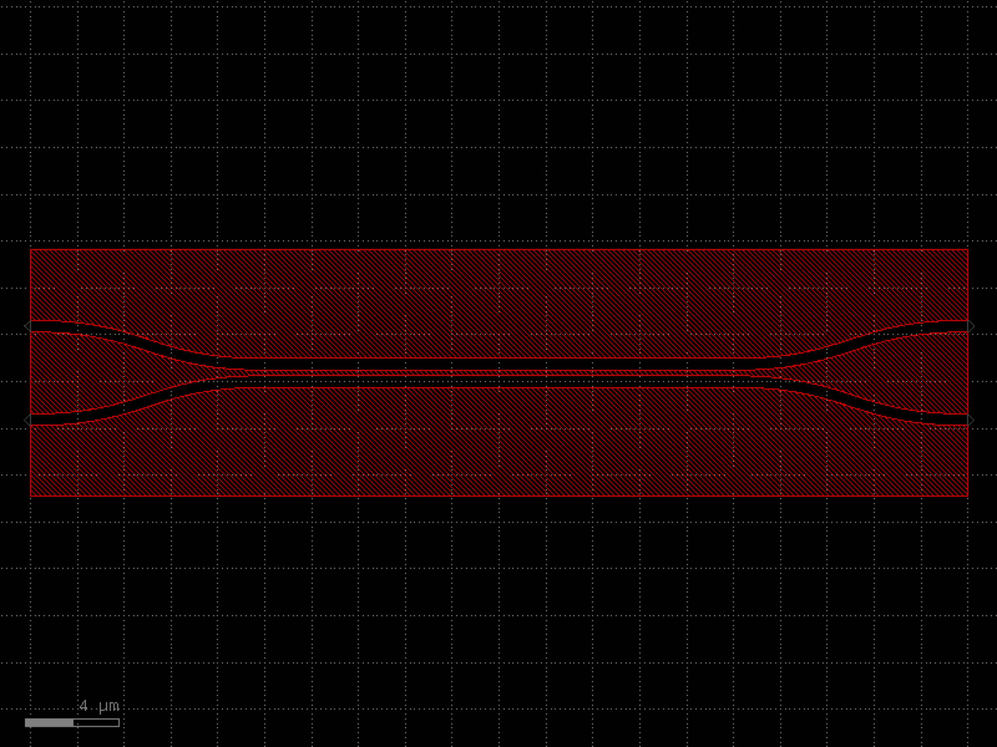

- gdsfactory.components.filters.dbr_cell(w1=0.45, w2=0.55, l1=0.159, l2=0.159, cross_section='strip')[source]#
Distributed Bragg Reflector unit cell.
- Parameters:
w1 (float) – thin width in um.
l1 (float) – thin length in um.
w2 (float) – thick width in um.
l2 (float) – thick length in um.
n – number of periods.
cross_section (CrossSectionSpec) – cross_section spec.
- Return type:
   l1      l2
<-----><-------->
        _________
_______|

  w1       w2
_______
       |_________
import gdsfactory as gf

gf.gpdk.PDK.activate()

c = gf.components.dbr_cell(w1=0.45, w2=0.55, l1=0.159, l2=0.159, cross_section='strip').copy()
c.draw_ports()
c.plot()
(Source code, png, hires.png, pdf)
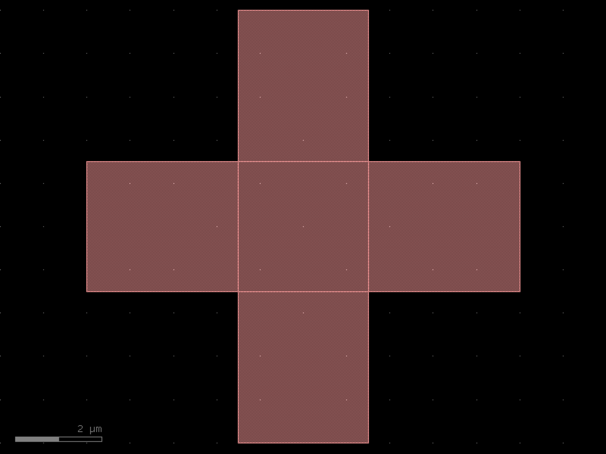
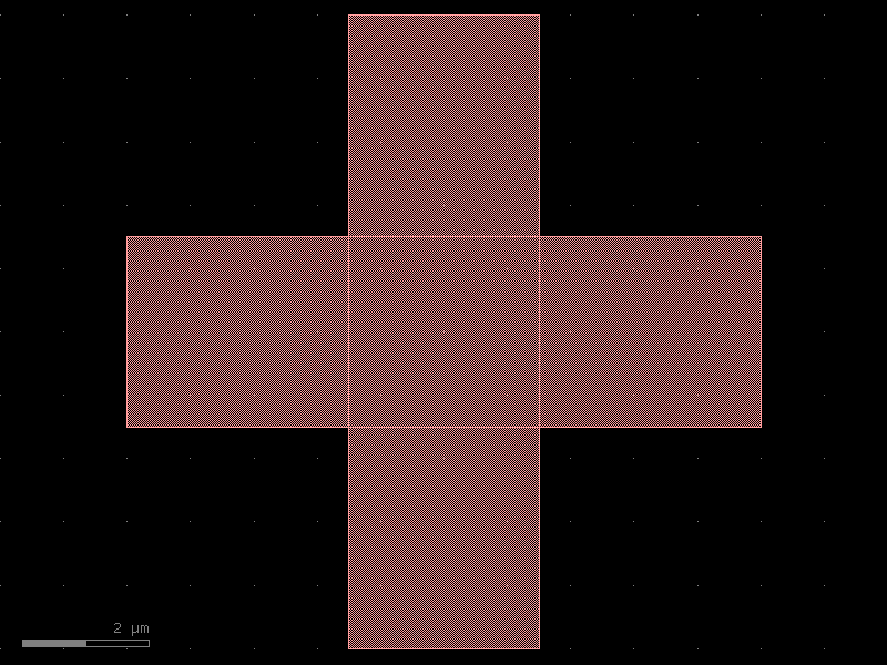
- gdsfactory.components.filters.dbr_tapered(length=10.0, period=0.85, dc=0.5, w1=0.4, w2=1.0, taper_length=20.0, fins=False, fin_size=(0.2, 0.05), cross_section='strip')[source]#
Distributed Bragg Reflector Cell class.
Tapers the input straight to a periodic straight structure with varying width (1-D photonic crystal).
- Parameters:
length (float) – Length of the DBR region.
period (float) – Period of the repeated unit.
dc (float) – Duty cycle of the repeated unit (must be a float between 0 and 1.0).
w1 (float) – thin section width. w1 = 0 corresponds to disconnected periodic blocks.
w2 (float) – wide section width.
taper_length (float) – between the input/output straight and the DBR region.
fins (bool) – If True, adds fins to the input/output straights.
fin_size (tuple[float, float]) – Specifies the x- and y-size of the fins. Defaults to 200 nm x 50 nm
cross_section (CrossSectionSpec) – cross_section spec.
- Return type:
         period
<-----><-------->
        _________
_______|

  w1       w2       ...  n times
_______
       |_________
import gdsfactory as gf

gf.gpdk.PDK.activate()

c = gf.components.dbr_tapered(length=10, period=0.85, dc=0.5, w1=0.4, w2=1, taper_length=20, fins=False, fin_size=(0.2, 0.05), cross_section='strip').copy()
c.draw_ports()
c.plot()
(Source code, png, hires.png, pdf)
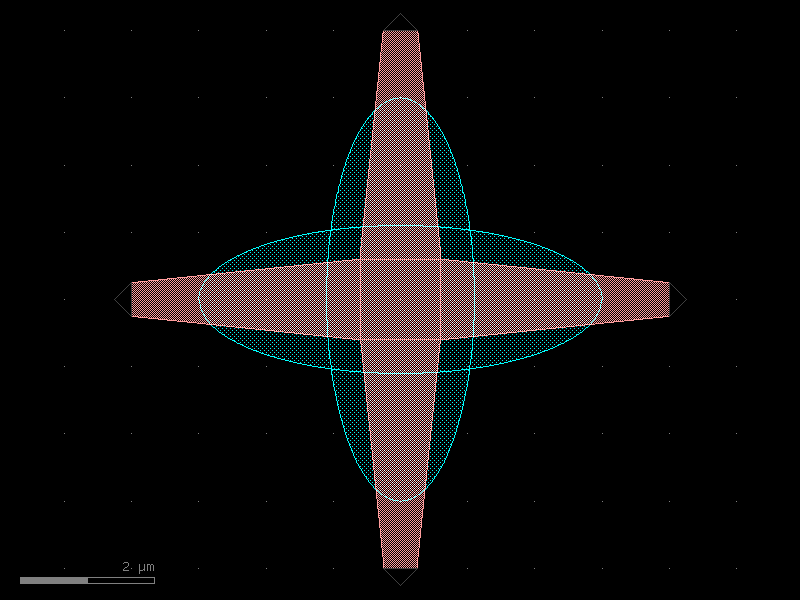

- gdsfactory.components.filters.fiber(core_diameter=10, cladding_diameter=125, layer_core='WG', layer_cladding='WGCLAD')[source]#
Returns a fiber.
- Parameters:
core_diameter (float) – in um.
cladding_diameter (float) – in um.
layer_core (LayerSpec) – layer spec for fiber core.
layer_cladding (LayerSpec) – layer spec for fiber cladding.
- Return type:
import gdsfactory as gf

gf.gpdk.PDK.activate()

c = gf.components.fiber(core_diameter=10, cladding_diameter=125, layer_core='WG', layer_cladding='WGCLAD').copy()
c.draw_ports()
c.plot()
(Source code, png, hires.png, pdf)
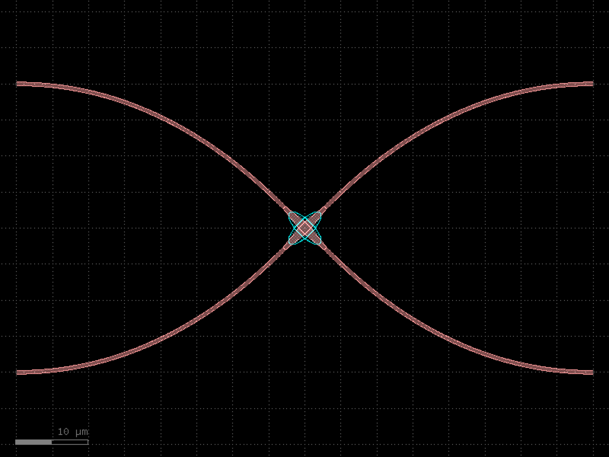
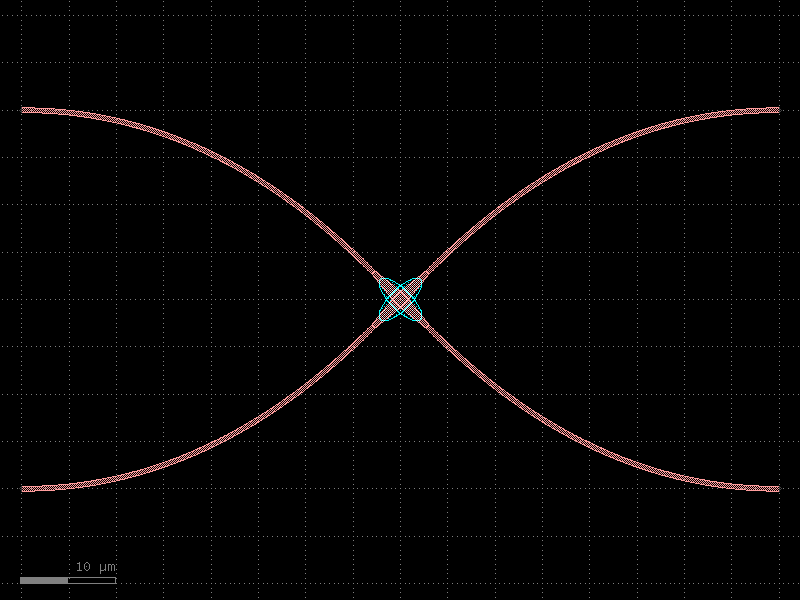
- gdsfactory.components.filters.fiber_array(n=8, pitch=127.0, core_diameter=10, cladding_diameter=125, layer_core='WG', layer_cladding='WGCLAD')[source]#
Returns a fiber array.
- Parameters:
n (int) – number of fibers.
pitch (float) – spacing.
core_diameter (float) – 10um.
cladding_diameter (float) – in um.
layer_core (LayerSpec) – layer spec for fiber core.
layer_cladding (LayerSpec) – layer spec for fiber cladding.
- Return type:
 pitch
  <->
 _________
|         | lid
| o o o o |
|         | base
|_________|
   length
import gdsfactory as gf

gf.gpdk.PDK.activate()

c = gf.components.fiber_array(n=8, pitch=127, core_diameter=10, cladding_diameter=125, layer_core='WG', layer_cladding='WGCLAD').copy()
c.draw_ports()
c.plot()
(Source code, png, hires.png, pdf)
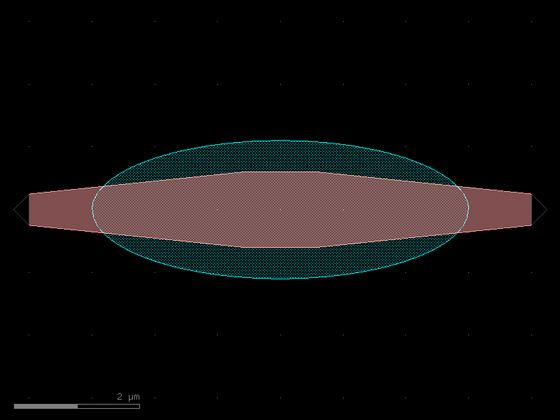
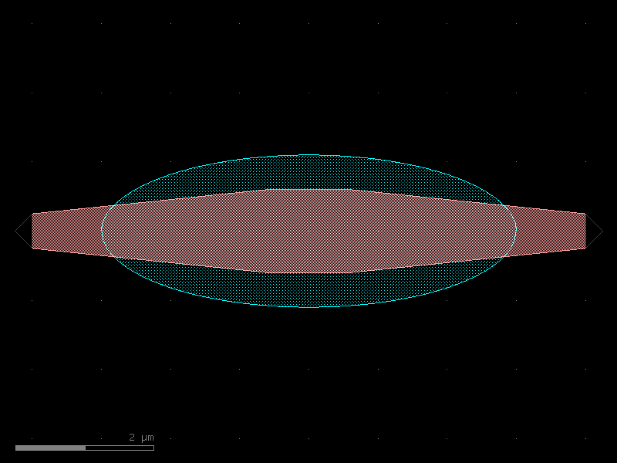

- gdsfactory.components.filters.free_propagation_region(width1=2.0, width2=20.0, length=20.0, wg_width=0.5, inputs=1, outputs=10, cross_section='strip')[source]#
Free propagation region.
- Parameters:
width1 (float) – width of the input region.
width2 (float) – width of the output region.
length (float) – length of the free propagation region.
wg_width (float) – waveguide width.
inputs (int) – number of inputs.
outputs (int) – number of outputs.
cross_section (CrossSectionSpec) – cross_section function.
- Return type:
      length
      <-->
        /|
       / |
width1|  | width2
       \ |
        \|
import gdsfactory as gf

gf.gpdk.PDK.activate()

c = gf.components.free_propagation_region(width1=2, width2=20, length=20, wg_width=0.5, inputs=1, outputs=10, cross_section='strip').copy()
c.draw_ports()
c.plot()
(Source code, png, hires.png, pdf)
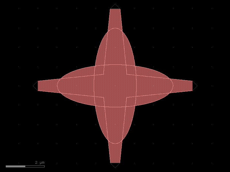
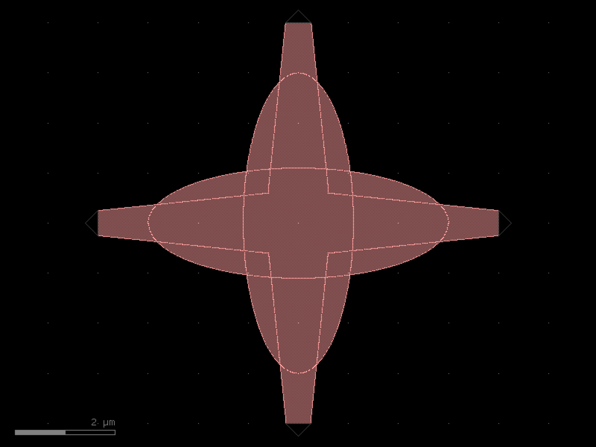

- gdsfactory.components.filters.loop_mirror(component='mmi1x2', bend90='bend_euler', cross_section='strip')[source]#
Returns Sagnac loop_mirror.
- Parameters:
component (ComponentSpec) – 1x2 splitter.
bend90 (ComponentSpec) – 90 deg bend.
cross_section (CrossSectionSpec) – cross_section settings.
- Return type:
import gdsfactory as gf

gf.gpdk.PDK.activate()

c = gf.components.loop_mirror(component='mmi1x2', bend90='bend_euler', cross_section='strip').copy()
c.draw_ports()
c.plot()
(Source code, png, hires.png, pdf)
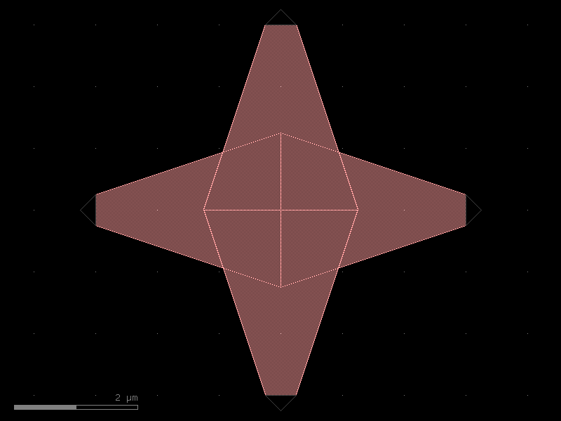
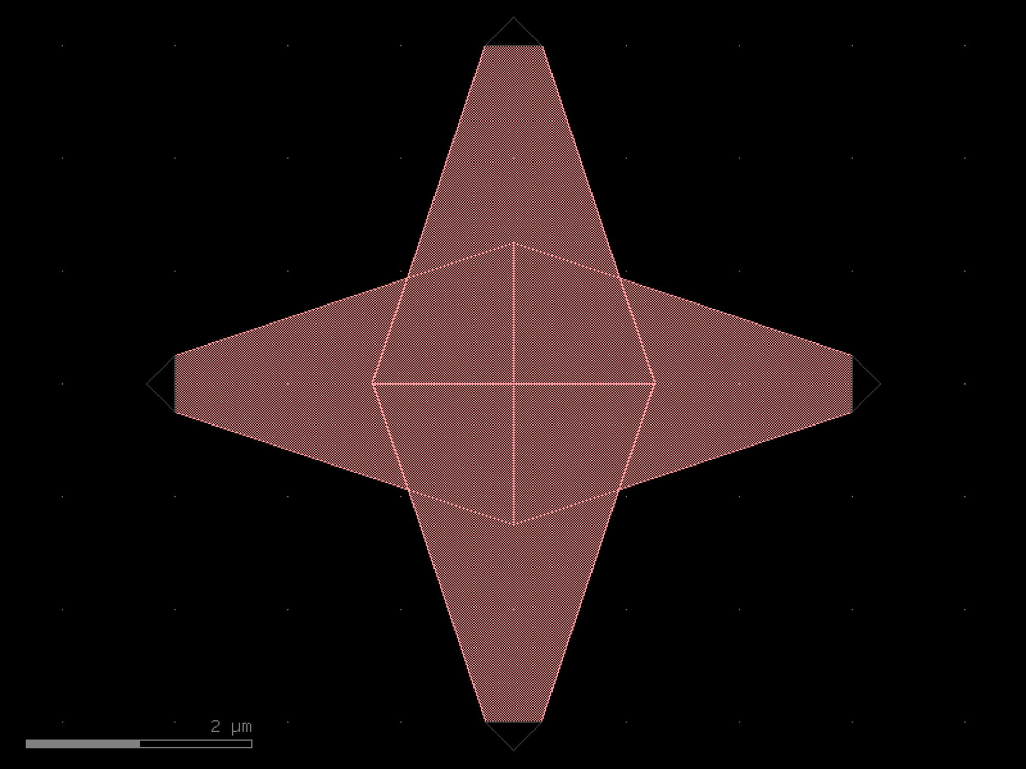

- gdsfactory.components.filters.mode_converter(gap=0.3, length=10, coupler_straight_asymmetric='coupler_straight_asymmetric', bend=functools.partial(<function bend_s>, size=(25, 3)), taper='taper', mm_width=1.2, mc_mm_width=1, sm_width=0.5, taper_length=25, cross_section='strip')[source]#
Returns Mode converter from TE0 to TE1.
By matching the effective indices of two waveguides with different widths, light can couple from different transverse modes e.g. TE0 <-> TE1. https://doi.org/10.1109/JPHOT.2019.2941742
- Parameters:
gap (float) – directional coupler gap.
length (float) – coupler length interaction.
coupler_straight_asymmetric (ComponentSpec) – spec.
bend (ComponentSpec) – spec.
taper (ComponentSpec) – spec.
mm_width (float) – input/output multimode waveguide width.
mc_mm_width (float) – mode converter multimode waveguide width
sm_width (float) – single mode waveguide width.
taper_length (float) – taper length.
cross_section (CrossSectionSpec) – cross_section spec.
- Return type:
o2 ---           --- o4
      \         /
       \       /
        -------
o1 -----=======----- o3
        |-----|
        length

= : multimode width
- : singlemode width
import gdsfactory as gf

gf.gpdk.PDK.activate()

c = gf.components.mode_converter(gap=0.3, length=10, coupler_straight_asymmetric='coupler_straight_asymmetric', taper='taper', mm_width=1.2, mc_mm_width=1, sm_width=0.5, taper_length=25, cross_section='strip').copy()
c.draw_ports()
c.plot()
(Source code, png, hires.png, pdf)
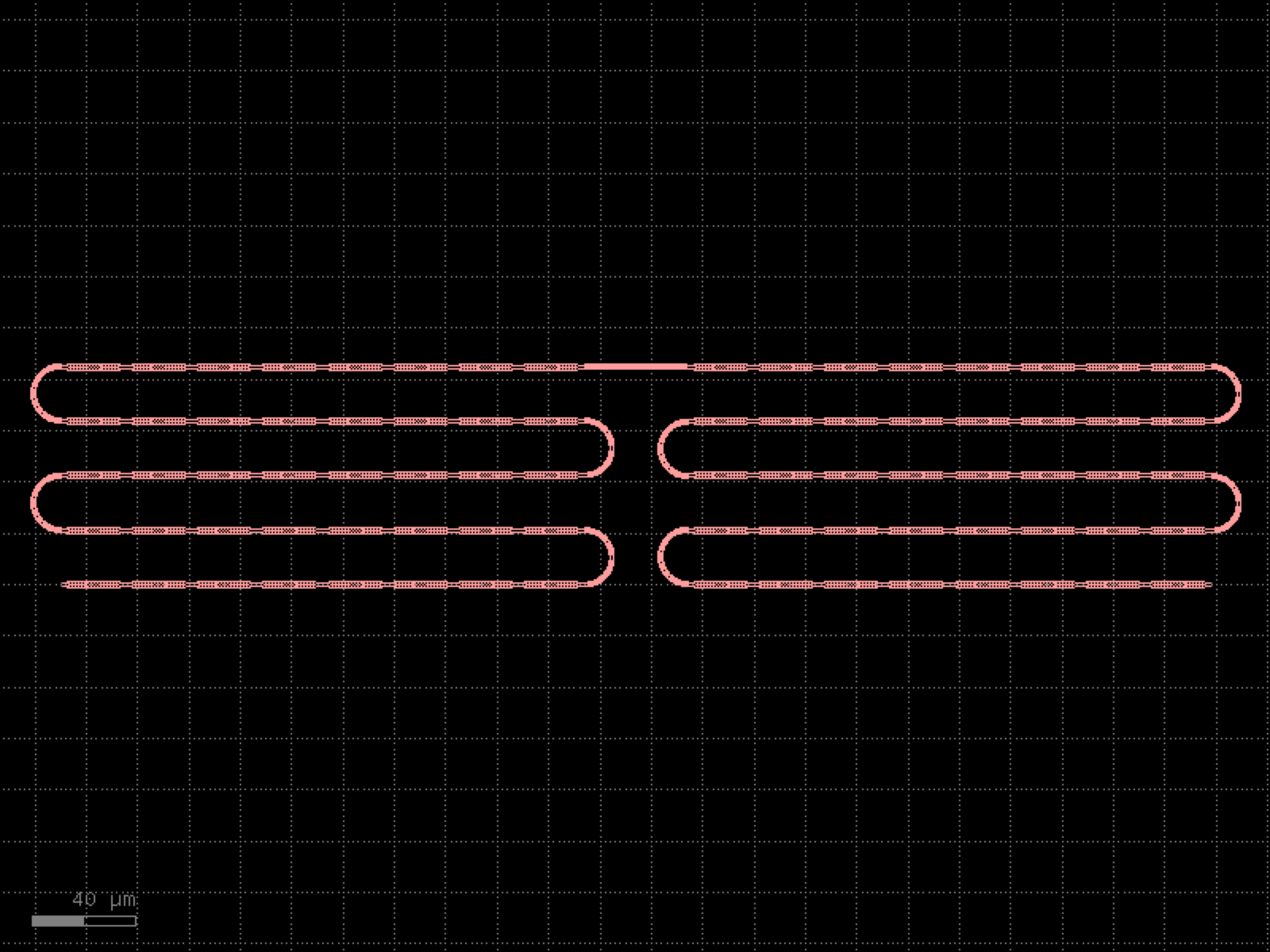
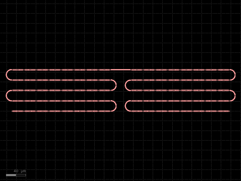
- gdsfactory.components.filters.polarization_splitter_rotator(width_taper_in=(0.54, 0.69, 0.83), length_taper_in=(4.0, 44.0), width_coupler=(0.9, 0.404), length_coupler=7.0, gap=0.15, width_out=0.54, length_out=14.33, dy=5.0, cross_section='strip')[source]#
Returns polarization splitter rotator.
“Novel concept for ultracompact polarization splitter-rotator based on silicon nanowires.” By D. Dai, and J. E. Bowers (Optics express vol 19, no. 11 pp. 10940-10949 (2011)).
- Parameters:
width_taper_in (tuple[float, float, float]) – Three west widths of the input tapers in um.
length_taper_in (tuple[float, float] | tuple[float, float, float]) – Two or three length of the bend regions in um.
width_coupler (tuple[float, float]) – Top and bottom widths of the coupling region in um.
length_coupler (float) – Length of the coupling region in um.
gap (float) – Distance between the coupler in um.
width_out (float) – Width of the splitter region in um.
length_out (float) – Length of the splitter region in um.
dy (float) – Port-to-port distance between the splitter region in um.
cross_section (CrossSectionSpec) – cross-section spec.
- Return type:
Notes
The length of third input taper is automatically determined if only two lengths are in arguments.
import gdsfactory as gf

gf.gpdk.PDK.activate()

c = gf.components.polarization_splitter_rotator(width_taper_in=(0.54, 0.69, 0.83), length_taper_in=(4, 44), width_coupler=(0.9, 0.404), length_coupler=7, gap=0.15, width_out=0.54, length_out=14.33, dy=5, cross_section='strip').copy()
c.draw_ports()
c.plot()
(Source code, png, hires.png, pdf)
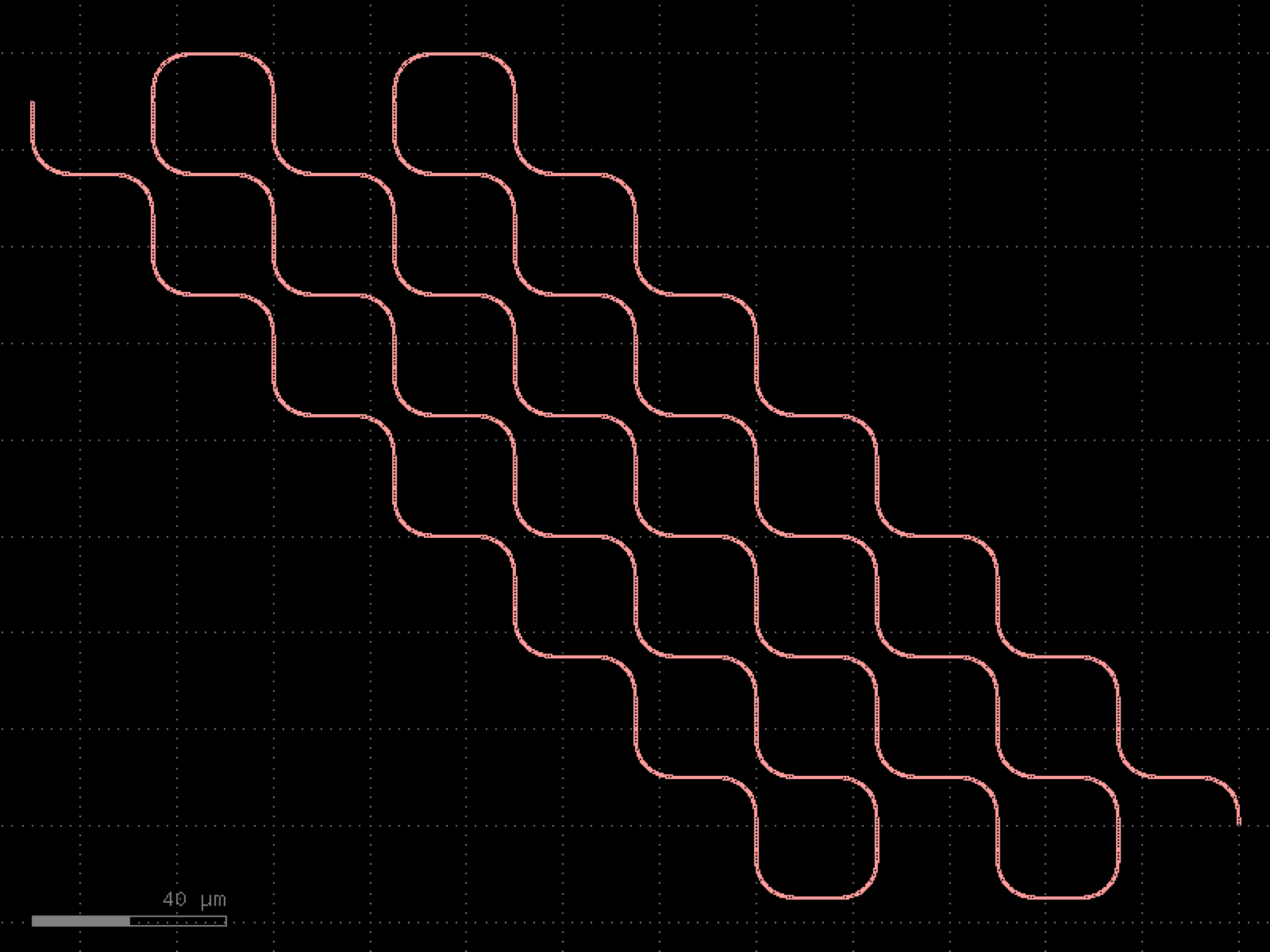
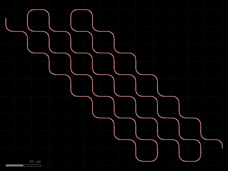
- gdsfactory.components.filters.terminator(length=50, cross_section_input=<function strip>, cross_section_tip=None, tapered_width=0.2, doping_layers=('NPP', ), doping_offset=1.0)[source]#
Returns doped taper to terminate waveguides.
- Parameters:
length (float | None) – distance between input and narrow tapered end.
cross_section_input (CrossSectionSpec) – input cross-section.
cross_section_tip (CrossSectionSpec | None) – cross-section at the end of the termination.
tapered_width (float) – width of the default cross-section at the end of the termination. Only used if cross_section_tip is not None.
doping_layers (LayerSpecs) – doping layers to superimpose on the taper. Default N++.
doping_offset (float) – offset of the doping layer beyond the bbox
- Return type:
gf.Component
import gdsfactory as gf

gf.gpdk.PDK.activate()

c = gf.components.terminator(length=50, tapered_width=0.2, doping_layers=('NPP',), doping_offset=1).copy()
c.draw_ports()
c.plot()
(Source code, png, hires.png, pdf)
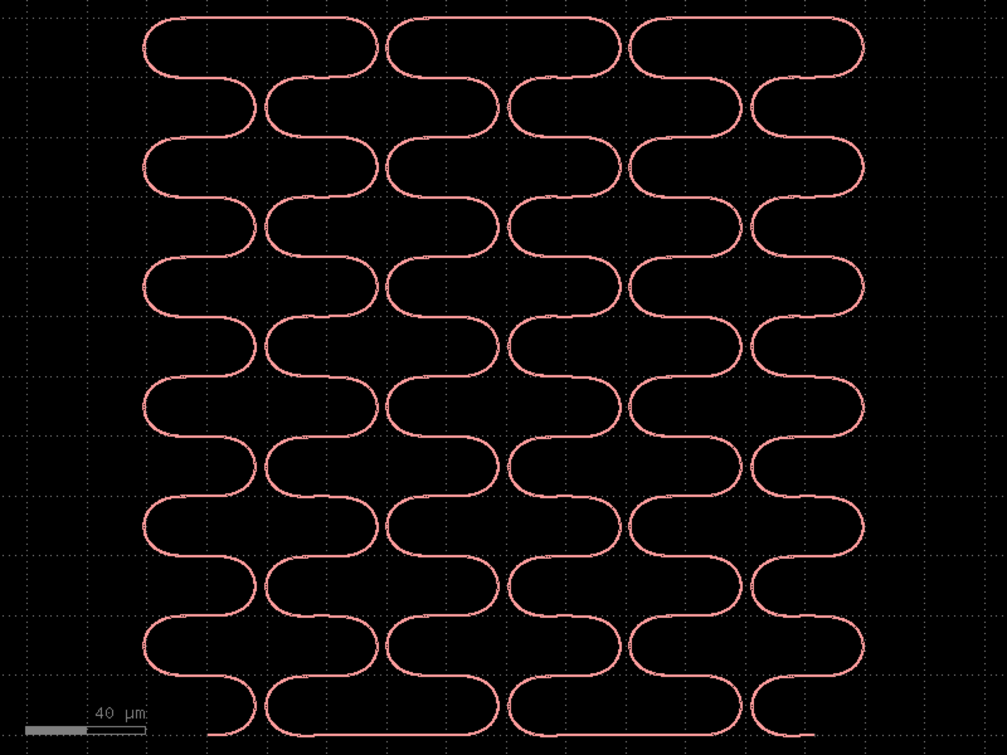
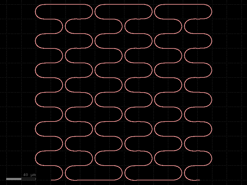
- gdsfactory.components.filters.terminator_spiral(separation=3.0, width_tip=0.2, number_of_loops=1, npoints=1000, min_bend_radius=None, cross_section='strip')[source]#
Returns doped taper to terminate waveguides.
- Parameters:
separation (float) – separation between the loops.
width_tip (float) – width of the default cross-section at the end of the termination. Only used if cross_section_tip is not None.
number_of_loops (float) – number of loops in the spiral.
npoints (int) – points for the spiral.
min_bend_radius (float | None) – minimum bend radius for the spiral.
cross_section (CrossSectionSpec) – input cross-section.
- Return type:
import gdsfactory as gf

gf.gpdk.PDK.activate()

c = gf.components.terminator_spiral(separation=3, width_tip=0.2, number_of_loops=1, npoints=1000, cross_section='strip').copy()
c.draw_ports()
c.plot()
(Source code, png, hires.png, pdf)
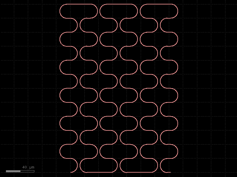
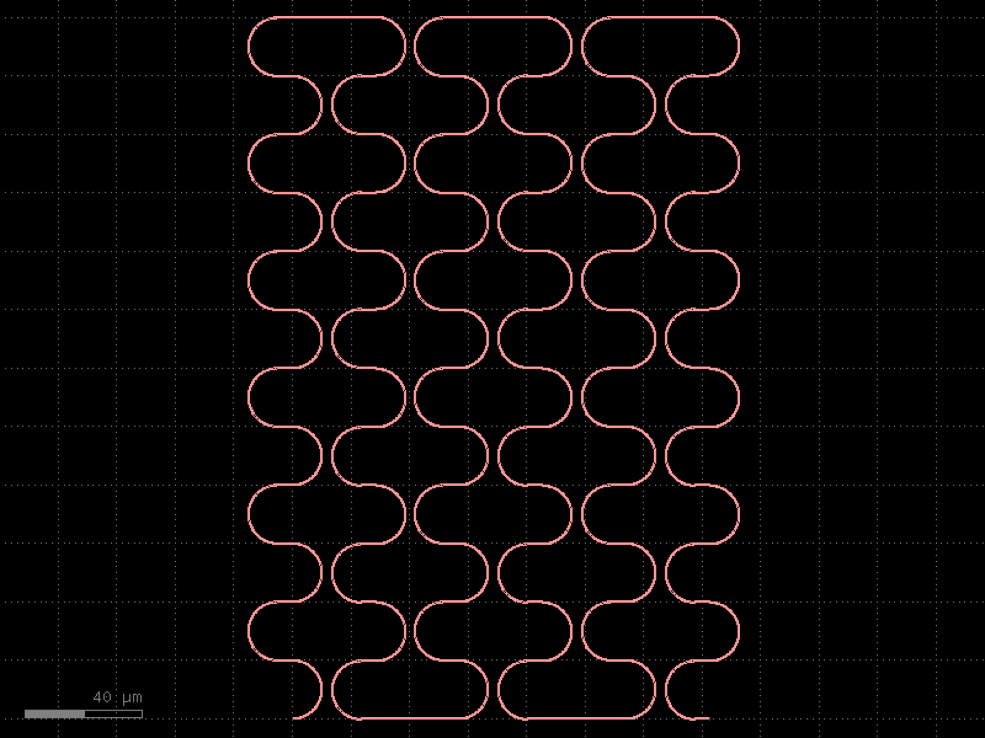

grating_couplers#
- gdsfactory.components.grating_couplers.grating_coupler_array(grating_coupler='grating_coupler_elliptical', pitch=127.0, n=6, port_name='o1', rotation=-90, with_loopback=False, cross_section='strip', straight_to_grating_spacing=10.0, centered=True, radius=None, bend='bend_euler', mirror_grating_coupler=False)[source]#
Array of grating couplers.
- Parameters:
grating_coupler (ComponentSpec) – ComponentSpec.
pitch (float) – x spacing.
n (int) – number of grating couplers.
port_name (str) – port name.
rotation (int) – rotation angle for each reference.
with_loopback (bool) – if True, adds a loopback between edge GCs. Only works for rotation = 90 for now.
cross_section (CrossSectionSpec) – cross_section for the routing.
straight_to_grating_spacing (float) – spacing between the last grating coupler and the loopback.
centered (bool) – if True, centers the array around the origin.
radius (float | None) – optional radius for routing the loopback.
bend (ComponentSpec) – ComponentSpec for the bend used in the loopback.
mirror_grating_coupler (bool) – if True, mirrors the grating coupler.
- Return type:
import gdsfactory as gf

gf.gpdk.PDK.activate()

c = gf.components.grating_coupler_array(grating_coupler='grating_coupler_elliptical', pitch=127, n=6, port_name='o1', rotation=-90, with_loopback=False, cross_section='strip', straight_to_grating_spacing=10, centered=True, bend='bend_euler', mirror_grating_coupler=False).copy()
c.draw_ports()
c.plot()
(Source code, png, hires.png, pdf)
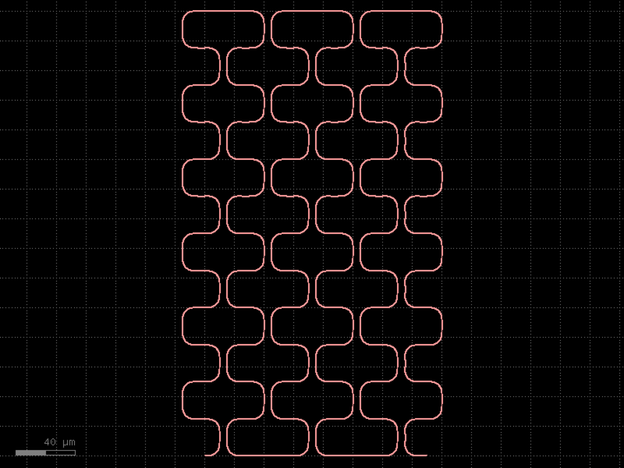
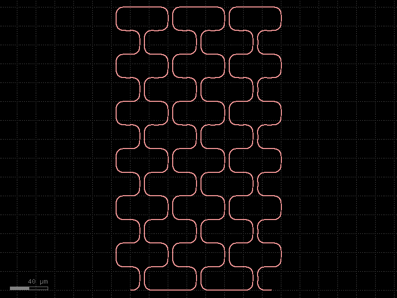
- gdsfactory.components.grating_couplers.grating_coupler_dual_pol(unit_cell=<function _unit_cell>, period_x=0.58, period_y=0.58, x_span=11, y_span=11, length_taper=150.0, width_taper=10.0, polarization='te', wavelength=1.55, taper='taper', base_layer='WG', cross_section='strip')[source]#
2 dimensional, dual polarization grating coupler.
Based on a photonic crystal with a unit cell that is usually an ellipse, a rectangle or a circle. # The default values are loosely based on Taillaert et al, # “A Compact Two-Dimensional Grating Coupler Used as a Polarization Splitter”, IEEE Phot. Techn. Lett. 15(9), 2003
- Parameters:
unit_cell (ComponentSpec) – component describing the unit cell of the photonic crystal.
period_x (float) – spacing between unit cells in the x direction [um].
period_y (float) – spacing between unit cells in the y direction [um].
x_span (float) – full x span of the photonic crystal.
y_span (float) – full y span of the photonic crystal.
length_taper (float) – taper length [um].
width_taper (float) – width of the taper at the grating coupler side [um].
polarization (str) – polarization of the grating coupler.
wavelength (float) – operation wavelength [um]
taper (ComponentSpec) – function to generate the tapers.
base_layer (LayerSpec) – layer to draw over the whole photonic crystal (necessary if the unit cells are etched into a base layer).
cross_section (CrossSectionSpec) – for the routing waveguides.
- Return type:
side view
              fiber

           /  /  /  /
          /  /  /  /

        _|-|_|-|_|-|___  --> unit_cells
           base_layer |
    o1  ______________|


top view

           -------------
       // | o   o   o  |
o1 __ //  | o   o   o  |
      \\  | o   o   o  |
       \\ | o   o   o  |
           -------------
           \\         //
            \\       //
                 |
                 o2
import gdsfactory as gf

gf.gpdk.PDK.activate()

c = gf.components.grating_coupler_dual_pol(period_x=0.58, period_y=0.58, x_span=11, y_span=11, length_taper=150, width_taper=10, polarization='te', wavelength=1.55, taper='taper', base_layer='WG', cross_section='strip').copy()
c.draw_ports()
c.plot()
(Source code, png, hires.png, pdf)
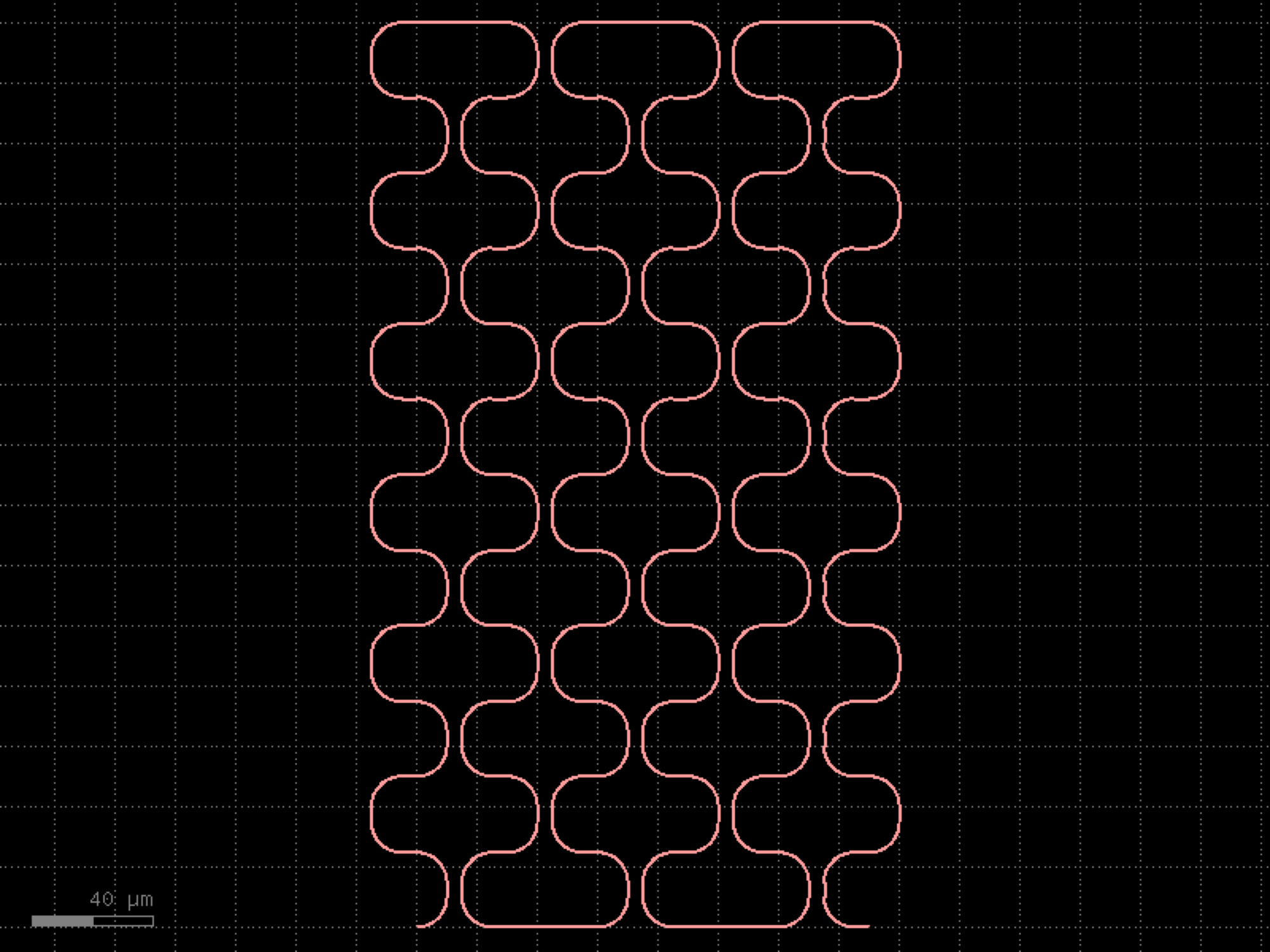
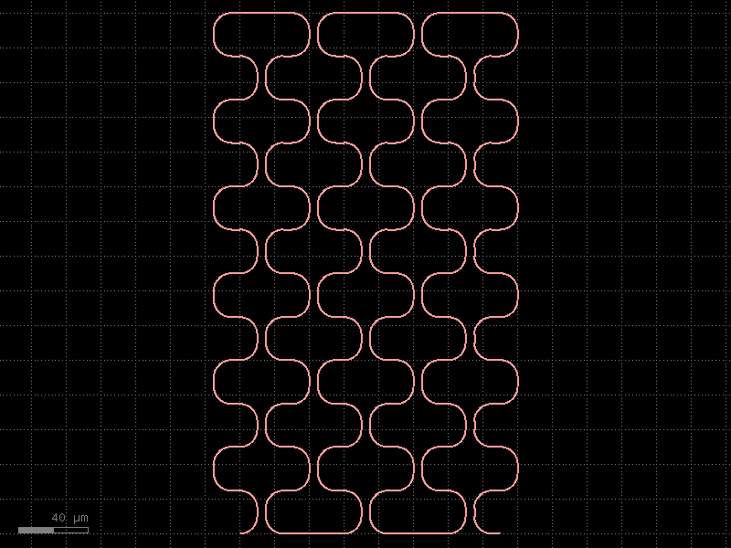
- gdsfactory.components.grating_couplers.grating_coupler_elliptical(polarization='te', taper_length=16.6, taper_angle=40.0, wavelength=1.554, fiber_angle=15.0, grating_line_width=0.343, neff=2.638, nclad=1.443, n_periods=30, big_last_tooth=False, layer_slab='SLAB150', slab_xmin=-1.0, slab_offset=2.0, spiked=True, cross_section='strip')[source]#
Grating coupler with parametrization based on Lumerical FDTD simulation.
- Parameters:
polarization (str) – te or tm.
taper_length (float) – taper length from input.
taper_angle (float) – grating flare angle.
wavelength (float) – grating transmission central wavelength (um).
fiber_angle (float) – fibre angle in degrees determines ellipticity.
grating_line_width (float) – in um.
neff (float) – tooth effective index.
nclad (float) – cladding effective index.
n_periods (int) – number of periods.
big_last_tooth (bool) – adds a big_last_tooth.
layer_slab (LayerSpec | None) – layer that protects the slab under the grating.
slab_xmin (float) – where 0 is at the start of the taper.
slab_offset (float) – in um.
spiked (bool) – grating teeth have sharp spikes to avoid non-manhattan drc errors.
cross_section (CrossSectionSpec) – specification (CrossSection, string or dict).
- Return type:
          fiber

       /  /  /  /
      /  /  /  /

    _|-|_|-|_|-|___ layer
       layer_slab |
o1  ______________|
import gdsfactory as gf

gf.gpdk.PDK.activate()

c = gf.components.grating_coupler_elliptical(polarization='te', taper_length=16.6, taper_angle=40, wavelength=1.554, fiber_angle=15, grating_line_width=0.343, neff=2.638, nclad=1.443, n_periods=30, big_last_tooth=False, layer_slab='SLAB150', slab_xmin=-1, slab_offset=2, spiked=True, cross_section='strip').copy()
c.draw_ports()
c.plot()
(Source code, png, hires.png, pdf)
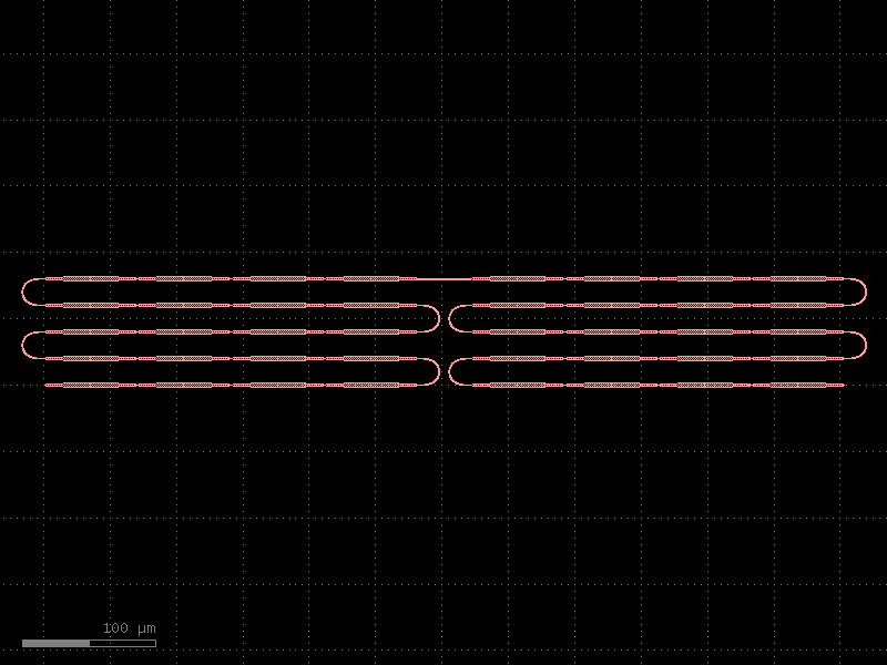
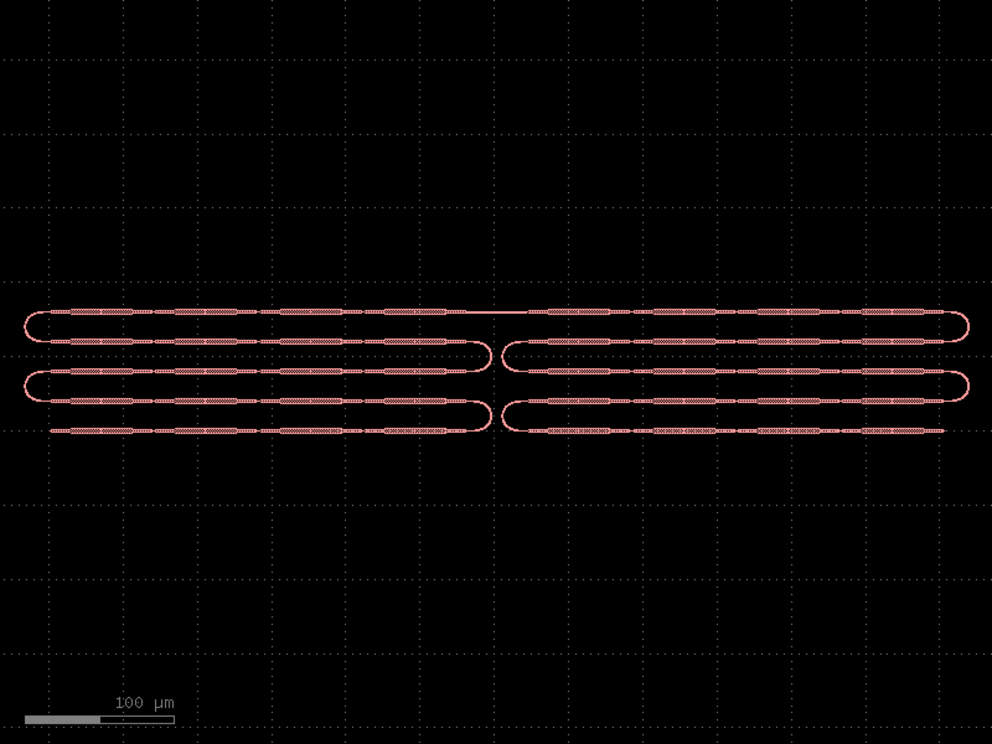

- gdsfactory.components.grating_couplers.grating_coupler_elliptical_arbitrary(gaps=(0.1, 0.1, 0.1, 0.1, 0.1, 0.1, 0.1, 0.1, 0.1, 0.1), widths=(0.5, 0.5, 0.5, 0.5, 0.5, 0.5, 0.5, 0.5, 0.5, 0.5), taper_length=16.6, taper_angle=60.0, wavelength=1.554, fiber_angle=15.0, nclad=1.443, layer_slab='SLAB150', layer_grating=None, taper_to_slab_offset=-3.0, polarization='te', spiked=True, bias_gap=0, cross_section='strip')[source]#
Grating coupler with parametrization based on Lumerical FDTD simulation.
The ellipticity is derived from Lumerical knowledge base it depends on fiber_angle (degrees), neff, and nclad
- Parameters:
gaps (Floats) – list of gaps.
widths (Floats) – list of widths.
taper_length (float) – taper length from input.
taper_angle (float) – grating flare angle.
wavelength (float) – grating transmission central wavelength (um).
fiber_angle (float) – fibre angle in degrees determines ellipticity.
nclad (float) – cladding effective index to compute ellipticity.
layer_slab (LayerSpec | None) – Optional slab.
layer_grating (LayerSpec | None) – Optional layer for grating. by default None uses cross_section.layer. if different from cross_section.layer expands taper.
taper_to_slab_offset (float) – 0 is where taper ends.
polarization (str) – te or tm.
spiked (bool) – grating teeth have spikes to avoid drc errors.
bias_gap (float) – etch gap (um). Positive bias increases gap and reduces width to keep period constant.
cross_section (CrossSectionSpec) – cross_section spec for waveguide port.
- Return type:
https://en.wikipedia.org/wiki/Ellipse c = (a1 ** 2 - b1 ** 2) ** 0.5 e = (1 - (b1 / a1) ** 2) ** 0.5 print(e)
          fiber

       /  /  /  /
      /  /  /  /

    _|-|_|-|_|-|___ layer
       layer_slab |
o1  ______________|
import gdsfactory as gf

gf.gpdk.PDK.activate()

c = gf.components.grating_coupler_elliptical_arbitrary(gaps=(0.1, 0.1, 0.1, 0.1, 0.1, 0.1, 0.1, 0.1, 0.1, 0.1), widths=(0.5, 0.5, 0.5, 0.5, 0.5, 0.5, 0.5, 0.5, 0.5, 0.5), taper_length=16.6, taper_angle=60, wavelength=1.554, fiber_angle=15, nclad=1.443, layer_slab='SLAB150', taper_to_slab_offset=-3, polarization='te', spiked=True, bias_gap=0, cross_section='strip').copy()
c.draw_ports()
c.plot()
(Source code, png, hires.png, pdf)
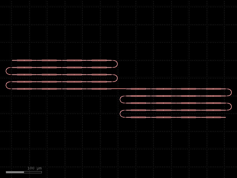

- gdsfactory.components.grating_couplers.grating_coupler_elliptical_lumerical(parameters=(-2.4298362615732447, 0.1, 0.48007023217536954, 0.1, 0.607397685752365, 0.1, 0.4498844003086115, 0.1, 0.4274116312627637, 0.1, 0.4757904248387285, 0.1, 0.5026649898504233, 0.10002922416240886, 0.5100366774007897, 0.1, 0.494399635363353, 0.1079599958465788, 0.47400592737426483, 0.14972685326277918, 0.43272750134545823, 0.1839530796530385, 0.3872023336708212, 0.2360175325711591, 0.36032212454768675, 0.24261846353500535, 0.35770350120764394, 0.2606637836858316, 0.3526104381544335, 0.24668202254540886, 0.3717488388788273, 0.22920754299702897, 0.37769616507688464, 0.2246528336925301, 0.3765437598650894, 0.22041773376471022, 0.38047596041838994, 0.21923601658169187, 0.3798873698864591, 0.21700438236445285, 0.38291698672245644, 0.21827768053295463, 0.3641322152037017, 0.23729077006065105, 0.3676834419346081, 0.24865079519725933, 0.34415050295044936, 0.2733570818755685, 0.3306230780901629, 0.27350446437732157), layer_slab='SLAB150', taper_angle=55, taper_length=12.6, fiber_angle=5, info=None, bias_gap=0, cross_section='strip')[source]#
Returns a grating coupler from lumerical inverse design 3D optimization.
this is a wrapper of components.grating_coupler_elliptical_arbitrary https://support.lumerical.com/hc/en-us/articles/1500000306621 https://support.lumerical.com/hc/en-us/articles/360042800573
Here are the simulation settings used in lumerical
n_bg=1.44401 #Refractive index of the background material (cladding) wg=3.47668 # Refractive index of the waveguide material (core) lambda0=1550e-9 bandwidth = 0e-9 polarization = ‘TE’ wg_width=500e-9 # Waveguide width wg_height=220e-9 # Waveguide height etch_depth=80e-9 # etch depth theta_fib_mat = 5 # Angle of the fiber mode in material theta_taper=30 efficiency=0.55 # 5.2 dB
- Parameters:
parameters (Floats) – xinput, gap1, width1, gap2, width2 …
layer – for waveguide.
layer_slab (LayerSpec | None) – for slab.
taper_angle (float) – in deg.
taper_length (float) – in um.
fiber_angle (float) – used to compute ellipticity.
info (dict[str, Any] | None) – optional simulation settings.
bias_gap (float) – gap/trenches bias (um) to compensate for etching bias.
cross_section (CrossSectionSpec)
- Keyword Arguments:
taper_length – taper length from input in um.
taper_angle – grating flare angle in degrees.
wavelength – grating transmission central wavelength (um).
fiber_angle – fibre angle in degrees determines ellipticity.
neff – tooth effective index.
nclad – cladding effective index.
polarization – te or tm.
spiked – grating teeth include sharp spikes to avoid non-manhattan drc errors.
cross_section – cross_section spec for waveguide port.
- Return type:
import gdsfactory as gf

gf.gpdk.PDK.activate()

c = gf.components.grating_coupler_elliptical_lumerical(parameters=(-2.43, 0.1, 0.48, 0.1, 0.607, 0.1, 0.45, 0.1, 0.427, 0.1, 0.476, 0.1, 0.503, 0.1, 0.51, 0.1, 0.494, 0.108, 0.474, 0.15, 0.433, 0.184, 0.387, 0.236, 0.36, 0.243, 0.358, 0.261, 0.353, 0.247, 0.372, 0.229, 0.378, 0.225, 0.377, 0.22, 0.38, 0.219, 0.38, 0.217, 0.383, 0.218, 0.364, 0.237, 0.368, 0.249, 0.344, 0.273, 0.331, 0.274), layer_slab='SLAB150', taper_angle=55, taper_length=12.6, fiber_angle=5, bias_gap=0, cross_section='strip').copy()
c.draw_ports()
c.plot()
(Source code, png, hires.png, pdf)
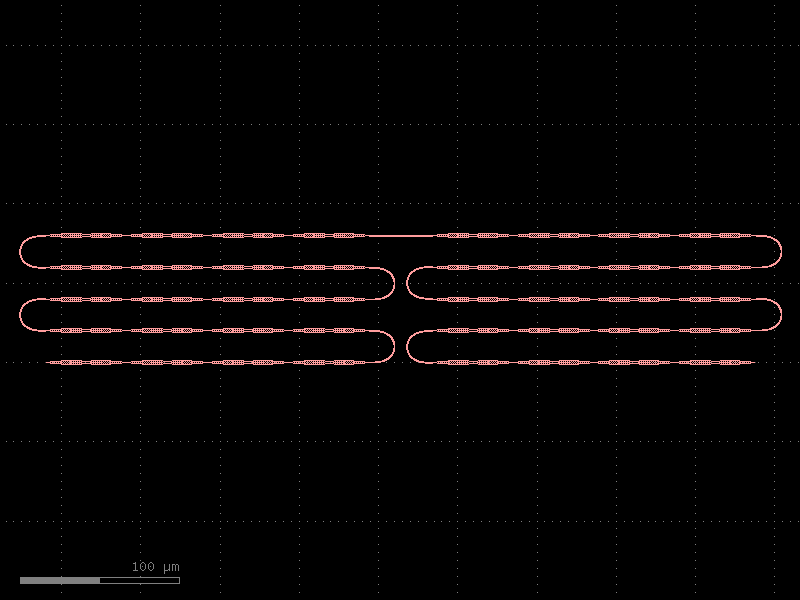

- gdsfactory.components.grating_couplers.grating_coupler_elliptical_lumerical_etch70(parameters=(-2.4298362615732447, 0.1, 0.48007023217536954, 0.1, 0.607397685752365, 0.1, 0.4498844003086115, 0.1, 0.4274116312627637, 0.1, 0.4757904248387285, 0.1, 0.5026649898504233, 0.10002922416240886, 0.5100366774007897, 0.1, 0.494399635363353, 0.1079599958465788, 0.47400592737426483, 0.14972685326277918, 0.43272750134545823, 0.1839530796530385, 0.3872023336708212, 0.2360175325711591, 0.36032212454768675, 0.24261846353500535, 0.35770350120764394, 0.2606637836858316, 0.3526104381544335, 0.24668202254540886, 0.3717488388788273, 0.22920754299702897, 0.37769616507688464, 0.2246528336925301, 0.3765437598650894, 0.22041773376471022, 0.38047596041838994, 0.21923601658169187, 0.3798873698864591, 0.21700438236445285, 0.38291698672245644, 0.21827768053295463, 0.3641322152037017, 0.23729077006065105, 0.3676834419346081, 0.24865079519725933, 0.34415050295044936, 0.2733570818755685, 0.3306230780901629, 0.27350446437732157), layer_slab='SLAB150', taper_angle=55, taper_length=12.6, fiber_angle=5, *, info={'efficiency': 0.55, 'etch_depth': 0.08, 'fiber_angle': 5, 'gap_min': 0.1, 'link': 'https://support.lumerical.com/hc/en-us/articles/1500000306621', 'width_min': 0.1}, bias_gap=0, cross_section='strip')#
Returns a grating coupler from lumerical inverse design 3D optimization.
this is a wrapper of components.grating_coupler_elliptical_arbitrary https://support.lumerical.com/hc/en-us/articles/1500000306621 https://support.lumerical.com/hc/en-us/articles/360042800573
Here are the simulation settings used in lumerical
n_bg=1.44401 #Refractive index of the background material (cladding) wg=3.47668 # Refractive index of the waveguide material (core) lambda0=1550e-9 bandwidth = 0e-9 polarization = ‘TE’ wg_width=500e-9 # Waveguide width wg_height=220e-9 # Waveguide height etch_depth=80e-9 # etch depth theta_fib_mat = 5 # Angle of the fiber mode in material theta_taper=30 efficiency=0.55 # 5.2 dB
- Parameters:
parameters (Floats) – xinput, gap1, width1, gap2, width2 …
layer – for waveguide.
layer_slab (LayerSpec | None) – for slab.
taper_angle (float) – in deg.
taper_length (float) – in um.
fiber_angle (float) – used to compute ellipticity.
info (dict[str, Any] | None) – optional simulation settings.
bias_gap (float) – gap/trenches bias (um) to compensate for etching bias.
cross_section (CrossSectionSpec)
- Keyword Arguments:
taper_length – taper length from input in um.
taper_angle – grating flare angle in degrees.
wavelength – grating transmission central wavelength (um).
fiber_angle – fibre angle in degrees determines ellipticity.
neff – tooth effective index.
nclad – cladding effective index.
polarization – te or tm.
spiked – grating teeth include sharp spikes to avoid non-manhattan drc errors.
cross_section – cross_section spec for waveguide port.
- Return type:
import gdsfactory as gf

gf.gpdk.PDK.activate()

c = gf.components.grating_coupler_elliptical_lumerical_etch70(parameters=(-2.43, 0.1, 0.48, 0.1, 0.607, 0.1, 0.45, 0.1, 0.427, 0.1, 0.476, 0.1, 0.503, 0.1, 0.51, 0.1, 0.494, 0.108, 0.474, 0.15, 0.433, 0.184, 0.387, 0.236, 0.36, 0.243, 0.358, 0.261, 0.353, 0.247, 0.372, 0.229, 0.378, 0.225, 0.377, 0.22, 0.38, 0.219, 0.38, 0.217, 0.383, 0.218, 0.364, 0.237, 0.368, 0.249, 0.344, 0.273, 0.331, 0.274), layer_slab='SLAB150', taper_angle=55, taper_length=12.6, fiber_angle=5, bias_gap=0, cross_section='strip').copy()
c.draw_ports()
c.plot()
(Source code, png, hires.png, pdf)
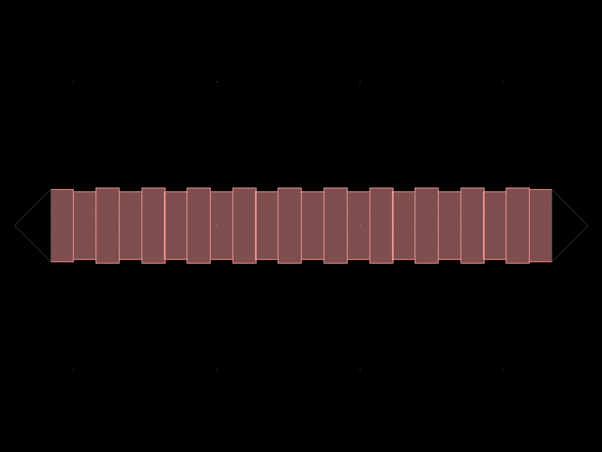
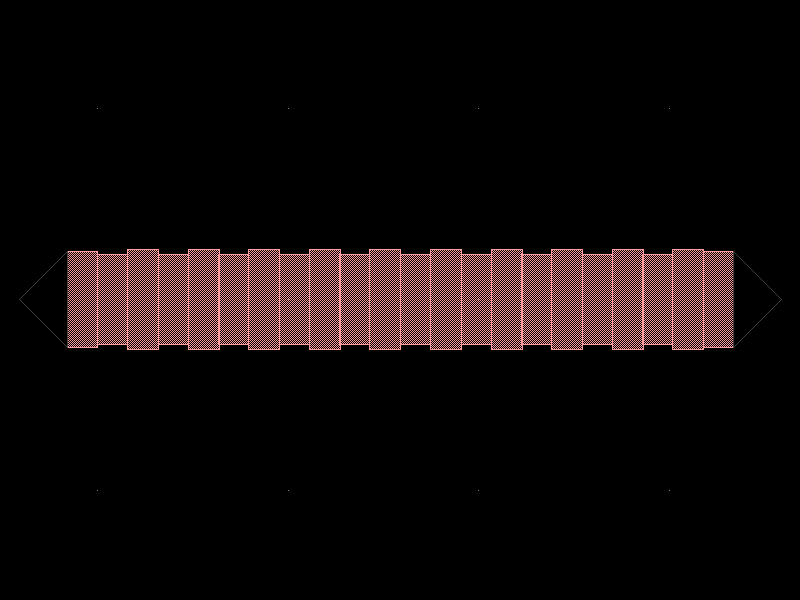
- gdsfactory.components.grating_couplers.grating_coupler_elliptical_trenches(polarization='te', taper_length=16.6, taper_angle=30.0, trenches_extra_angle=9.0, wavelength=1.53, fiber_angle=15.0, grating_line_width=0.343, neff=2.638, ncladding=1.443, layer_trench='SHALLOW_ETCH', p_start=26, n_periods=30, end_straight_length=0.2, taper='taper', cross_section='strip')[source]#
Returns Grating coupler with defined trenches.
Some foundries define the grating coupler by a shallow etch step (trenches) Others define the slab that they keep (see grating_coupler_elliptical)
- Parameters:
polarization (str) – ‘te’ or ‘tm’.
taper_length (float) – taper length from straight I/O.
taper_angle (float) – grating flare angle.
trenches_extra_angle (float) – extra angle for the trenches.
wavelength (float) – grating transmission central wavelength.
fiber_angle (float) – fibre polish angle in degrees.
grating_line_width (float) – of the 220 ridge.
neff (float) – tooth effective index.
ncladding (float) – cladding index.
layer_trench (LayerSpec) – for the trench.
p_start (int) – first tooth.
n_periods (int) – number of grating teeth.
end_straight_length (float) – at the end of straight.
taper (ComponentSpec) – taper function.
cross_section (CrossSectionSpec) – cross_section spec.
- Return type:
              fiber

           /  /  /  /
          /  /  /  /
        _|-|_|-|_|-|___
WG  o1  ______________|
import gdsfactory as gf

gf.gpdk.PDK.activate()

c = gf.components.grating_coupler_elliptical_trenches(polarization='te', taper_length=16.6, taper_angle=30, trenches_extra_angle=9, wavelength=1.53, fiber_angle=15, grating_line_width=0.343, neff=2.638, ncladding=1.443, layer_trench='SHALLOW_ETCH', p_start=26, n_periods=30, end_straight_length=0.2, taper='taper', cross_section='strip').copy()
c.draw_ports()
c.plot()
(Source code, png, hires.png, pdf)
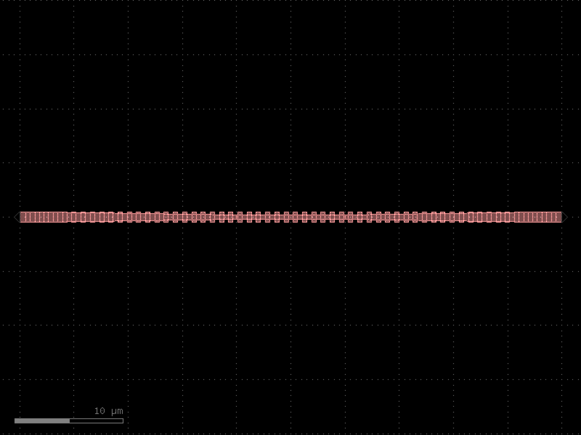
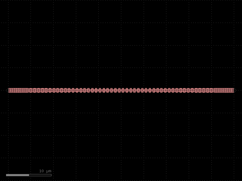
- gdsfactory.components.grating_couplers.grating_coupler_elliptical_uniform(n_periods=20, period=0.75, fill_factor=0.5, **kwargs)[source]#
Grating coupler with parametrization based on Lumerical FDTD simulation.
The ellipticity is derived from Lumerical knowledge base it depends on fiber_angle (degrees), neff, and nclad
- Parameters:
n_periods (int) – number of grating periods.
period (float) – grating pitch in um.
fill_factor (float) – ratio of grating width vs gap.
kwargs (Any)
- Keyword Arguments:
taper_length – taper length from input.
taper_angle – grating flare angle.
wavelength – grating transmission central wavelength (um).
fiber_angle – fibre angle in degrees determines ellipticity.
neff – tooth effective index to compute ellipticity.
nclad – cladding effective index to compute ellipticity.
layer_slab – Optional slab.
taper_to_slab_offset – where 0 is at the start of the taper.
polarization – te or tm.
spiked – grating teeth have spikes to avoid drc errors..
bias_gap – etch gap (um). Positive bias increases gap and reduces width to keep period constant.
cross_section – cross_section spec for waveguide port.
kwargs – cross_section settings.
- Return type:
          fiber

       /  /  /  /
      /  /  /  /

    _|-|_|-|_|-|___ layer
       layer_slab |
o1  ______________|
import gdsfactory as gf

gf.gpdk.PDK.activate()

c = gf.components.grating_coupler_elliptical_uniform(n_periods=20, period=0.75, fill_factor=0.5).copy()
c.draw_ports()
c.plot()
(Source code, png, hires.png, pdf)
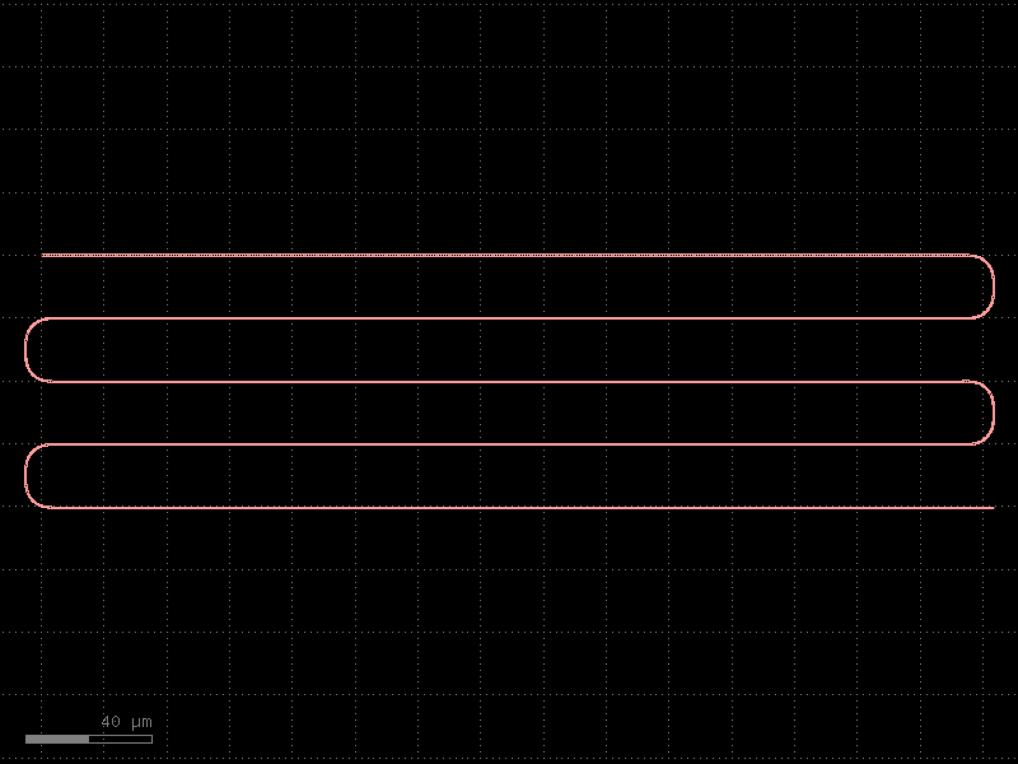

- gdsfactory.components.grating_couplers.grating_coupler_loss(pitch=127.0, grating_coupler='grating_coupler_elliptical_trenches', cross_section='strip', port_name='o1', rotation=-90, nfibers=10, grating_coupler_spacing=5.0)[source]#
Grating coupler test structure for de-embeding fiber array.
Connects channel 1->3, 1->5 … 1->nfibers with grating couplers.
Only odd channels are connected to the grating couplers as even channels in the align_tree.
- Parameters:
pitch (float) – um.
grating_coupler (ComponentSpec) – spec.
cross_section (CrossSectionSpec) – spec.
port_name (str) – for the grating_coupler port.
rotation (float) – degrees.
nfibers (int) – number of fibers to connect.
grating_coupler_spacing (float) – um.
- Return type:
import gdsfactory as gf

gf.gpdk.PDK.activate()

c = gf.components.grating_coupler_loss(pitch=127, grating_coupler='grating_coupler_elliptical_trenches', cross_section='strip', port_name='o1', rotation=-90, nfibers=10, grating_coupler_spacing=5).copy()
c.draw_ports()
c.plot()
(Source code, png, hires.png, pdf)
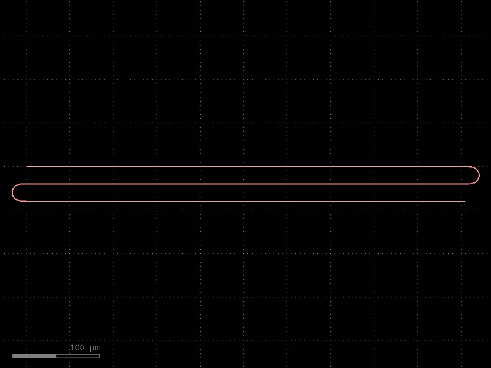
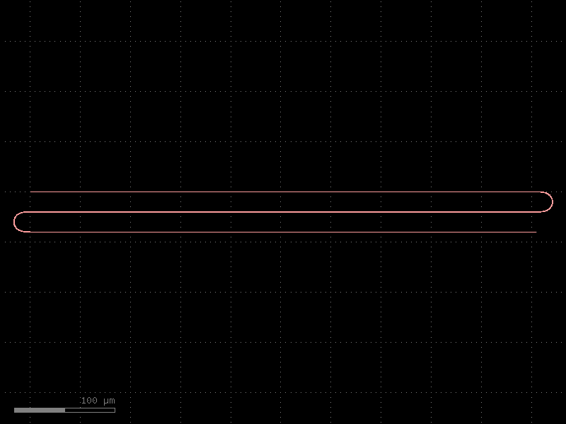
- gdsfactory.components.grating_couplers.grating_coupler_rectangular(n_periods=20, period=0.75, fill_factor=0.5, width_grating=11.0, length_taper=150.0, polarization='te', wavelength=1.55, taper='taper', layer_slab='SLAB150', layer_grating=None, fiber_angle=15, slab_xmin=-1.0, slab_offset=1.0, cross_section='strip')[source]#
Grating coupler with rectangular shapes (not elliptical).
Needs longer taper than elliptical. Grating teeth are straight. For a focusing grating take a look at grating_coupler_elliptical.
- Parameters:
n_periods (int) – number of grating teeth.
period (float) – grating pitch.
fill_factor (float) – ratio of grating width vs gap.
width_grating (float) –
length_taper (float) –
polarization (str) – ‘te’ or ‘tm’.
wavelength (float) – in um.
taper (ComponentSpec) – function.
layer_slab (LayerSpec | None) – layer that protects the slab under the grating.
layer_grating (LayerSpec | None) – layer for the grating.
fiber_angle (float) – in degrees.
slab_xmin (float) – where 0 is at the start of the taper.
slab_offset (float) – from edge of grating to edge of the slab.
cross_section (CrossSectionSpec) – for input waveguide port.
- Return type:
side view
              fiber

           /  /  /  /
          /  /  /  /

        _|-|_|-|_|-|___ layer
           layer_slab |
    o1  ______________|


top view     _________
            /| | | | |
           / | | | | |
          /taper_angle
         /_ _| | | | |
wg_width |   | | | | |
         \   | | | | |
          \  | | | | |
           \ | | | | |
            \|_|_|_|_|
         <-->
        taper_length
import gdsfactory as gf

gf.gpdk.PDK.activate()

c = gf.components.grating_coupler_rectangular(n_periods=20, period=0.75, fill_factor=0.5, width_grating=11, length_taper=150, polarization='te', wavelength=1.55, taper='taper', layer_slab='SLAB150', fiber_angle=15, slab_xmin=-1, slab_offset=1, cross_section='strip').copy()
c.draw_ports()
c.plot()
(Source code, png, hires.png, pdf)
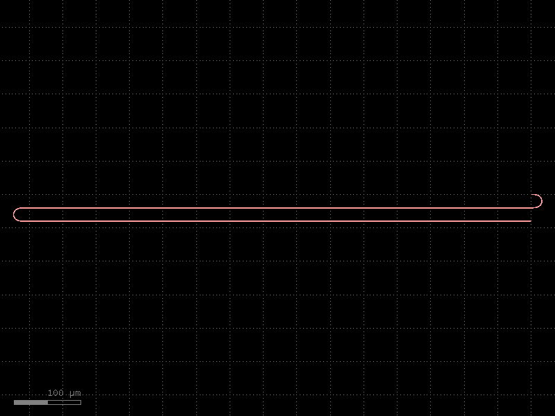
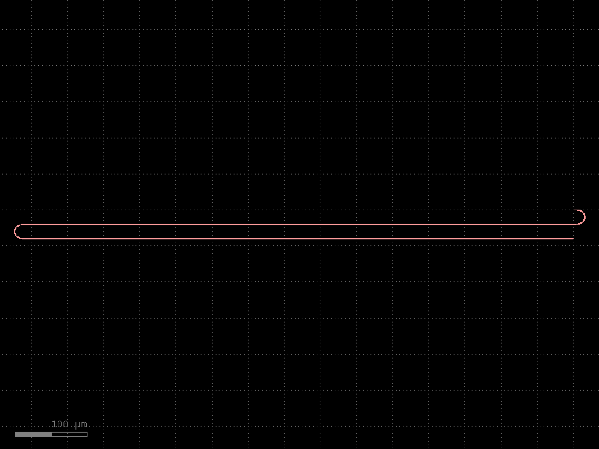

- gdsfactory.components.grating_couplers.grating_coupler_rectangular_arbitrary(gaps=(0.2, 0.2, 0.2, 0.2, 0.2, 0.2, 0.2, 0.2, 0.2, 0.2), widths=(0.5, 0.5, 0.5, 0.5, 0.5, 0.5, 0.5, 0.5, 0.5, 0.5), width_grating=11.0, length_taper=150.0, polarization='te', wavelength=1.55, layer_grating=None, layer_slab=None, slab_xmin=-1.0, slab_offset=1.0, fiber_angle=15, cross_section='strip')[source]#
Grating coupler uniform with rectangular shape (not elliptical).
Therefore it needs a longer taper. Grating teeth are straight instead of elliptical.
- Parameters:
gaps (Floats) – list of gaps between grating teeth.
widths (Floats) – list of grating widths.
width_grating (float) – grating teeth width.
length_taper (float) – taper length (um).
polarization (str) – ‘te’ or ‘tm’.
wavelength (float) – in um.
layer_grating (LayerSpec | None) – Optional layer for grating. by default None uses cross_section.layer. if different from cross_section.layer expands taper.
layer_slab (LayerSpec | None) – layer that protects the slab under the grating.
slab_xmin (float) – where 0 is at the start of the taper.
slab_offset (float) – from edge of grating to edge of the slab.
fiber_angle (float) – in degrees.
cross_section (CrossSectionSpec) – for input waveguide port.
- Return type:
              fiber

           /  /  /  /
          /  /  /  /

        _|-|_|-|_|-|___ layer
           layer_slab |
    o1  ______________|


top view     _________
            /| | | | |
           / | | | | |
          /taper_angle
         /_ _| | | | |
wg_width |   | | | | |
         \   | | | | |
          \  | | | | |
           \ | | | | |
            \|_|_|_|_|
         <-->
        taper_length
import gdsfactory as gf

gf.gpdk.PDK.activate()

c = gf.components.grating_coupler_rectangular_arbitrary(gaps=(0.2, 0.2, 0.2, 0.2, 0.2, 0.2, 0.2, 0.2, 0.2, 0.2), widths=(0.5, 0.5, 0.5, 0.5, 0.5, 0.5, 0.5, 0.5, 0.5, 0.5), width_grating=11, length_taper=150, polarization='te', wavelength=1.55, slab_xmin=-1, slab_offset=1, fiber_angle=15, cross_section='strip').copy()
c.draw_ports()
c.plot()
(Source code, png, hires.png, pdf)
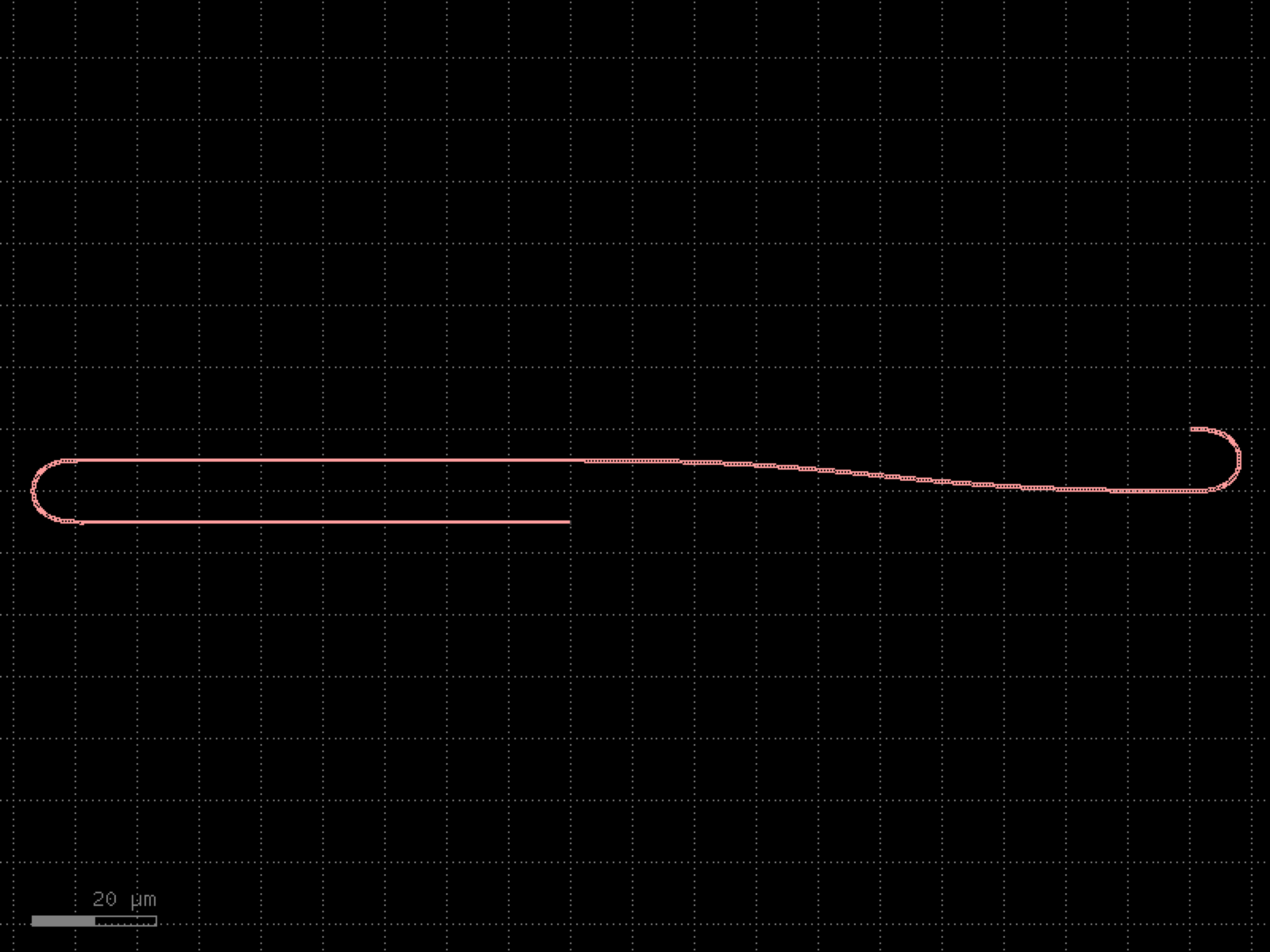

- gdsfactory.components.grating_couplers.grating_coupler_tree(n=4, straight_spacing=4.0, grating_coupler='grating_coupler_elliptical_te', with_loopback=False, bend='bend_euler', fanout_length=0.0, cross_section='strip', **kwargs)[source]#
Array of straights connected with grating couplers.
useful to align the 4 corners of the chip
- Parameters:
n (int) – number of gratings.
straight_spacing (float) – in um.
grating_coupler (ComponentSpec) – spec.
with_loopback (bool) – adds loopback.
bend (ComponentSpec) – bend spec.
fanout_length (float) – in um.
cross_section (CrossSectionSpec) – cross_section function.
kwargs (Any) – additional arguments.
- Return type:
import gdsfactory as gf

gf.gpdk.PDK.activate()

c = gf.components.grating_coupler_tree(n=4, straight_spacing=4, grating_coupler='grating_coupler_elliptical_te', with_loopback=False, bend='bend_euler', fanout_length=0, cross_section='strip').copy()
c.draw_ports()
c.plot()
(Source code, png, hires.png, pdf)

mems#
- gdsfactory.components.mems.anchored_flexure(hinge_width=0.3, hinge_length=5.0, pad_width=10.0, pad_length=10.0, layer='WG', port_type='electrical')[source]#
Returns a flexure hinge between two pads.
Two rectangular pads connected by a thin hinge, all centered vertically.
- Parameters:
hinge_width (float) – width of the thin flexure hinge.
hinge_length (float) – length of the hinge connecting the two pads.
pad_width (float) – width (vertical) of each pad.
pad_length (float) – length (horizontal) of each pad.
layer (LayerSpec) – layer spec.
port_type (str) – port type for electrical ports.
- Return type:
import gdsfactory as gf

gf.gpdk.PDK.activate()

c = gf.components.anchored_flexure(hinge_width=0.3, hinge_length=5, pad_width=10, pad_length=10, layer='WG', port_type='electrical').copy()
c.draw_ports()
c.plot()
(Source code, png, hires.png, pdf)
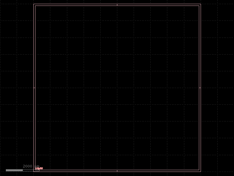
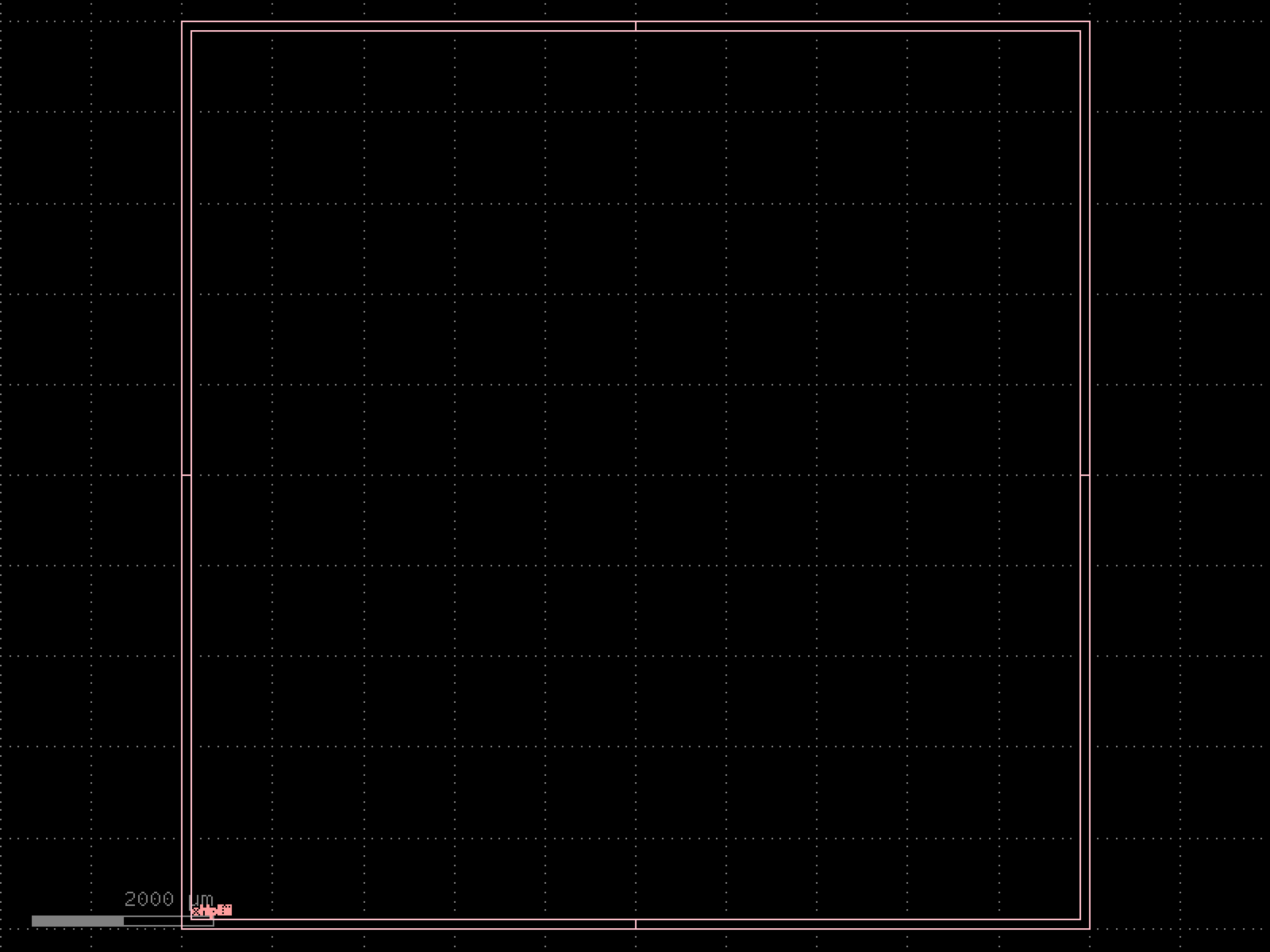

- gdsfactory.components.mems.bent_beam(beam_width=1.0, beam_length=40.0, bend_angle=170.0, anchor_width=5.0, anchor_length=5.0, layer='WG', port_type='electrical')[source]#
Returns a V-shaped bent beam thermal actuator.
Two straight beam segments meeting at an apex that points upward, with anchor pads at both ends.
- Parameters:
beam_width (float) – width of the beam.
beam_length (float) – length of each beam segment (center-line).
bend_angle (float) – angle between the two beam segments in degrees.
anchor_width (float) – width (vertical) of each anchor pad.
anchor_length (float) – length (horizontal) of each anchor pad.
layer (LayerSpec) – layer spec.
port_type (str) – port type for electrical ports.
- Return type:
import gdsfactory as gf

gf.gpdk.PDK.activate()

c = gf.components.bent_beam(beam_width=1, beam_length=40, bend_angle=170, anchor_width=5, anchor_length=5, layer='WG', port_type='electrical').copy()
c.draw_ports()
c.plot()
(Source code, png, hires.png, pdf)
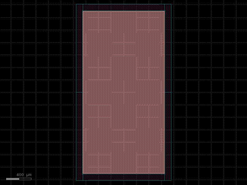
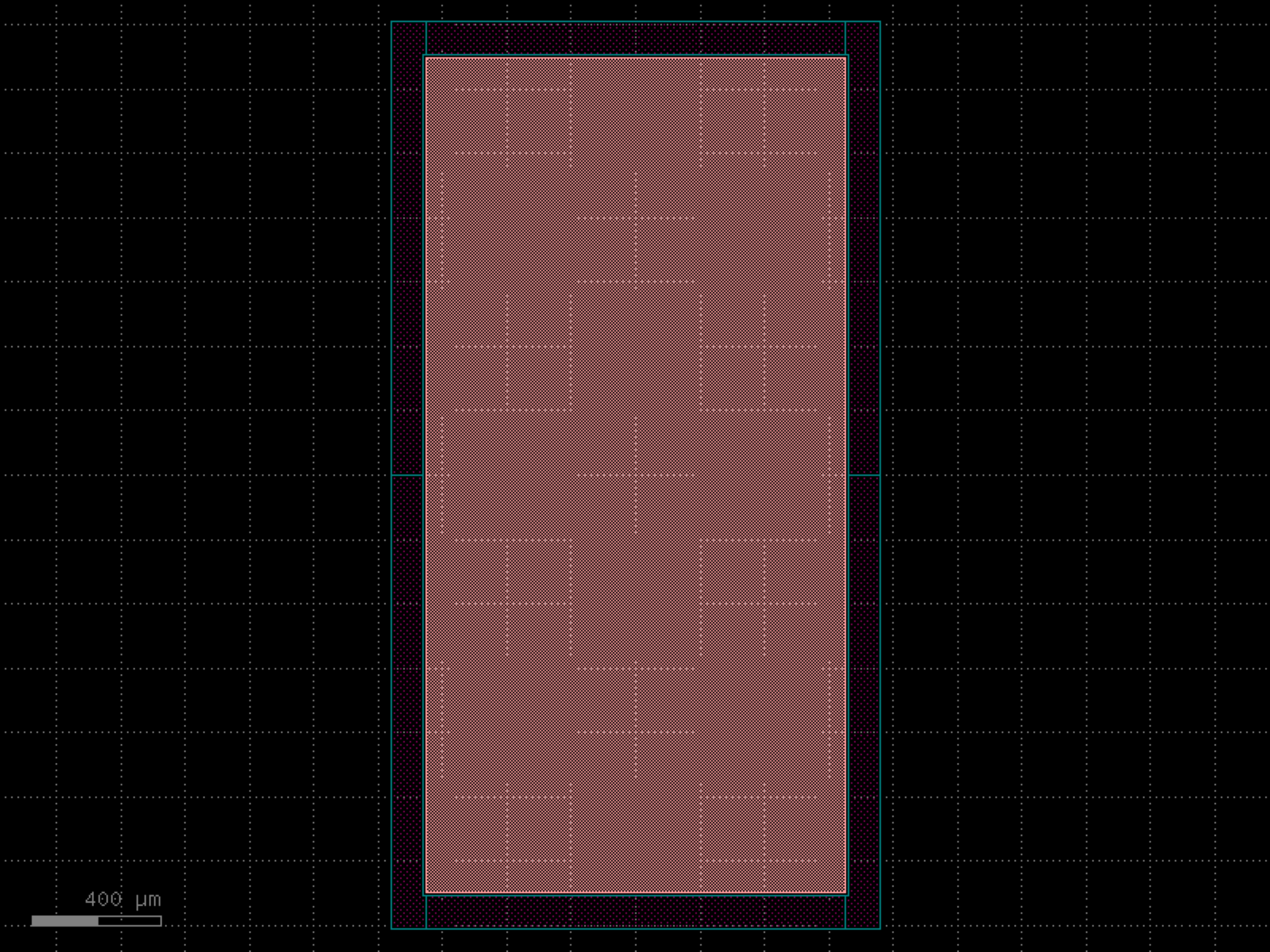

- gdsfactory.components.mems.bolometer(absorber_width=20.0, absorber_length=20.0, leg_width=0.5, leg_length=15.0, n_legs=4, pad_width=5.0, pad_length=5.0, layer='WG', port_type='electrical')[source]#
Returns a bolometer thermal detector.
A central absorber rectangle with thin L-shaped support legs extending outward to anchor pads distributed around the perimeter.
- Parameters:
absorber_width (float) – width of the central absorber.
absorber_length (float) – length of the central absorber.
leg_width (float) – width of each support leg.
leg_length (float) – length of each support leg.
n_legs (int) – number of support legs (distributed around perimeter).
pad_width (float) – width of each anchor pad.
pad_length (float) – length of each anchor pad.
layer (LayerSpec) – layer spec.
port_type (str) – port type for electrical ports.
- Return type:
import gdsfactory as gf

gf.gpdk.PDK.activate()

c = gf.components.bolometer(absorber_width=20, absorber_length=20, leg_width=0.5, leg_length=15, n_legs=4, pad_width=5, pad_length=5, layer='WG', port_type='electrical').copy()
c.draw_ports()
c.plot()
(Source code, png, hires.png, pdf)
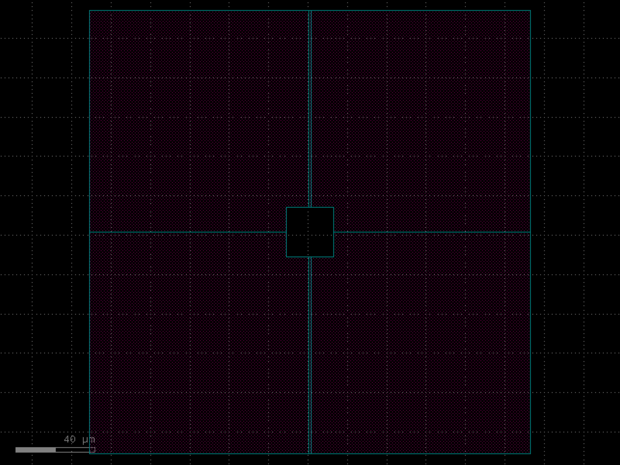
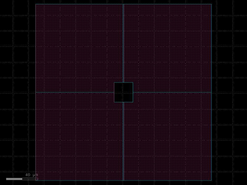
- gdsfactory.components.mems.cantilever(beam_width=2.0, beam_length=20.0, anchor_width=5.0, anchor_length=5.0, layer='WG', port_type='electrical')[source]#
Returns a simple cantilever beam with an anchor.
A rectangular anchor on the left with a thinner beam extending to the right.
- Parameters:
beam_width (float) – width of the cantilever beam.
beam_length (float) – length of the cantilever beam.
anchor_width (float) – width (vertical) of the anchor pad.
anchor_length (float) – length (horizontal) of the anchor pad.
layer (LayerSpec) – layer spec.
port_type (str) – port type for electrical ports.
- Return type:
import gdsfactory as gf

gf.gpdk.PDK.activate()

c = gf.components.cantilever(beam_width=2, beam_length=20, anchor_width=5, anchor_length=5, layer='WG', port_type='electrical').copy()
c.draw_ports()
c.plot()
(Source code, png, hires.png, pdf)
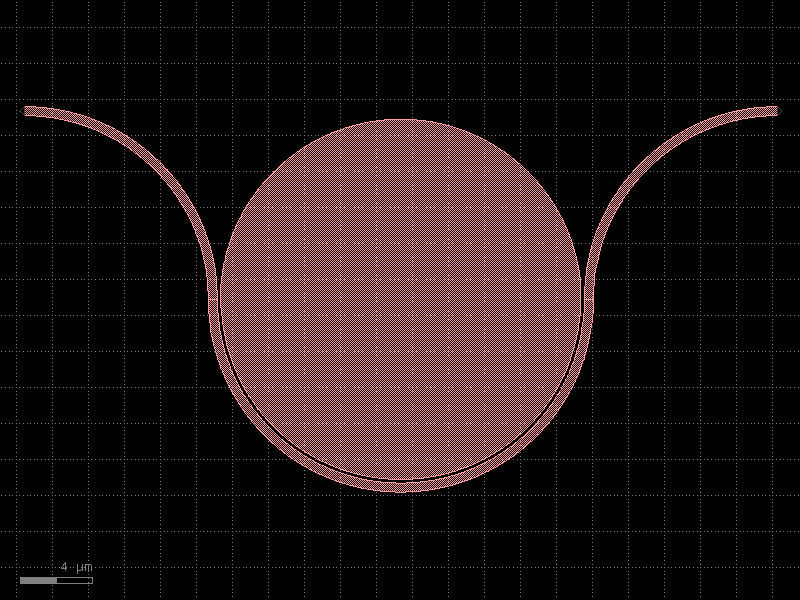
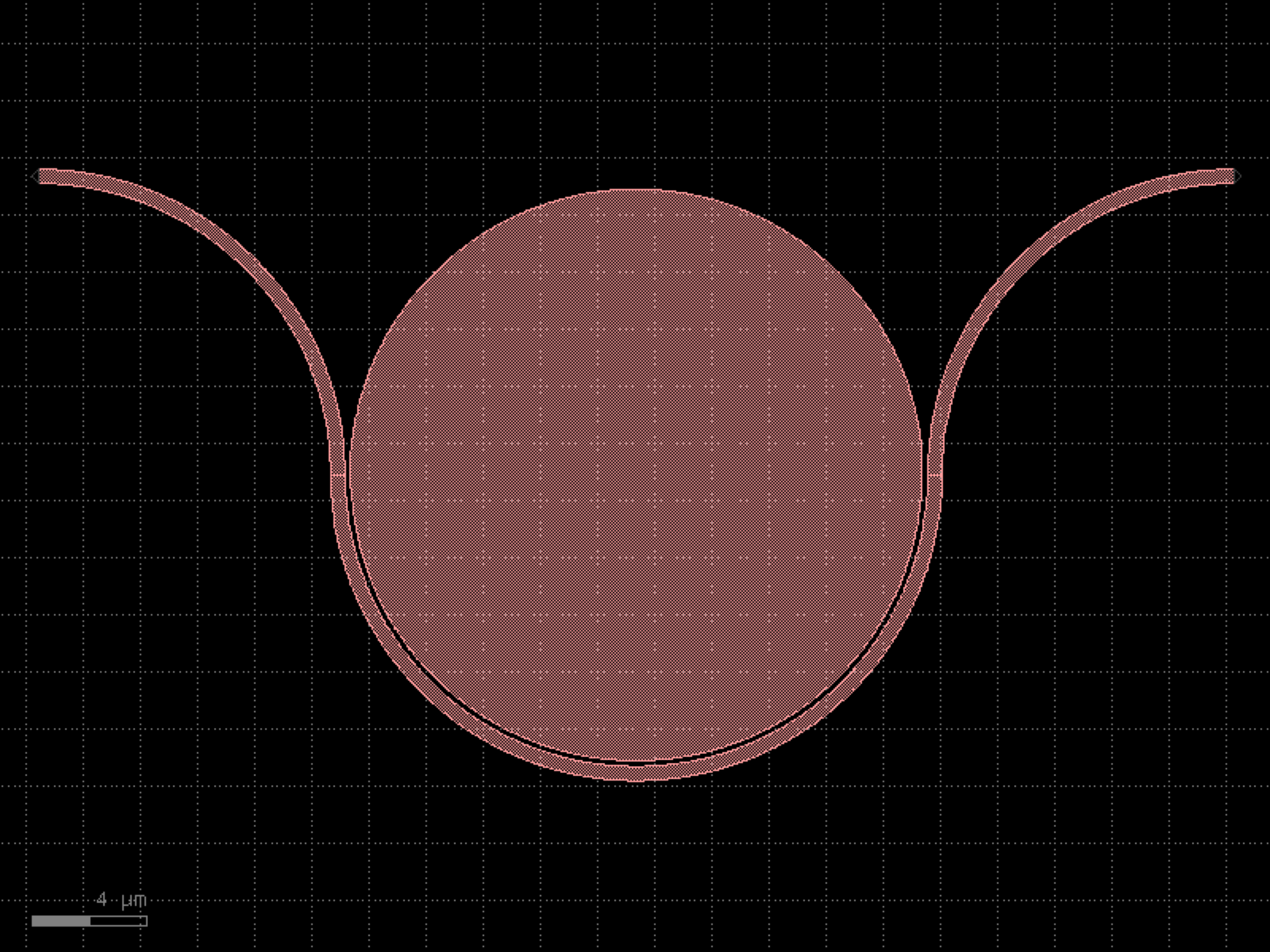

- gdsfactory.components.mems.comb_drive(finger_width=0.5, finger_length=10.0, finger_gap=0.5, n_fingers=20, finger_overlap=5.0, shuttle_width=5.0, shuttle_length=30.0, spring_width=0.5, spring_length=20.0, n_spring_folds=4, anchor_size=10.0, layer='WG')[source]#
Returns a comb drive actuator with interdigitated fingers and folded springs.
A central shuttle with comb fingers on both sides, fixed electrodes with interleaving fingers, and folded springs connecting the shuttle to corner anchor pads.
- Parameters:
finger_width (float) – width of each comb finger.
finger_length (float) – length of each comb finger.
finger_gap (float) – gap between adjacent moving and fixed fingers.
n_fingers (int) – number of moving fingers on each side.
finger_overlap (float) – overlap length between moving and fixed fingers in the actuation direction.
shuttle_width (float) – width (vertical) of the shuttle mass.
shuttle_length (float) – length (horizontal) of the shuttle mass.
spring_width (float) – width of spring beam segments.
spring_length (float) – length of each spring fold segment.
n_spring_folds (int) – number of folds in each folded spring.
anchor_size (float) – size of each square anchor pad.
layer (LayerSpec) – layer spec.
- Return type:
import gdsfactory as gf

gf.gpdk.PDK.activate()

c = gf.components.comb_drive(finger_width=0.5, finger_length=10, finger_gap=0.5, n_fingers=20, finger_overlap=5, shuttle_width=5, shuttle_length=30, spring_width=0.5, spring_length=20, n_spring_folds=4, anchor_size=10, layer='WG').copy()
c.draw_ports()
c.plot()
(Source code, png, hires.png, pdf)
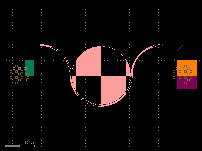
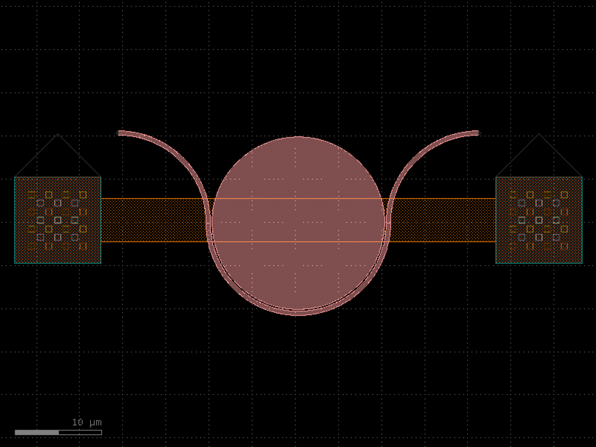

- gdsfactory.components.mems.doubly_clamped_beam(beam_width=1.0, beam_length=30.0, anchor_width=5.0, anchor_length=5.0, layer='WG', port_type='electrical')[source]#
Returns a doubly clamped beam fixed at both ends.
Two anchor pads connected by a thin beam, centered at the origin.
- Parameters:
beam_width (float) – width of the beam.
beam_length (float) – length of the beam between the two anchors.
anchor_width (float) – width (vertical) of each anchor pad.
anchor_length (float) – length (horizontal) of each anchor pad.
layer (LayerSpec) – layer spec.
port_type (str) – port type for electrical ports.
- Return type:
import gdsfactory as gf

gf.gpdk.PDK.activate()

c = gf.components.doubly_clamped_beam(beam_width=1, beam_length=30, anchor_width=5, anchor_length=5, layer='WG', port_type='electrical').copy()
c.draw_ports()
c.plot()
(Source code, png, hires.png, pdf)
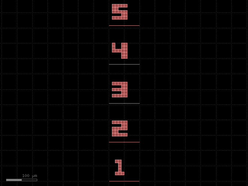

- gdsfactory.components.mems.folded_spring(beam_width=0.5, beam_length=20.0, n_folds=4, fold_gap=1.0, anchor_width=5.0, anchor_length=3.0, layer='WG', port_type='electrical')[source]#
Returns a folded flexure spring (serpentine meander).
Alternating horizontal beams connected at their ends forming a serpentine pattern. Starts at a bottom anchor and ends at a top anchor.
- Parameters:
beam_width (float) – width of each beam segment.
beam_length (float) – length of each horizontal beam segment.
n_folds (int) – number of horizontal beam segments.
fold_gap (float) – vertical gap between adjacent beams.
anchor_width (float) – width (horizontal) of the anchor pads.
anchor_length (float) – length (vertical) of the anchor pads.
layer (LayerSpec) – layer spec.
port_type (str) – port type for electrical ports.
- Return type:
import gdsfactory as gf

gf.gpdk.PDK.activate()

c = gf.components.folded_spring(beam_width=0.5, beam_length=20, n_folds=4, fold_gap=1, anchor_width=5, anchor_length=3, layer='WG', port_type='electrical').copy()
c.draw_ports()
c.plot()
(Source code, png, hires.png, pdf)
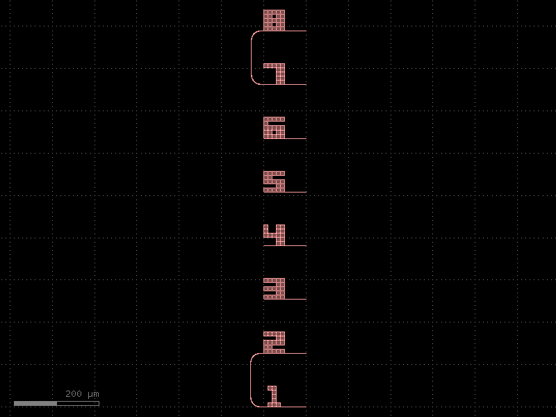
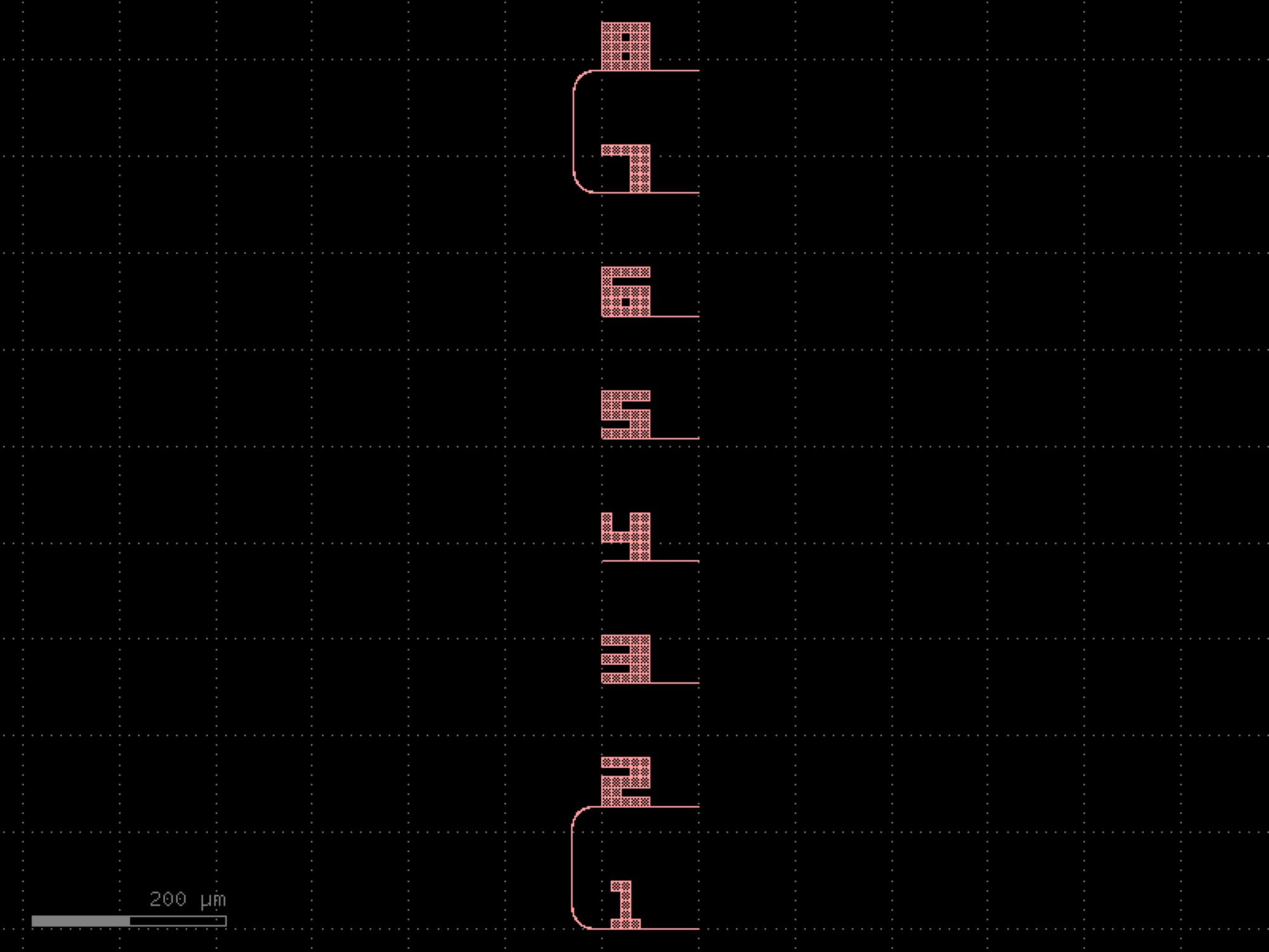

- gdsfactory.components.mems.gear(n_teeth=20, module_size=2.0, pressure_angle=20.0, hub_radius=None, hub_hole_radius=0.0, layer='WG')[source]#
Returns a gear with simplified trapezoidal teeth.
- Parameters:
n_teeth (int) – number of teeth.
module_size (float) – gear module (pitch diameter / number of teeth).
pressure_angle (float) – pressure angle in degrees.
hub_radius (float | None) – radius of the central hub disc. Defaults to root_radius * 0.6.
hub_hole_radius (float) – radius of a center hole (0 to disable).
layer (LayerSpec) – layer spec.
- Return type:
import gdsfactory as gf

gf.gpdk.PDK.activate()

c = gf.components.gear(n_teeth=20, module_size=2, pressure_angle=20, hub_hole_radius=0, layer='WG').copy()
c.draw_ports()
c.plot()
(Source code, png, hires.png, pdf)
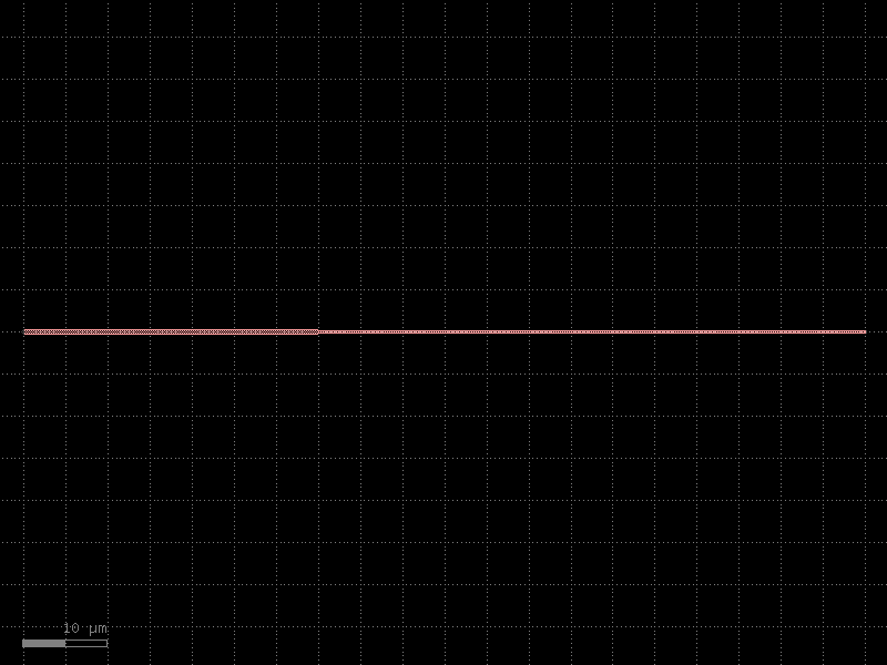
microfluidics#
- gdsfactory.components.microfluidics.arrow_junction(main_width=1.0, branch_width=1.0, main_length=20.0, branch_length=10.0, branch_angle=35.0, reservoir_radius=0.0, n_reservoir_points=64, layer='WG', port_type='optical')[source]#
Returns a microfluidic arrow (Y) junction.
A main horizontal channel on the right side with two angled branches diverging to the left at +/- branch_angle from horizontal. The junction point is at the origin.
- Parameters:
main_width (float) – width of the main horizontal channel.
branch_width (float) – width of each angled branch channel.
main_length (float) – length of the main channel (extends to the right).
branch_length (float) – length of each angled branch.
branch_angle (float) – angle of each branch from horizontal (degrees).
reservoir_radius (float) – radius of circular reservoirs at endpoints (0 to disable).
n_reservoir_points (int) – number of polygon points for reservoir circles.
layer (LayerSpec) – layer spec.
port_type (str | None) – None, optical, or electrical.
- Return type:
import gdsfactory as gf

gf.gpdk.PDK.activate()

c = gf.components.arrow_junction(main_width=1, branch_width=1, main_length=20, branch_length=10, branch_angle=35, reservoir_radius=0, n_reservoir_points=64, layer='WG', port_type='optical').copy()
c.draw_ports()
c.plot()
(Source code, png, hires.png, pdf)
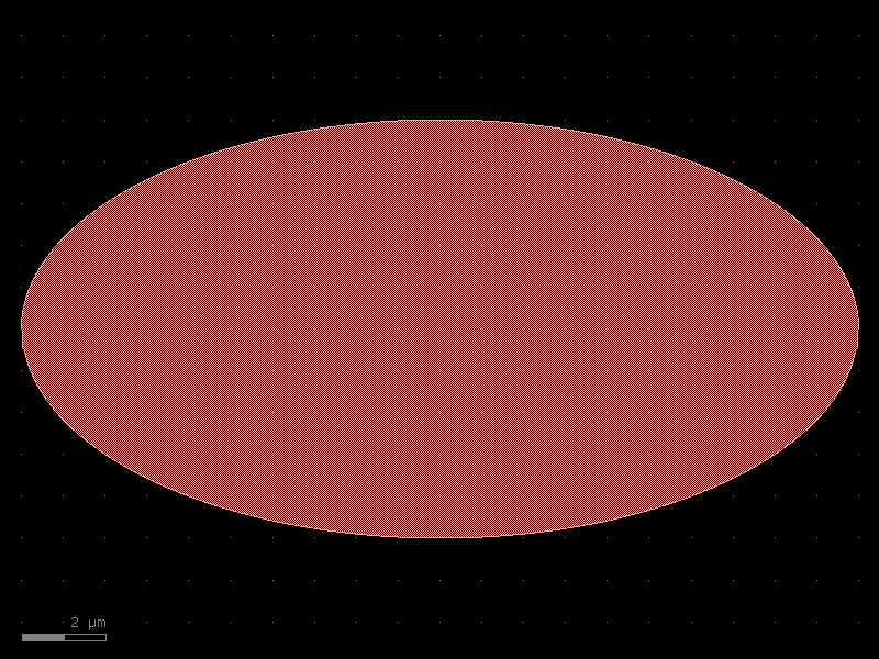
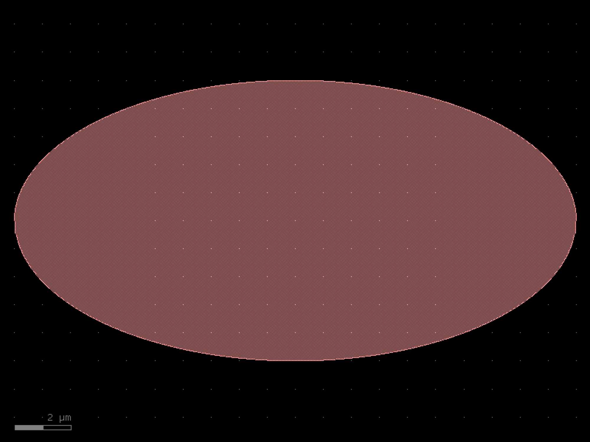

- gdsfactory.components.microfluidics.h_junction(main_width=1.0, branch_width=1.0, main_length=20.0, branch_length=10.0, reservoir_radius=0.0, n_reservoir_points=64, layer='WG', port_type='optical')[source]#
Returns a microfluidic H-junction.
A horizontal main channel with two vertical branches extending up and down from the center. Optionally adds circular reservoirs at the four endpoints.
- Parameters:
main_width (float) – width of the main horizontal channel.
branch_width (float) – width of the vertical branch channels.
main_length (float) – total length of the main channel.
branch_length (float) – length of each vertical branch.
reservoir_radius (float) – radius of circular reservoirs at endpoints (0 to disable).
n_reservoir_points (int) – number of polygon points for reservoir circles.
layer (LayerSpec) – layer spec.
port_type (str | None) – None, optical, or electrical.
- Return type:
import gdsfactory as gf

gf.gpdk.PDK.activate()

c = gf.components.h_junction(main_width=1, branch_width=1, main_length=20, branch_length=10, reservoir_radius=0, n_reservoir_points=64, layer='WG', port_type='optical').copy()
c.draw_ports()
c.plot()
(Source code, png, hires.png, pdf)
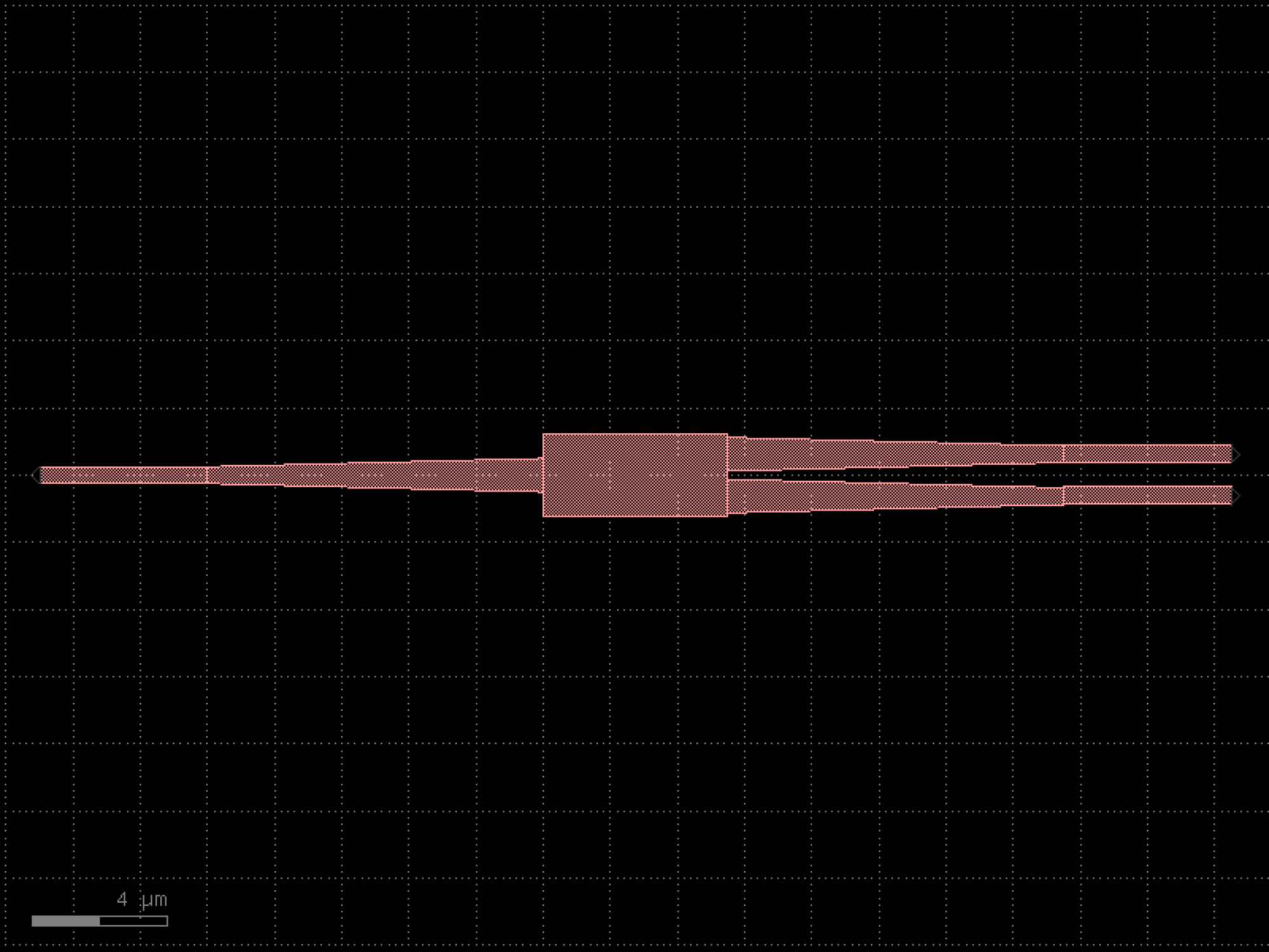
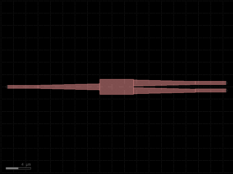
- gdsfactory.components.microfluidics.meander_channel(channel_width=1.0, n_turns=5, turn_spacing=5.0, straight_length=20.0, reservoir_length=5.0, reservoir_height=5.0, layer='WG', port_type='optical')[source]#
Returns a microfluidic meander (serpentine) channel.
Builds a series of connected rectangles forming a serpentine path. Starts from the left, goes right for straight_length, turns up/down by turn_spacing, goes back left, and repeats for n_turns. Rectangular reservoirs are added at the inlet and outlet when reservoir_length > 0.
- Parameters:
channel_width (float) – width of the channel.
n_turns (int) – number of straight segments (horizontal passes).
turn_spacing (float) – center-to-center vertical spacing between passes.
straight_length (float) – length of each horizontal segment.
reservoir_length (float) – length of the reservoirs at inlet/outlet.
reservoir_height (float) – height of the reservoirs at inlet/outlet.
layer (LayerSpec) – layer spec.
port_type (str | None) – None, optical, or electrical.
- Return type:
import gdsfactory as gf

gf.gpdk.PDK.activate()

c = gf.components.meander_channel(channel_width=1, n_turns=5, turn_spacing=5, straight_length=20, reservoir_length=5, reservoir_height=5, layer='WG', port_type='optical').copy()
c.draw_ports()
c.plot()
(Source code, png, hires.png, pdf)
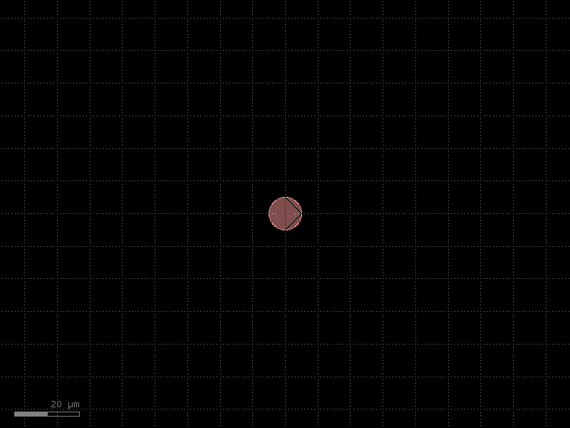
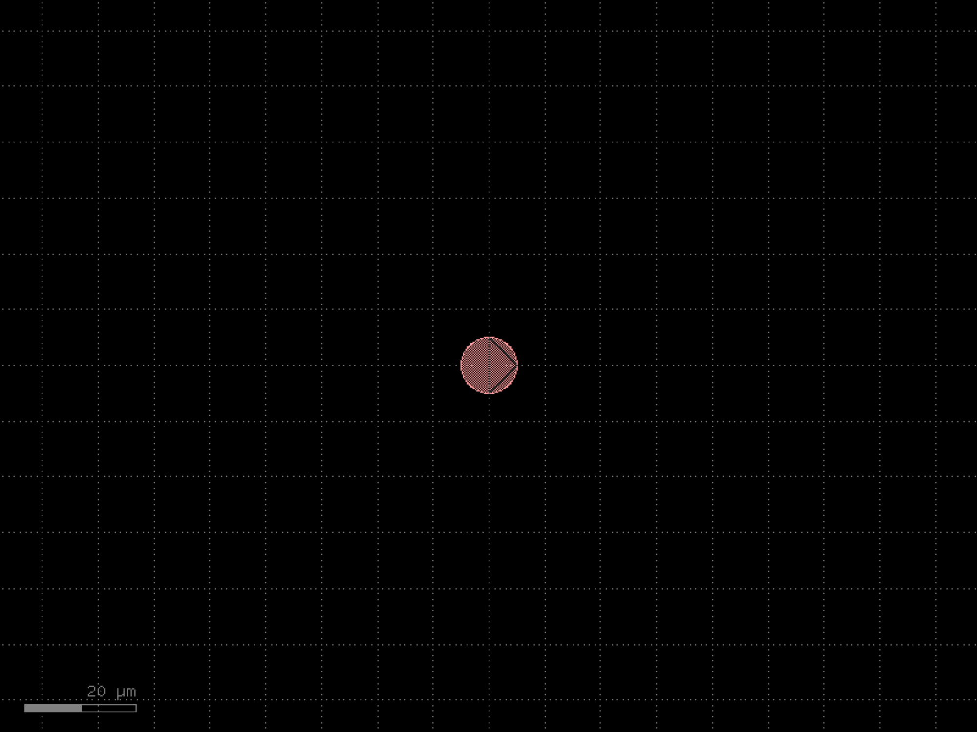

- gdsfactory.components.microfluidics.t_junction(main_width=1.0, branch_width=1.0, main_length=20.0, branch_length=10.0, reservoir_radius=0.0, n_reservoir_points=64, layer='WG', port_type='optical')[source]#
Returns a microfluidic T-junction.
A horizontal main channel with a vertical branch going up from the center. Optionally adds circular reservoirs at the three endpoints.
- Parameters:
main_width (float) – width of the main horizontal channel.
branch_width (float) – width of the vertical branch channel.
main_length (float) – total length of the main channel.
branch_length (float) – length of the vertical branch.
reservoir_radius (float) – radius of circular reservoirs at endpoints (0 to disable).
n_reservoir_points (int) – number of polygon points for reservoir circles.
layer (LayerSpec) – layer spec.
port_type (str | None) – None, optical, or electrical.
- Return type:
import gdsfactory as gf

gf.gpdk.PDK.activate()

c = gf.components.t_junction(main_width=1, branch_width=1, main_length=20, branch_length=10, reservoir_radius=0, n_reservoir_points=64, layer='WG', port_type='optical').copy()
c.draw_ports()
c.plot()
(Source code, png, hires.png, pdf)
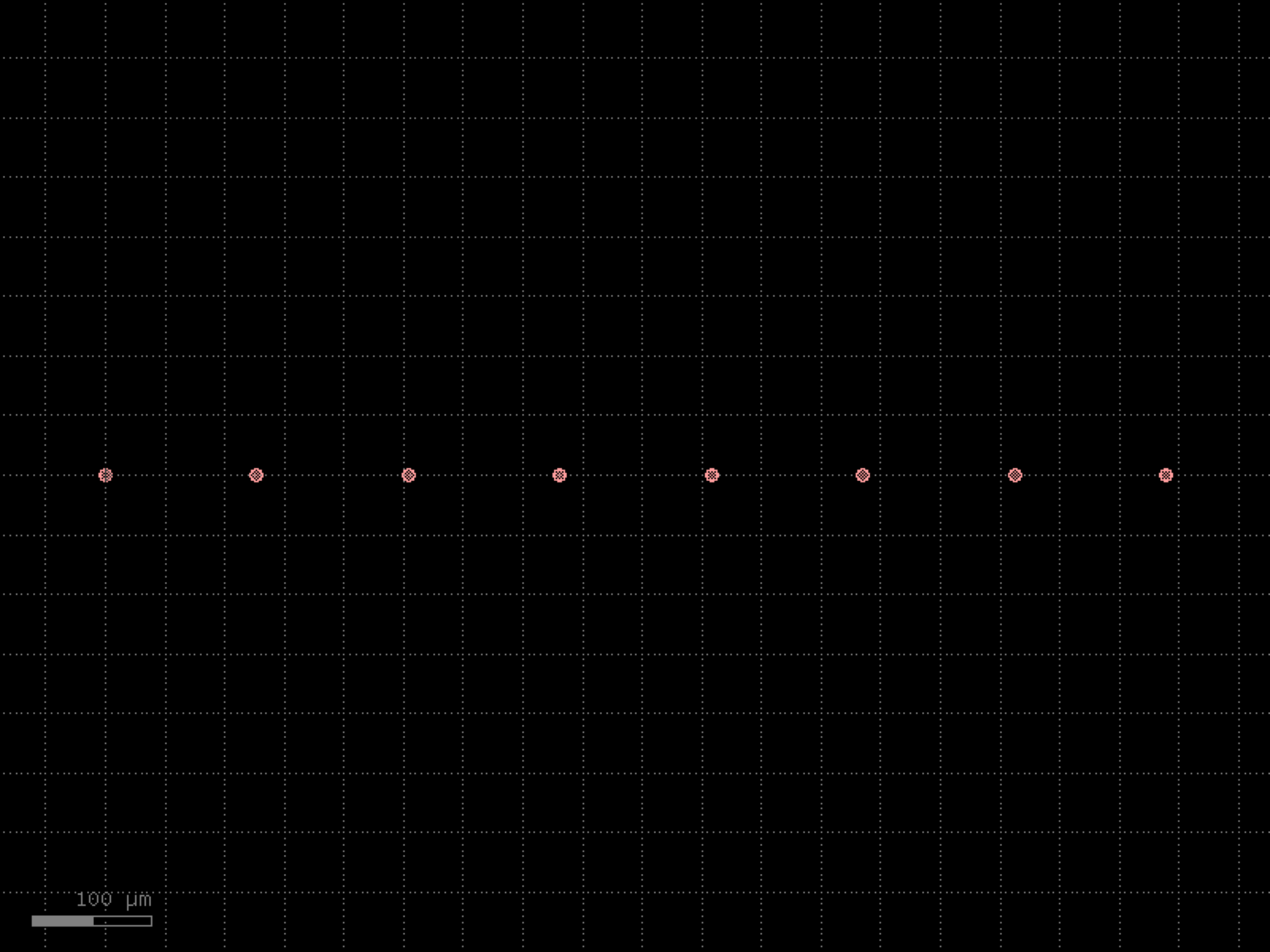
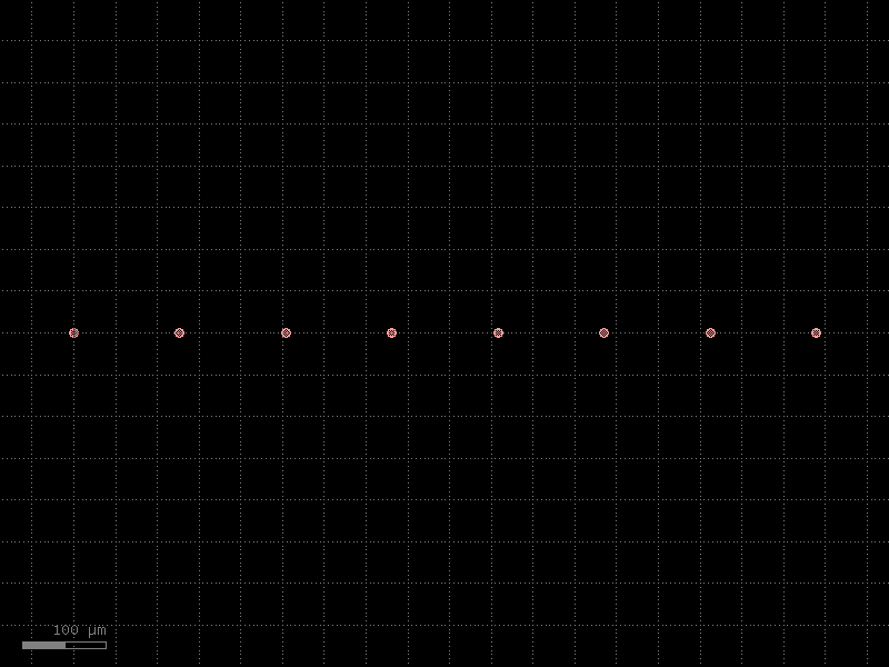
mmis#
- gdsfactory.components.mmis.mmi(inputs=1, outputs=4, width=None, width_taper=1.0, length_taper=10.0, length_mmi=5.5, width_mmi=5, gap_input_tapers=0.25, gap_output_tapers=0.25, taper='taper', straight='straight', cross_section='strip', input_positions=None, output_positions=None)[source]#
Mxn MultiMode Interferometer (MMI).
- Parameters:
inputs (int) – number of inputs.
outputs (int) – number of outputs.
width (float | None) – input and output straight width. Defaults to cross_section.
width_taper (float) – interface between input straights and mmi region.
length_taper (float) – into the mmi region.
length_mmi (float) – in x direction.
width_mmi (float) – in y direction.
gap_input_tapers (float) – gap between input tapers from edge to edge.
gap_output_tapers (float) – gap between output tapers from edge to edge.
taper (ComponentSpec) – taper function.
straight (ComponentSpec) – straight function.
cross_section (CrossSectionSpec) – specification (CrossSection, string or dict).
input_positions (list[float] | None) – optional positions of the inputs.
output_positions (list[float] | None) – optional positions of the outputs.
- Return type:
       length_mmi
        <------>
        ________
       |        |
    __/          \__
o2  __            __  o3
      \          /_ _ _ _
      |         | _ _ _ _| gap_output_tapers
    __/          \__
o1  __            __  o4
      \          /
       |________|
     | |
     <->
length_taper
import gdsfactory as gf

gf.gpdk.PDK.activate()

c = gf.components.mmi(inputs=1, outputs=4, width_taper=1, length_taper=10, length_mmi=5.5, width_mmi=5, gap_input_tapers=0.25, gap_output_tapers=0.25, taper='taper', straight='straight', cross_section='strip').copy()
c.draw_ports()
c.plot()
(Source code, png, hires.png, pdf)
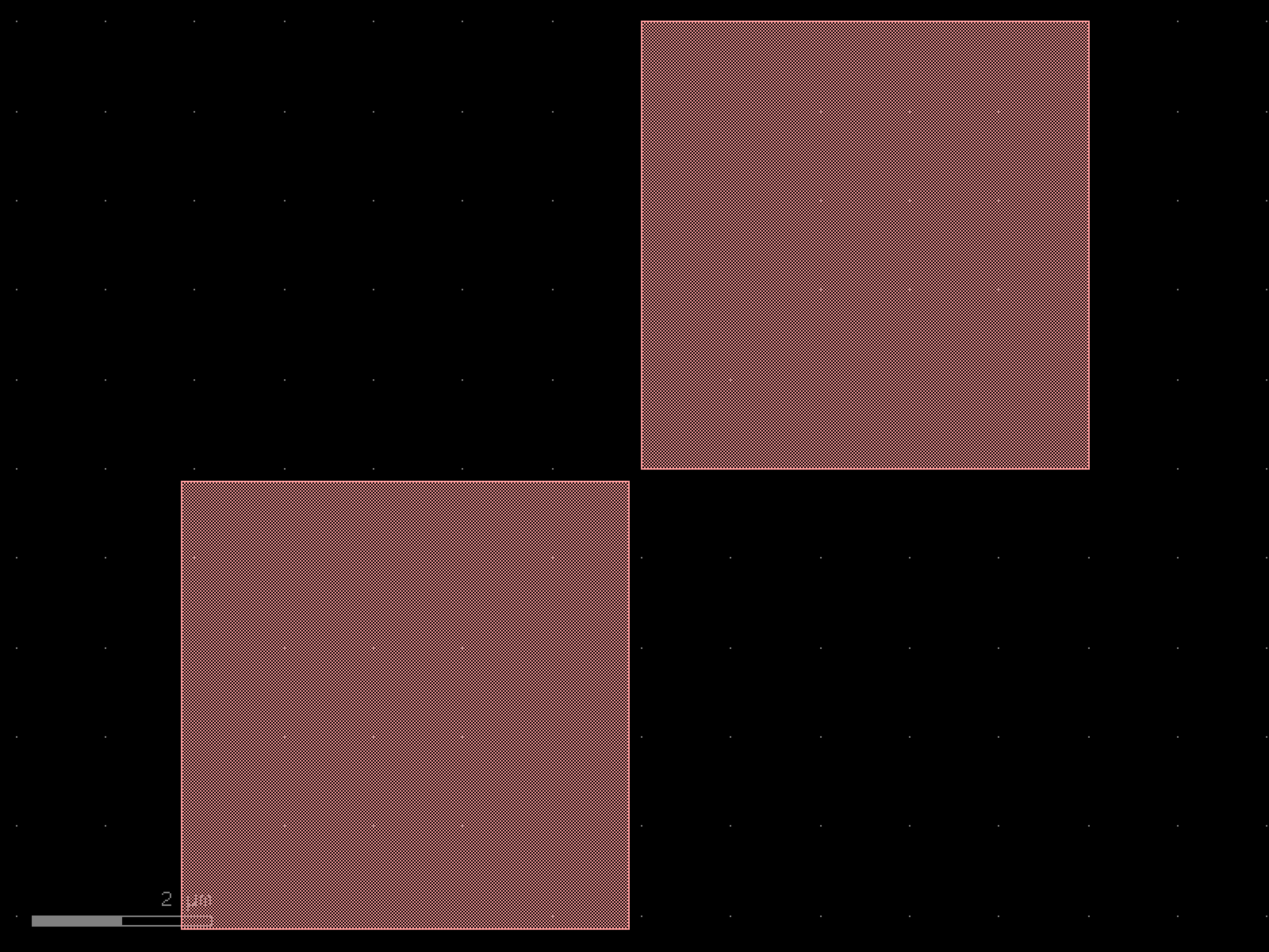
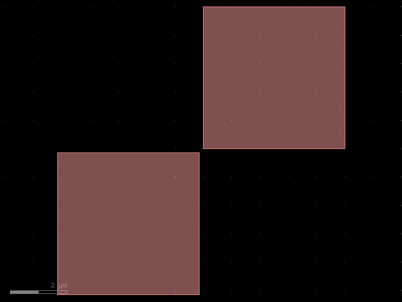
- gdsfactory.components.mmis.mmi1x2(width=None, width_taper=1.0, length_taper=10.0, length_mmi=5.5, width_mmi=2.5, gap_mmi=0.25, taper=<function taper>, straight=<function straight>, cross_section='strip')[source]#
1x2 MultiMode Interferometer (MMI).
- Parameters:
width (float | None) – input and output straight width. Defaults to cross_section width.
width_taper (float) – interface between input straights and mmi region.
length_taper (float) – into the mmi region.
length_mmi (float) – in x direction.
width_mmi (float) – in y direction.
gap_mmi (float) – gap between tapered wg.
taper (ComponentSpec) – taper function.
straight (ComponentSpec) – straight function.
cross_section (CrossSectionSpec) – specification (CrossSection, string or dict).
- Return type:
       length_mmi
        <------>
        ________
       |        |
       |         \__
       |          __  o2
    __/          /_ _ _ _
 o1 __          | _ _ _ _| gap_mmi
      \          \__
       |          __  o3
       |         /
       |________|

     <->
length_taper
import gdsfactory as gf

gf.gpdk.PDK.activate()

c = gf.components.mmi1x2(width_taper=1, length_taper=10, length_mmi=5.5, width_mmi=2.5, gap_mmi=0.25, cross_section='strip').copy()
c.draw_ports()
c.plot()
(Source code, png, hires.png, pdf)
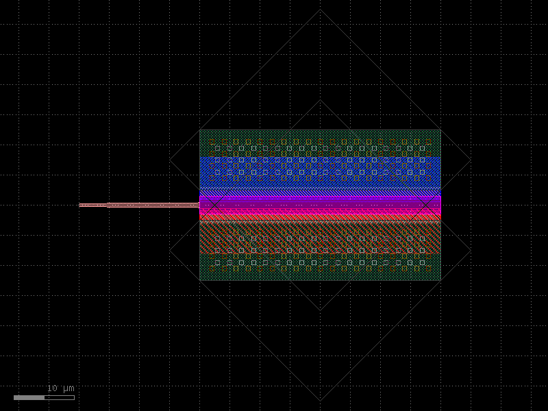

- gdsfactory.components.mmis.mmi1x2_with_sbend(with_sbend=True, s_bend=<function bend_s>, cross_section='strip')[source]#
Returns 1x2 splitter for Cband.
https://opg.optica.org/oe/fulltext.cfm?uri=oe-21-1-1310&id=248418
- Parameters:
with_sbend (bool) – add sbend.
s_bend (Callable[[...], Component]) – S-bend spec.
cross_section (CrossSection | str | dict[str, Any] | Callable[[...], CrossSection] | SymmetricalCrossSection | DCrossSection) – spec.
- Return type:
import gdsfactory as gf

gf.gpdk.PDK.activate()

c = gf.components.mmi1x2_with_sbend(with_sbend=True, cross_section='strip').copy()
c.draw_ports()
c.plot()
(Source code, png, hires.png, pdf)
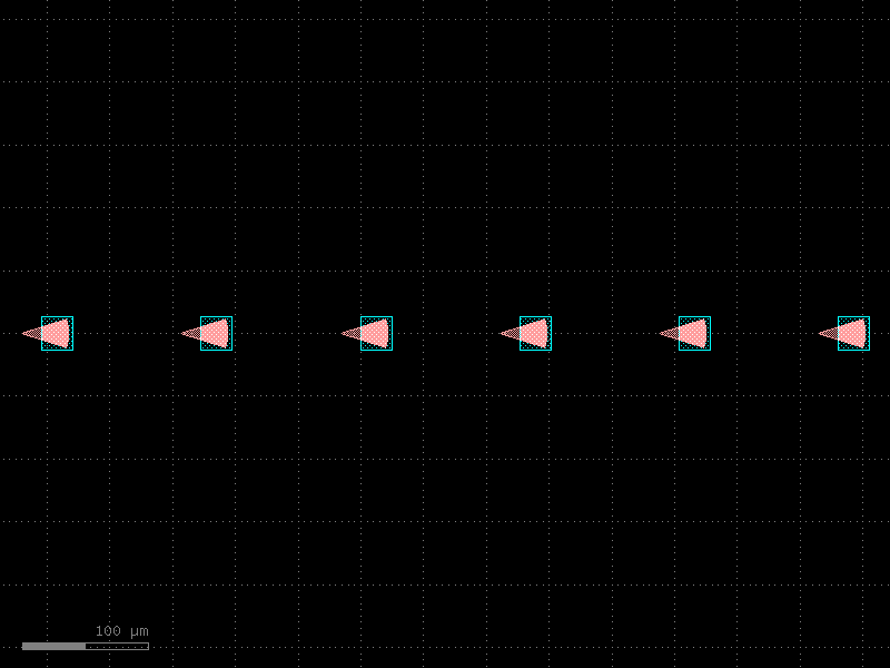
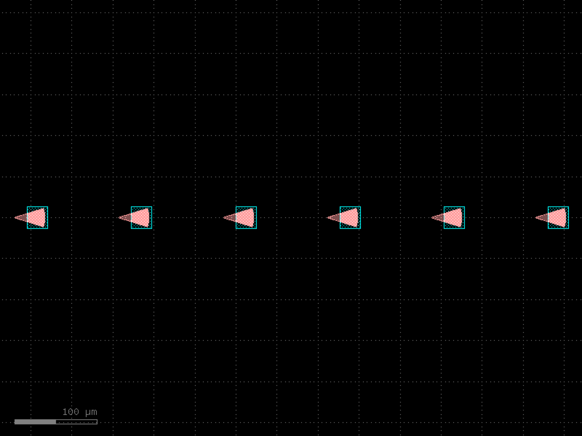

- gdsfactory.components.mmis.mmi2x2(width=None, width_taper=1.0, length_taper=10.0, length_mmi=5.5, width_mmi=2.5, gap_mmi=0.25, taper=<function taper>, straight=<function straight>, cross_section='strip')[source]#
Mmi 2x2.
- Parameters:
width (float | None) – input and output straight width.
width_taper (float) – interface between input straights and mmi region.
length_taper (float) – into the mmi region.
length_mmi (float) – in x direction.
width_mmi (float) – in y direction.
gap_mmi (float) – (width_taper + gap between tapered wg)/2.
taper (ComponentSpec) – taper function.
straight (ComponentSpec) – straight function.
cross_section (CrossSectionSpec) – spec.
- Return type:
       length_mmi
        <------>
        ________
       |        |
    __/          \__
o2  __            __  o3
      \          /_ _ _ _
      |         | _ _ _ _| gap_mmi
    __/          \__
o1  __            __  o4
      \          /
       |________|

     <->
length_taper
import gdsfactory as gf

gf.gpdk.PDK.activate()

c = gf.components.mmi2x2(width_taper=1, length_taper=10, length_mmi=5.5, width_mmi=2.5, gap_mmi=0.25, cross_section='strip').copy()
c.draw_ports()
c.plot()
(Source code, png, hires.png, pdf)
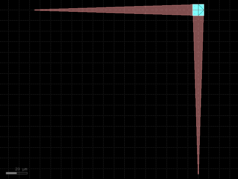
- gdsfactory.components.mmis.mmi2x2_with_sbend(with_sbend=True, s_bend=<function bend_s>, cross_section='strip')[source]#
Returns mmi2x2 for Cband.
C_band 2x2MMI in 220nm thick silicon https://opg.optica.org/oe/fulltext.cfm?uri=oe-25-23-28957&id=376719
- Parameters:
with_sbend (bool) – add sbend.
s_bend (Callable[[...], Component]) – S-bend function.
cross_section (CrossSection | str | dict[str, Any] | Callable[[...], CrossSection] | SymmetricalCrossSection | DCrossSection) – spec.
- Return type:
import gdsfactory as gf

gf.gpdk.PDK.activate()

c = gf.components.mmi2x2_with_sbend(with_sbend=True, cross_section='strip').copy()
c.draw_ports()
c.plot()
(Source code, png, hires.png, pdf)
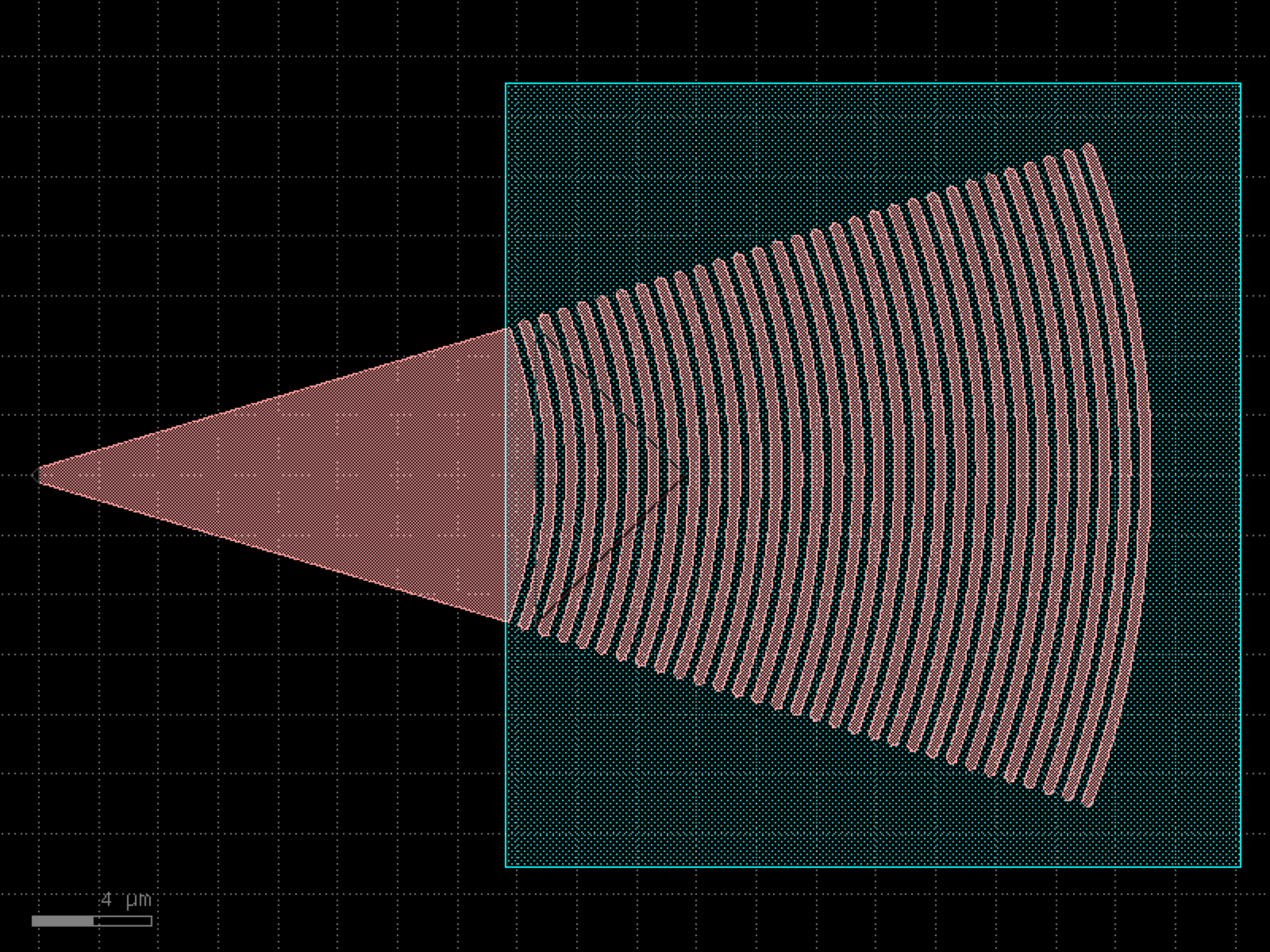
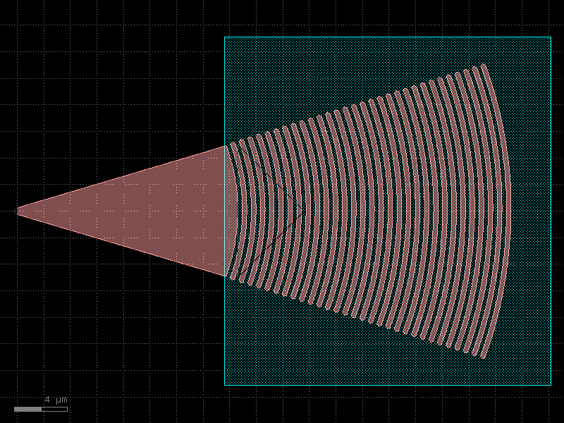
- gdsfactory.components.mmis.mmi_90degree_hybrid(width=0.5, width_taper=1.7, length_taper=40.0, length_mmi=175.0, width_mmi=10.0, gap_mmi=0.8, straight='straight', cross_section='strip')[source]#
90 degree hybrid based on a 4x4 MMI.
Default values from Watanabe et al., “Coherent few mode demultiplexer realized as a 2D grating coupler array in silicon”, Optics Express 28(24), 2020
It could be interesting to consider the design in Guan et al., “Compact and low loss 90° optical hybrid on a silicon-on-insulator platform”, Optics Express 25(23), 2017
- Parameters:
width (float) – input and output straight width.
width_taper (float) – interface between input straights and mmi region.
length_taper (float) – into the mmi region.
length_mmi (float) – in x direction.
width_mmi (float) – in y direction.
gap_mmi (float) – (width_taper + gap between tapered wg)/2.
straight (ComponentSpec) – straight function.
with_bbox – box in bbox_layers and bbox_offsets avoid DRC sharp edges.
cross_section (CrossSectionSpec) – spec.
- Return type:
              length_mmi
               <------>
               ________
              |        |
           __/          \__
signal_in  __            __  I_out1
             \          /_ _ _ _
             |         | _ _ _ _| gap_mmi
             |          \__
             |           __  Q_out1
             |          /
             |        |
             |
           __/          \__
   LO_in   __            __  Q_out2
             \          /_ _ _ _
             |         | _ _ _ _| gap_mmi
             |          \__
             |           __  I_out2
             |          /
             | ________|


            <->
       length_taper
import gdsfactory as gf

gf.gpdk.PDK.activate()

c = gf.components.mmi_90degree_hybrid(width=0.5, width_taper=1.7, length_taper=40, length_mmi=175, width_mmi=10, gap_mmi=0.8, straight='straight', cross_section='strip').copy()
c.draw_ports()
c.plot()
(Source code, png, hires.png, pdf)
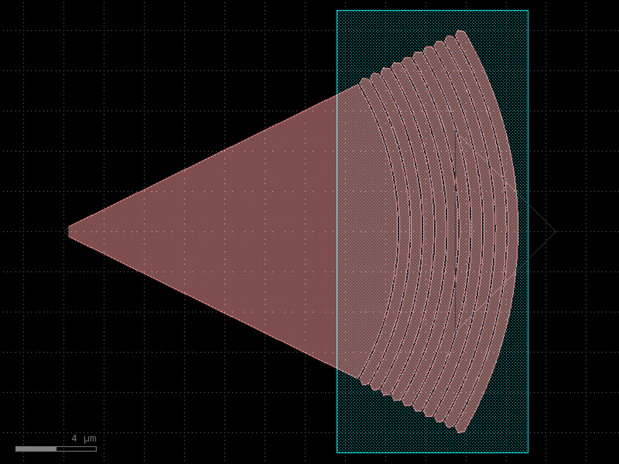
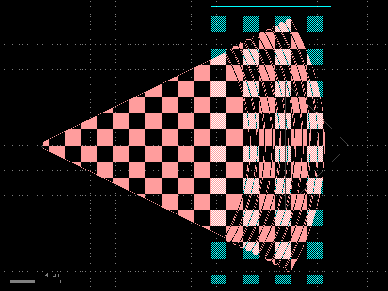
- gdsfactory.components.mmis.mmi_tapered(inputs=1, outputs=2, width=None, width_taper_in=2.0, length_taper_in=1.0, width_taper_out=None, length_taper_out=None, width_taper=1.0, length_taper=10.0, length_taper_start=None, length_taper_end=None, length_mmi=5.5, width_mmi=5, width_mmi_inner=None, gap_input_tapers=0.25, gap_output_tapers=0.25, taper=<function taper>, cross_section='strip', input_positions=None, output_positions=None)[source]#
Mxn MultiMode Interferometer (MMI).
This is jut a more general version of the mmi component. Make sure you simulate and optimize the component before using it.
- Parameters:
inputs (int) – number of inputs.
outputs (int) – number of outputs.
width (float | None) – input and output straight width. Defaults to cross_section.
width_taper_in (float) – interface between input straights and mmi region.
length_taper_in (float) – into the mmi region.
width_taper_out (float | None) – interface between mmi region and output straights.
length_taper_out (float | None) – into the mmi region.
width_taper (float) – interface between mmi region and output straights.
length_taper (float) – into the mmi region.
length_taper_start (float | None) – length of the taper at the start. Defaults to length_taper.
length_taper_end (float | None) – length of the taper at the end. Defaults to length_taper.
length_mmi (float) – in x direction.
width_mmi (float) – in y direction.
width_mmi_inner (float | None) – allows adding a different width for the inner mmi region.
gap_input_tapers (float) – gap between input tapers from edge to edge.
gap_output_tapers (float) – gap between output tapers from edge to edge.
taper (ComponentFactory) – taper function.
cross_section (CrossSectionSpec) – specification (CrossSection, string or dict).
input_positions (list[float] | None) – optional positions of the inputs.
output_positions (list[float] | None) – optional positions of the outputs.
- Return type:
                               ┌───────────┐
                               │           ├───────────────┐
                               │           │               ├────────────┐
       width_taper             │           │               │            │
            ▲ ┌────────────────┤           │               ├────────────┘
            │ │                │           ├───────────────┘
┌───────────┼─┤                │           │
│           │ │                │           │
◄───────────┼─►                │           ├───────────────┐
└───────────┼─┐                │           │               ├─────────────┐
            ▼ └────────────────┤           │               │             │
              ◄───────────────►│           │               ├─────────────┘
length_taper    length_taper_in│           ├───────────────┘ length_taper
◄────────────►                 └───────────┘◄────────────►  ◄────────────►
    start                                  length_taper_out      end
                               ◄───────────►
                                length_mmi
import gdsfactory as gf

gf.gpdk.PDK.activate()

c = gf.components.mmi_tapered(inputs=1, outputs=2, width_taper_in=2, length_taper_in=1, width_taper=1, length_taper=10, length_mmi=5.5, width_mmi=5, gap_input_tapers=0.25, gap_output_tapers=0.25, cross_section='strip').copy()
c.draw_ports()
c.plot()
(Source code, png, hires.png, pdf)
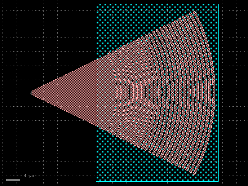
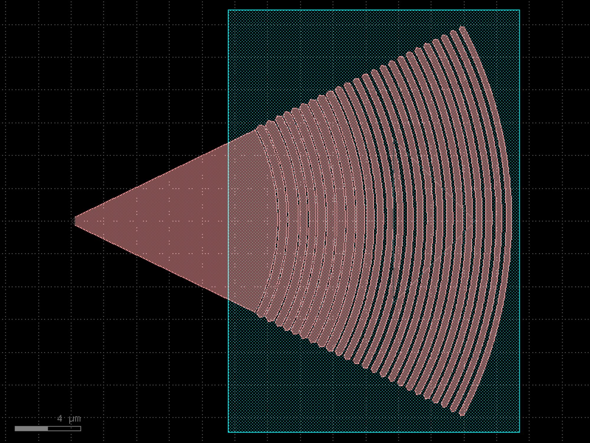

mzis#
- gdsfactory.components.mzis.mzi(delta_length=10.0, length_y=2.0, length_x=0.1, bend='bend_euler', straight='straight', straight_y=None, straight_x_top=None, straight_x_bot=None, splitter='mmi1x2', combiner=None, with_splitter=True, port_e1_splitter='o2', port_e0_splitter='o3', port_e1_combiner='o2', port_e0_combiner='o3', port1='o1', port2='o2', nbends=2, cross_section='strip', cross_section_x_top=None, cross_section_x_bot=None, mirror_bot=False, add_optical_ports_arms=False, min_length=0.01, auto_rename_ports=True, auto_detect_port_names=False)[source]#
Mzi.
- Parameters:
delta_length (float) – bottom arm vertical extra length.
length_y (float) – vertical length for both and top arms.
length_x (float | None) – horizontal length. None uses to the straight_x_bot/top defaults.
bend (ComponentSpec) – 90 degrees bend library.
straight (ComponentSpec) – straight function.
straight_y (ComponentSpec | None) – straight for length_y and delta_length.
straight_x_top (ComponentSpec | None) – top straight for length_x.
straight_x_bot (ComponentSpec | None) – bottom straight for length_x.
splitter (ComponentSpec) – splitter function.
combiner (ComponentSpec | None) – combiner function.
with_splitter (bool) – if False removes splitter.
port_e1_splitter (str) – east top splitter port.
port_e0_splitter (str) – east bot splitter port.
port_e1_combiner (str) – east top combiner port.
port_e0_combiner (str) – east bot combiner port.
port1 (str) – input port name.
port2 (str) – output port name.
nbends (int) – from straight top/bot to combiner (at least 2).
cross_section (CrossSectionSpec) – for routing (sxtop/sxbot to combiner).
cross_section_x_top (CrossSectionSpec | None) – optional top cross_section (defaults to cross_section).
cross_section_x_bot (CrossSectionSpec | None) – optional bottom cross_section (defaults to cross_section).
mirror_bot (bool) – if true, mirrors the bottom arm.
add_optical_ports_arms (bool) – add all other optical ports in the arms with top\_ and bot\_ prefix.
min_length (float) – minimum length for the straight.
auto_rename_ports (bool) – if True, renames ports.
auto_detect_port_names (bool) – whether to auto detect ports names. Ignores port_e* arguments if True.
- Return type:
               b2______b3
              |  sxtop  |
      straight_y        |
              |         |
              b1        b4
    splitter==|         |==combiner
              b5        b8
              |         |
      straight_y        |
              |         |
delta_length/2          |
              |         |
             b6__sxbot__b7
                  Lx
import gdsfactory as gf

gf.gpdk.PDK.activate()

c = gf.components.mzi(delta_length=10, length_y=2, length_x=0.1, bend='bend_euler', straight='straight', splitter='mmi1x2', with_splitter=True, port_e1_splitter='o2', port_e0_splitter='o3', port_e1_combiner='o2', port_e0_combiner='o3', port1='o1', port2='o2', nbends=2, cross_section='strip', mirror_bot=False, add_optical_ports_arms=False, min_length=0.01, auto_rename_ports=True, auto_detect_port_names=False).copy()
c.draw_ports()
c.plot()
(Source code, png, hires.png, pdf)
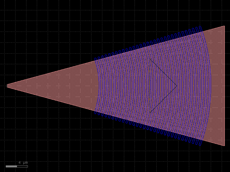
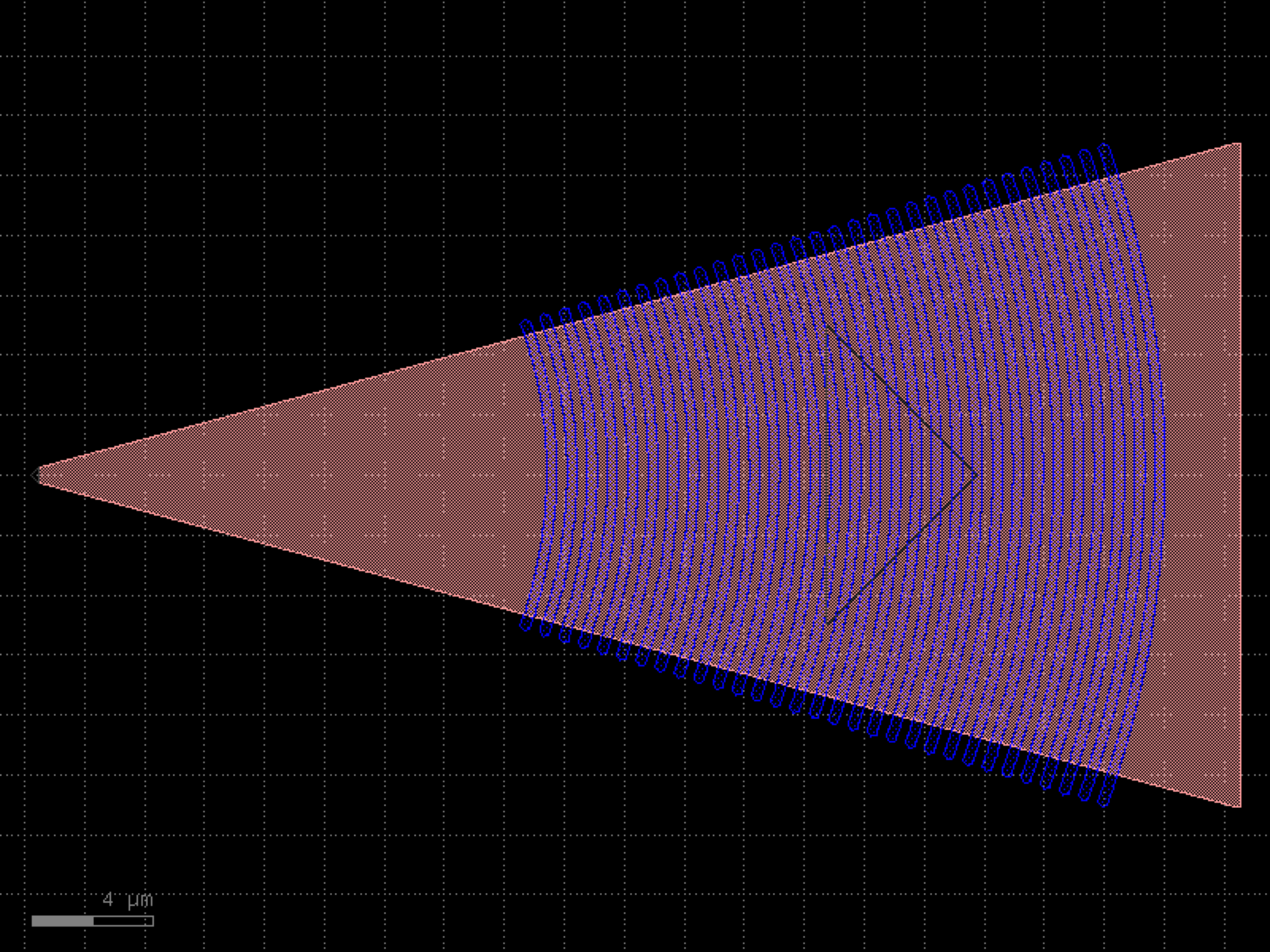

- gdsfactory.components.mzis.mzi1x2_2x2(delta_length=10.0, length_y=2.0, length_x=0.1, bend='bend_euler', straight='straight', straight_y=None, straight_x_top=None, straight_x_bot=None, splitter='mmi1x2', *, combiner='mmi2x2', with_splitter=True, port_e1_splitter='o2', port_e0_splitter='o3', port_e1_combiner='o3', port_e0_combiner='o4', port1='o1', port2='o2', nbends=2, cross_section='strip', cross_section_x_top=None, cross_section_x_bot=None, mirror_bot=False, add_optical_ports_arms=False, min_length=0.01, auto_rename_ports=True, auto_detect_port_names=False)#
Mzi.
- Parameters:
delta_length (float) – bottom arm vertical extra length.
length_y (float) – vertical length for both and top arms.
length_x (float | None) – horizontal length. None uses to the straight_x_bot/top defaults.
bend (ComponentSpec) – 90 degrees bend library.
straight (ComponentSpec) – straight function.
straight_y (ComponentSpec | None) – straight for length_y and delta_length.
straight_x_top (ComponentSpec | None) – top straight for length_x.
straight_x_bot (ComponentSpec | None) – bottom straight for length_x.
splitter (ComponentSpec) – splitter function.
combiner (ComponentSpec | None) – combiner function.
with_splitter (bool) – if False removes splitter.
port_e1_splitter (str) – east top splitter port.
port_e0_splitter (str) – east bot splitter port.
port_e1_combiner (str) – east top combiner port.
port_e0_combiner (str) – east bot combiner port.
port1 (str) – input port name.
port2 (str) – output port name.
nbends (int) – from straight top/bot to combiner (at least 2).
cross_section (CrossSectionSpec) – for routing (sxtop/sxbot to combiner).
cross_section_x_top (CrossSectionSpec | None) – optional top cross_section (defaults to cross_section).
cross_section_x_bot (CrossSectionSpec | None) – optional bottom cross_section (defaults to cross_section).
mirror_bot (bool) – if true, mirrors the bottom arm.
add_optical_ports_arms (bool) – add all other optical ports in the arms with top\_ and bot\_ prefix.
min_length (float) – minimum length for the straight.
auto_rename_ports (bool) – if True, renames ports.
auto_detect_port_names (bool) – whether to auto detect ports names. Ignores port_e* arguments if True.
- Return type:
               b2______b3
              |  sxtop  |
      straight_y        |
              |         |
              b1        b4
    splitter==|         |==combiner
              b5        b8
              |         |
      straight_y        |
              |         |
delta_length/2          |
              |         |
             b6__sxbot__b7
                  Lx
import gdsfactory as gf

gf.gpdk.PDK.activate()

c = gf.components.mzi1x2_2x2(delta_length=10, length_y=2, length_x=0.1, bend='bend_euler', straight='straight', splitter='mmi1x2', combiner='mmi2x2', with_splitter=True, port_e1_splitter='o2', port_e0_splitter='o3', port_e1_combiner='o3', port_e0_combiner='o4', port1='o1', port2='o2', nbends=2, cross_section='strip', mirror_bot=False, add_optical_ports_arms=False, min_length=0.01, auto_rename_ports=True, auto_detect_port_names=False).copy()
c.draw_ports()
c.plot()
(Source code, png, hires.png, pdf)
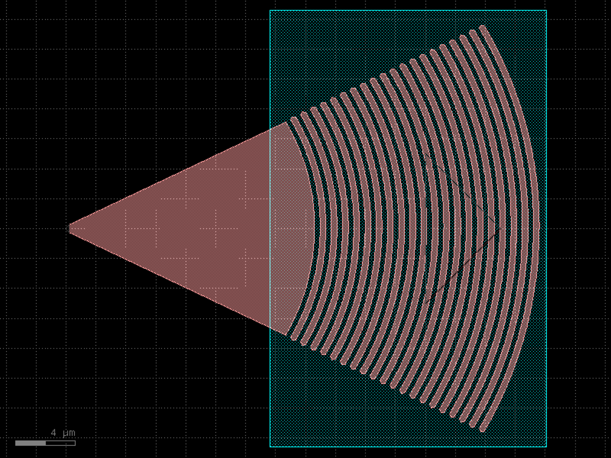
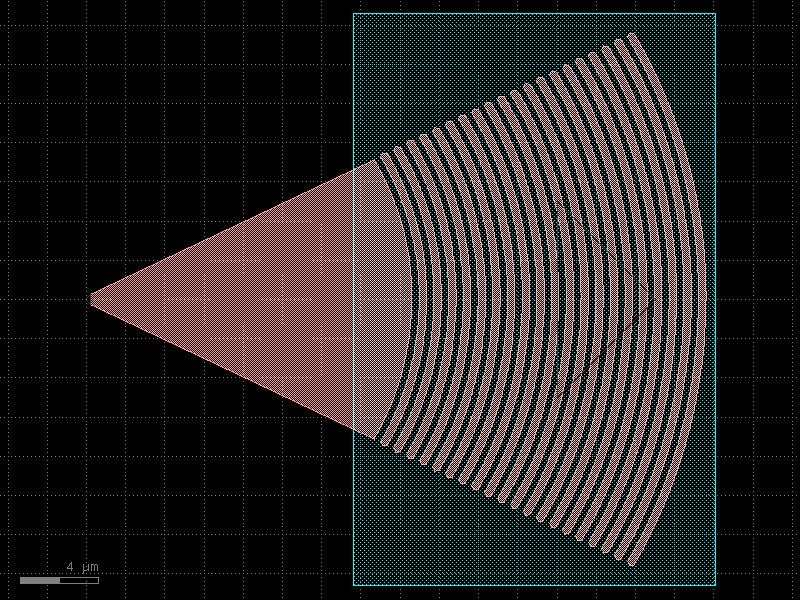
- gdsfactory.components.mzis.mzi2x2_2x2_phase_shifter(delta_length=10.0, length_y=2.0, *, length_x=200, bend='bend_euler', straight='straight', straight_y=None, straight_x_top='straight_heater_metal', straight_x_bot=None, splitter='mmi2x2', combiner='mmi2x2', with_splitter=True, port_e1_splitter='o3', port_e0_splitter='o4', port_e1_combiner='o3', port_e0_combiner='o4', port1='o1', port2='o2', nbends=2, cross_section='strip', cross_section_x_top=None, cross_section_x_bot=None, mirror_bot=False, add_optical_ports_arms=False, min_length=0.01, auto_rename_ports=True, auto_detect_port_names=False)#
Mzi.
- Parameters:
delta_length (float) – bottom arm vertical extra length.
length_y (float) – vertical length for both and top arms.
length_x (float | None) – horizontal length. None uses to the straight_x_bot/top defaults.
bend (ComponentSpec) – 90 degrees bend library.
straight (ComponentSpec) – straight function.
straight_y (ComponentSpec | None) – straight for length_y and delta_length.
straight_x_top (ComponentSpec | None) – top straight for length_x.
straight_x_bot (ComponentSpec | None) – bottom straight for length_x.
splitter (ComponentSpec) – splitter function.
combiner (ComponentSpec | None) – combiner function.
with_splitter (bool) – if False removes splitter.
port_e1_splitter (str) – east top splitter port.
port_e0_splitter (str) – east bot splitter port.
port_e1_combiner (str) – east top combiner port.
port_e0_combiner (str) – east bot combiner port.
port1 (str) – input port name.
port2 (str) – output port name.
nbends (int) – from straight top/bot to combiner (at least 2).
cross_section (CrossSectionSpec) – for routing (sxtop/sxbot to combiner).
cross_section_x_top (CrossSectionSpec | None) – optional top cross_section (defaults to cross_section).
cross_section_x_bot (CrossSectionSpec | None) – optional bottom cross_section (defaults to cross_section).
mirror_bot (bool) – if true, mirrors the bottom arm.
add_optical_ports_arms (bool) – add all other optical ports in the arms with top\_ and bot\_ prefix.
min_length (float) – minimum length for the straight.
auto_rename_ports (bool) – if True, renames ports.
auto_detect_port_names (bool) – whether to auto detect ports names. Ignores port_e* arguments if True.
- Return type:
               b2______b3
              |  sxtop  |
      straight_y        |
              |         |
              b1        b4
    splitter==|         |==combiner
              b5        b8
              |         |
      straight_y        |
              |         |
delta_length/2          |
              |         |
             b6__sxbot__b7
                  Lx
import gdsfactory as gf

gf.gpdk.PDK.activate()

c = gf.components.mzi2x2_2x2_phase_shifter(delta_length=10, length_y=2, length_x=200, bend='bend_euler', straight='straight', straight_x_top='straight_heater_metal', splitter='mmi2x2', combiner='mmi2x2', with_splitter=True, port_e1_splitter='o3', port_e0_splitter='o4', port_e1_combiner='o3', port_e0_combiner='o4', port1='o1', port2='o2', nbends=2, cross_section='strip', mirror_bot=False, add_optical_ports_arms=False, min_length=0.01, auto_rename_ports=True, auto_detect_port_names=False).copy()
c.draw_ports()
c.plot()
(Source code, png, hires.png, pdf)
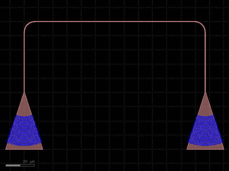
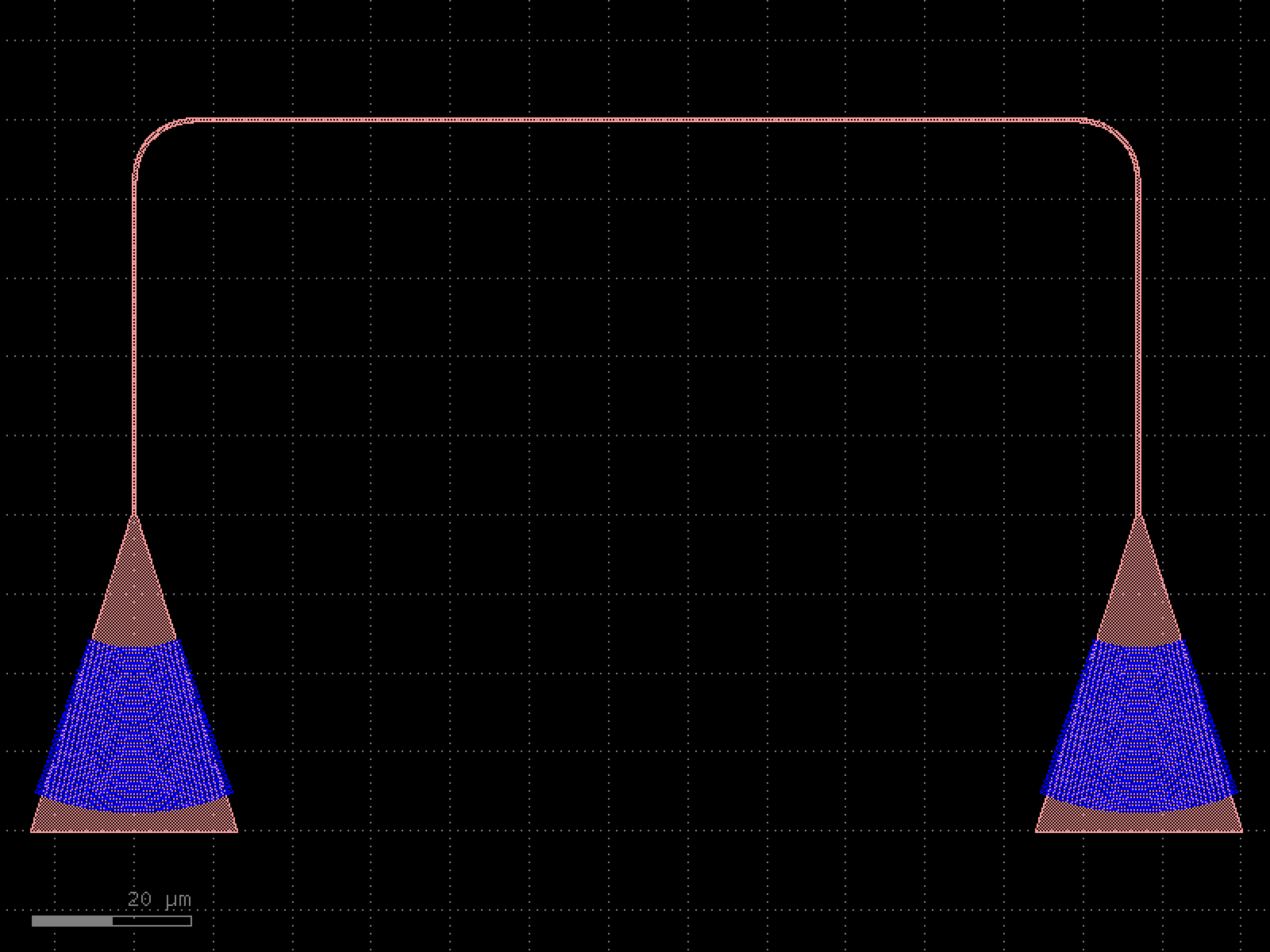

- gdsfactory.components.mzis.mzi_lattice(coupler_lengths=(10.0, 20.0), coupler_gaps=(0.2, 0.3), delta_lengths=(10.0,), mzi='mzi_coupler', splitter='coupler', **kwargs)[source]#
Mzi lattice filter.
- Parameters:
coupler_lengths (Sequence[float]) – list of length for each coupler.
coupler_gaps (Sequence[float]) – list of coupler gaps.
delta_lengths (Sequence[float]) – list of length differences.
mzi (str) – function for the mzi.
splitter (str) – splitter function.
kwargs (Any) – additional settings.
- Keyword Arguments:
length_y – vertical length for both and top arms.
length_x – horizontal length.
bend – 90 degrees bend library.
straight – straight function.
straight_y – straight for length_y and delta_length.
straight_x_top – top straight for length_x.
straight_x_bot – bottom straight for length_x.
cross_section – for routing (sxtop/sxbot to combiner).
- Return type:
      ______             ______
     |      |           |      |
     |      |           |      |
cp1==|      |===cp2=====|      |=== .... ===cp_last===
     |      |           |      |
     |      |           |      |
    DL1     |          DL2     |
     |      |           |      |
     |______|           |      |
                        |______|
import gdsfactory as gf

gf.gpdk.PDK.activate()

c = gf.components.mzi_lattice(coupler_lengths=(10, 20), coupler_gaps=(0.2, 0.3), delta_lengths=(10,), mzi='mzi_coupler', splitter='coupler').copy()
c.draw_ports()
c.plot()
(Source code, png, hires.png, pdf)
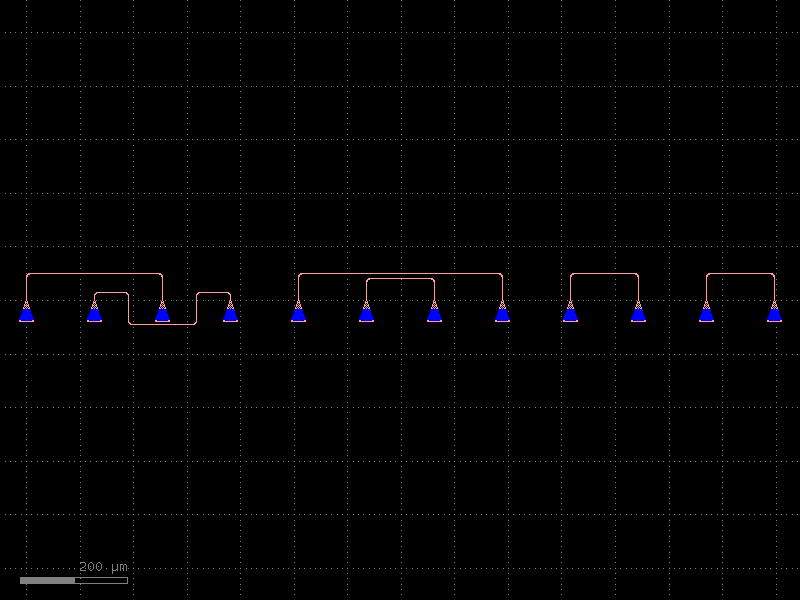
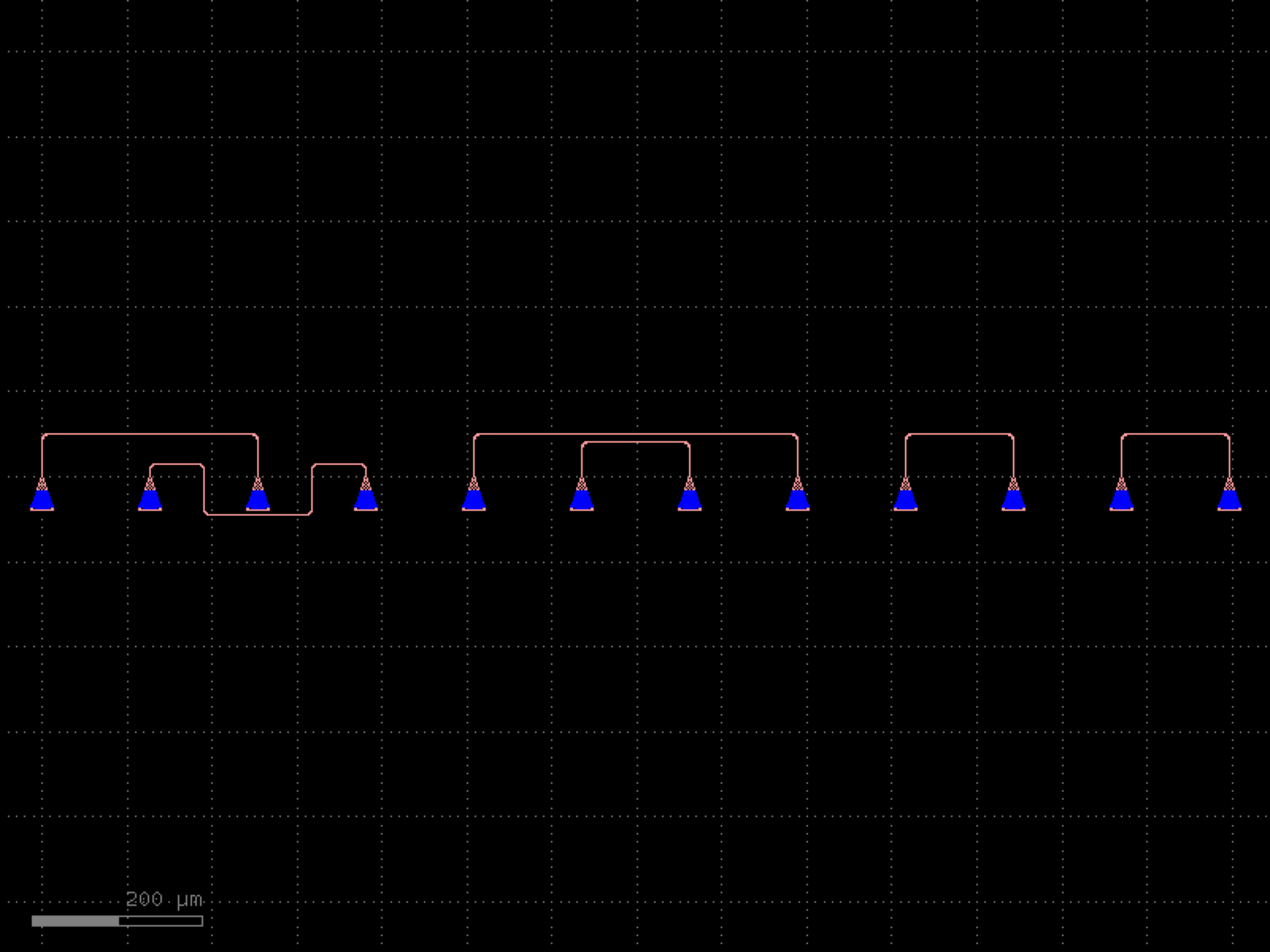

- gdsfactory.components.mzis.mzi_lattice_mmi(coupler_widths=(None, None), coupler_widths_tapers=(1.0, 1.0), coupler_lengths_tapers=(10.0, 10.0), coupler_lengths_mmis=(5.5, 5.5), coupler_widths_mmis=(2.5, 2.5), coupler_gaps_mmis=(0.25, 0.25), taper_functions_mmis=('taper', 'taper'), straight_functions_mmis=('straight', 'straight'), cross_sections_mmis=('strip', 'strip'), delta_lengths=(10.0,), mzi='mzi2x2_2x2', splitter='mmi2x2', **kwargs)[source]#
Mzi lattice filter, with MMI couplers.
- Parameters:
coupler_widths (tuple[float | None, float | None]) – (for each MMI coupler, list of) input and output straight width.
coupler_widths_tapers (tuple[float, ...]) – (for each MMI coupler, list of) interface between input straights and mmi region.
coupler_lengths_tapers (tuple[float, ...]) – (for each MMI coupler, list of) into the mmi region.
coupler_lengths_mmis (tuple[float, ...]) – (for each MMI coupler, list of) in x direction.
coupler_widths_mmis (tuple[float, ...]) – (for each MMI coupler, list of) in y direction.
coupler_gaps_mmis (tuple[float, ...]) – (for each MMI coupler, list of) (width_taper + gap between tapered wg)/2.
taper_functions_mmis (tuple[str, ...]) – (for each MMI coupler, list of) taper function.
straight_functions_mmis (tuple[str, ...]) – (for each MMI coupler, list of) straight function.
cross_sections_mmis (tuple[str, ...]) – (for each MMI coupler, list of) spec.
delta_lengths (tuple[float, ...]) – list of length differences.
mzi (str) – function for the mzi.
splitter (str) – splitter function.
kwargs (Any) – additional settings.
- Keyword Arguments:
length_y – vertical length for both and top arms.
length_x – horizontal length.
bend – 90 degrees bend library.
straight – straight function.
straight_y – straight for length_y and delta_length.
straight_x_top – top straight for length_x.
straight_x_bot – bottom straight for length_x.
cross_section – for routing (sxtop/sxbot to combiner).
- Return type:
      ______             ______
     |      |           |      |
     |      |           |      |
cp1==|      |===cp2=====|      |=== .... ===cp_last===
     |      |           |      |
     |      |           |      |
    DL1     |          DL2     |
     |      |           |      |
     |______|           |      |
                        |______|
import gdsfactory as gf

gf.gpdk.PDK.activate()

c = gf.components.mzi_lattice_mmi(coupler_widths=(None, None), coupler_widths_tapers=(1, 1), coupler_lengths_tapers=(10, 10), coupler_lengths_mmis=(5.5, 5.5), coupler_widths_mmis=(2.5, 2.5), coupler_gaps_mmis=(0.25, 0.25), taper_functions_mmis=('taper', 'taper'), straight_functions_mmis=('straight', 'straight'), cross_sections_mmis=('strip', 'strip'), delta_lengths=(10,), mzi='mzi2x2_2x2', splitter='mmi2x2').copy()
c.draw_ports()
c.plot()
(Source code, png, hires.png, pdf)
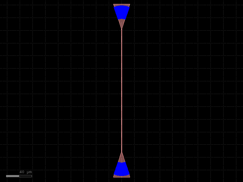
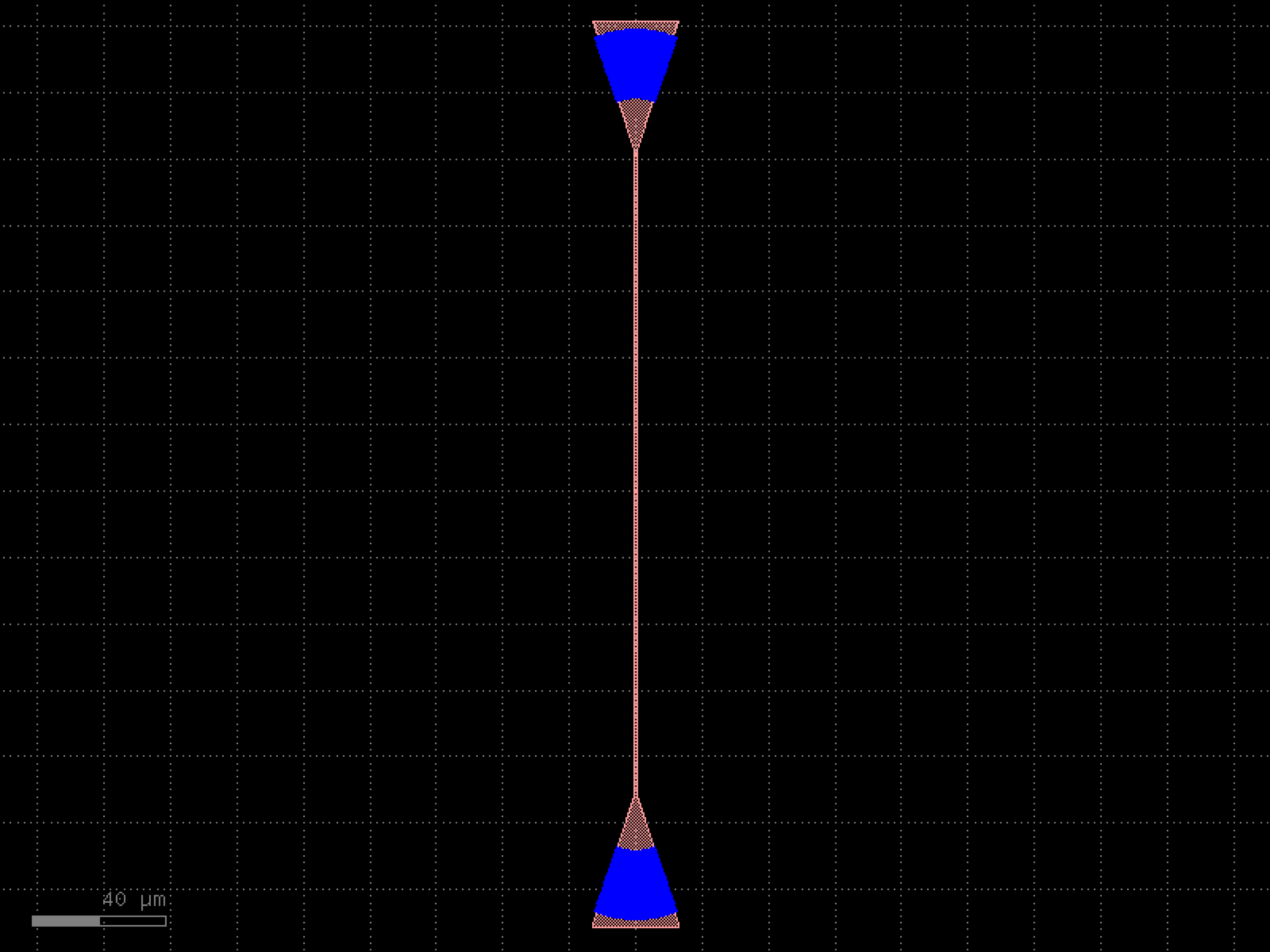

- gdsfactory.components.mzis.mzi_pads_center(ps_top='straight_heater_metal', ps_bot='straight_heater_metal', mzi='mzi', pad='pad_small', length_x=500, length_y=40, mzi_sig_top='top_r_e2', mzi_gnd_top='top_l_e2', mzi_sig_bot='bot_l_e2', mzi_gnd_bot='bot_r_e2', pad_sig_bot='e1_1_1', pad_sig_top='e3_1_3', pad_gnd_bot='e4_1_2', pad_gnd_top='e2_1_2', delta_length=40.0, cross_section='strip', cross_section_metal='metal_routing', pad_pitch='pad_pitch', auto_taper=False, **kwargs)[source]#
Return Mzi phase shifter with pads in the middle.
GND is the middle pad and is shared between top and bottom phase shifters.
- Parameters:
ps_top (ComponentSpec) – phase shifter top.
ps_bot (ComponentSpec) – phase shifter bottom.
mzi (ComponentSpec) – interferometer.
pad (ComponentSpec) – pad function.
length_x (float) – horizontal length.
length_y (float) – vertical length.
mzi_sig_top (str | None) – port name for top phase shifter signal. None if no connection.
mzi_gnd_top (str | None) – port name for top phase shifter GND. None if no connection.
mzi_sig_bot (str | None) – port name for top phase shifter signal. None if no connection.
mzi_gnd_bot (str | None) – port name for top phase shifter GND. None if no connection.
pad_sig_bot (str) – port name for top pad.
pad_sig_top (str) – port name for top pad.
pad_gnd_bot (str) – port name for top pad.
pad_gnd_top (str) – port name for top pad.
delta_length (float) – mzi length imbalance.
cross_section (CrossSectionSpec) – for the mzi.
cross_section_metal (CrossSectionSpec) – for routing metal.
pad_pitch (float | str) – pad pitch in um.
auto_taper (bool) – add taper if cross_section width is different between mzi and pad.
kwargs (Any) – routing settings.
- Return type:
import gdsfactory as gf

gf.gpdk.PDK.activate()

c = gf.components.mzi_pads_center(ps_top='straight_heater_metal', ps_bot='straight_heater_metal', mzi='mzi', pad='pad_small', length_x=500, length_y=40, mzi_sig_top='top_r_e2', mzi_gnd_top='top_l_e2', mzi_sig_bot='bot_l_e2', mzi_gnd_bot='bot_r_e2', pad_sig_bot='e1_1_1', pad_sig_top='e3_1_3', pad_gnd_bot='e4_1_2', pad_gnd_top='e2_1_2', delta_length=40, cross_section='strip', cross_section_metal='metal_routing', pad_pitch='pad_pitch', auto_taper=False).copy()
c.draw_ports()
c.plot()
(Source code, png, hires.png, pdf)
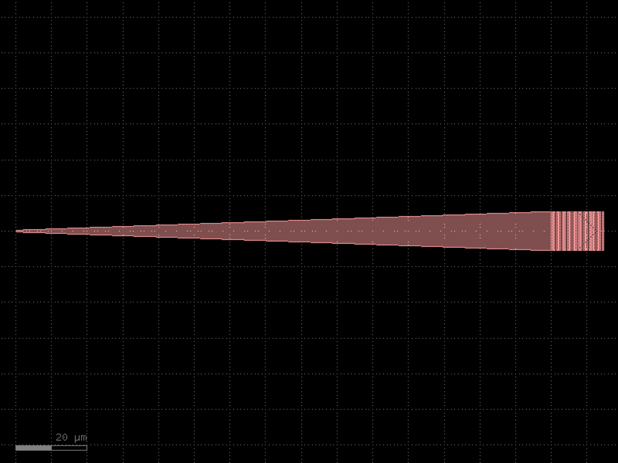
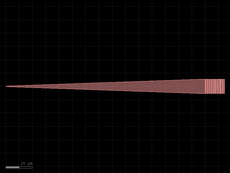
- gdsfactory.components.mzis.mzi_phase_shifter(delta_length=10.0, length_y=2.0, *, length_x=200, bend='bend_euler', straight='straight', straight_y=None, straight_x_top='straight_heater_metal', straight_x_bot=None, splitter='mmi1x2', combiner=None, with_splitter=True, port_e1_splitter='o2', port_e0_splitter='o3', port_e1_combiner='o2', port_e0_combiner='o3', port1='o1', port2='o2', nbends=2, cross_section='strip', cross_section_x_top=None, cross_section_x_bot=None, mirror_bot=False, add_optical_ports_arms=False, min_length=0.01, auto_rename_ports=True, auto_detect_port_names=False)#
Mzi.
- Parameters:
delta_length (float) – bottom arm vertical extra length.
length_y (float) – vertical length for both and top arms.
length_x (float | None) – horizontal length. None uses to the straight_x_bot/top defaults.
bend (ComponentSpec) – 90 degrees bend library.
straight (ComponentSpec) – straight function.
straight_y (ComponentSpec | None) – straight for length_y and delta_length.
straight_x_top (ComponentSpec | None) – top straight for length_x.
straight_x_bot (ComponentSpec | None) – bottom straight for length_x.
splitter (ComponentSpec) – splitter function.
combiner (ComponentSpec | None) – combiner function.
with_splitter (bool) – if False removes splitter.
port_e1_splitter (str) – east top splitter port.
port_e0_splitter (str) – east bot splitter port.
port_e1_combiner (str) – east top combiner port.
port_e0_combiner (str) – east bot combiner port.
port1 (str) – input port name.
port2 (str) – output port name.
nbends (int) – from straight top/bot to combiner (at least 2).
cross_section (CrossSectionSpec) – for routing (sxtop/sxbot to combiner).
cross_section_x_top (CrossSectionSpec | None) – optional top cross_section (defaults to cross_section).
cross_section_x_bot (CrossSectionSpec | None) – optional bottom cross_section (defaults to cross_section).
mirror_bot (bool) – if true, mirrors the bottom arm.
add_optical_ports_arms (bool) – add all other optical ports in the arms with top\_ and bot\_ prefix.
min_length (float) – minimum length for the straight.
auto_rename_ports (bool) – if True, renames ports.
auto_detect_port_names (bool) – whether to auto detect ports names. Ignores port_e* arguments if True.
- Return type:
               b2______b3
              |  sxtop  |
      straight_y        |
              |         |
              b1        b4
    splitter==|         |==combiner
              b5        b8
              |         |
      straight_y        |
              |         |
delta_length/2          |
              |         |
             b6__sxbot__b7
                  Lx
import gdsfactory as gf

gf.gpdk.PDK.activate()

c = gf.components.mzi_phase_shifter(delta_length=10, length_y=2, length_x=200, bend='bend_euler', straight='straight', straight_x_top='straight_heater_metal', splitter='mmi1x2', with_splitter=True, port_e1_splitter='o2', port_e0_splitter='o3', port_e1_combiner='o2', port_e0_combiner='o3', port1='o1', port2='o2', nbends=2, cross_section='strip', mirror_bot=False, add_optical_ports_arms=False, min_length=0.01, auto_rename_ports=True, auto_detect_port_names=False).copy()
c.draw_ports()
c.plot()
(Source code, png, hires.png, pdf)
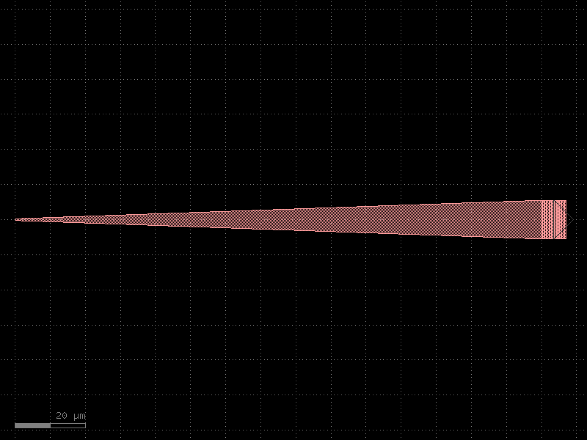
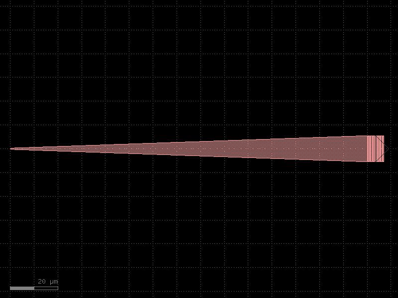
- gdsfactory.components.mzis.mzi_phase_shifter_top_heater_metal(delta_length=10.0, length_y=2.0, *, length_x=200, bend='bend_euler', straight='straight', straight_y=None, straight_x_top='straight_heater_metal', straight_x_bot=None, splitter='mmi1x2', combiner=None, with_splitter=True, port_e1_splitter='o2', port_e0_splitter='o3', port_e1_combiner='o2', port_e0_combiner='o3', port1='o1', port2='o2', nbends=2, cross_section='strip', cross_section_x_top=None, cross_section_x_bot=None, mirror_bot=False, add_optical_ports_arms=False, min_length=0.01, auto_rename_ports=True, auto_detect_port_names=False)#
Mzi.
- Parameters:
delta_length (float) – bottom arm vertical extra length.
length_y (float) – vertical length for both and top arms.
length_x (float | None) – horizontal length. None uses to the straight_x_bot/top defaults.
bend (ComponentSpec) – 90 degrees bend library.
straight (ComponentSpec) – straight function.
straight_y (ComponentSpec | None) – straight for length_y and delta_length.
straight_x_top (ComponentSpec | None) – top straight for length_x.
straight_x_bot (ComponentSpec | None) – bottom straight for length_x.
splitter (ComponentSpec) – splitter function.
combiner (ComponentSpec | None) – combiner function.
with_splitter (bool) – if False removes splitter.
port_e1_splitter (str) – east top splitter port.
port_e0_splitter (str) – east bot splitter port.
port_e1_combiner (str) – east top combiner port.
port_e0_combiner (str) – east bot combiner port.
port1 (str) – input port name.
port2 (str) – output port name.
nbends (int) – from straight top/bot to combiner (at least 2).
cross_section (CrossSectionSpec) – for routing (sxtop/sxbot to combiner).
cross_section_x_top (CrossSectionSpec | None) – optional top cross_section (defaults to cross_section).
cross_section_x_bot (CrossSectionSpec | None) – optional bottom cross_section (defaults to cross_section).
mirror_bot (bool) – if true, mirrors the bottom arm.
add_optical_ports_arms (bool) – add all other optical ports in the arms with top\_ and bot\_ prefix.
min_length (float) – minimum length for the straight.
auto_rename_ports (bool) – if True, renames ports.
auto_detect_port_names (bool) – whether to auto detect ports names. Ignores port_e* arguments if True.
- Return type:
               b2______b3
              |  sxtop  |
      straight_y        |
              |         |
              b1        b4
    splitter==|         |==combiner
              b5        b8
              |         |
      straight_y        |
              |         |
delta_length/2          |
              |         |
             b6__sxbot__b7
                  Lx
import gdsfactory as gf

gf.gpdk.PDK.activate()

c = gf.components.mzi_phase_shifter_top_heater_metal(delta_length=10, length_y=2, length_x=200, bend='bend_euler', straight='straight', straight_x_top='straight_heater_metal', splitter='mmi1x2', with_splitter=True, port_e1_splitter='o2', port_e0_splitter='o3', port_e1_combiner='o2', port_e0_combiner='o3', port1='o1', port2='o2', nbends=2, cross_section='strip', mirror_bot=False, add_optical_ports_arms=False, min_length=0.01, auto_rename_ports=True, auto_detect_port_names=False).copy()
c.draw_ports()
c.plot()
(Source code, png, hires.png, pdf)
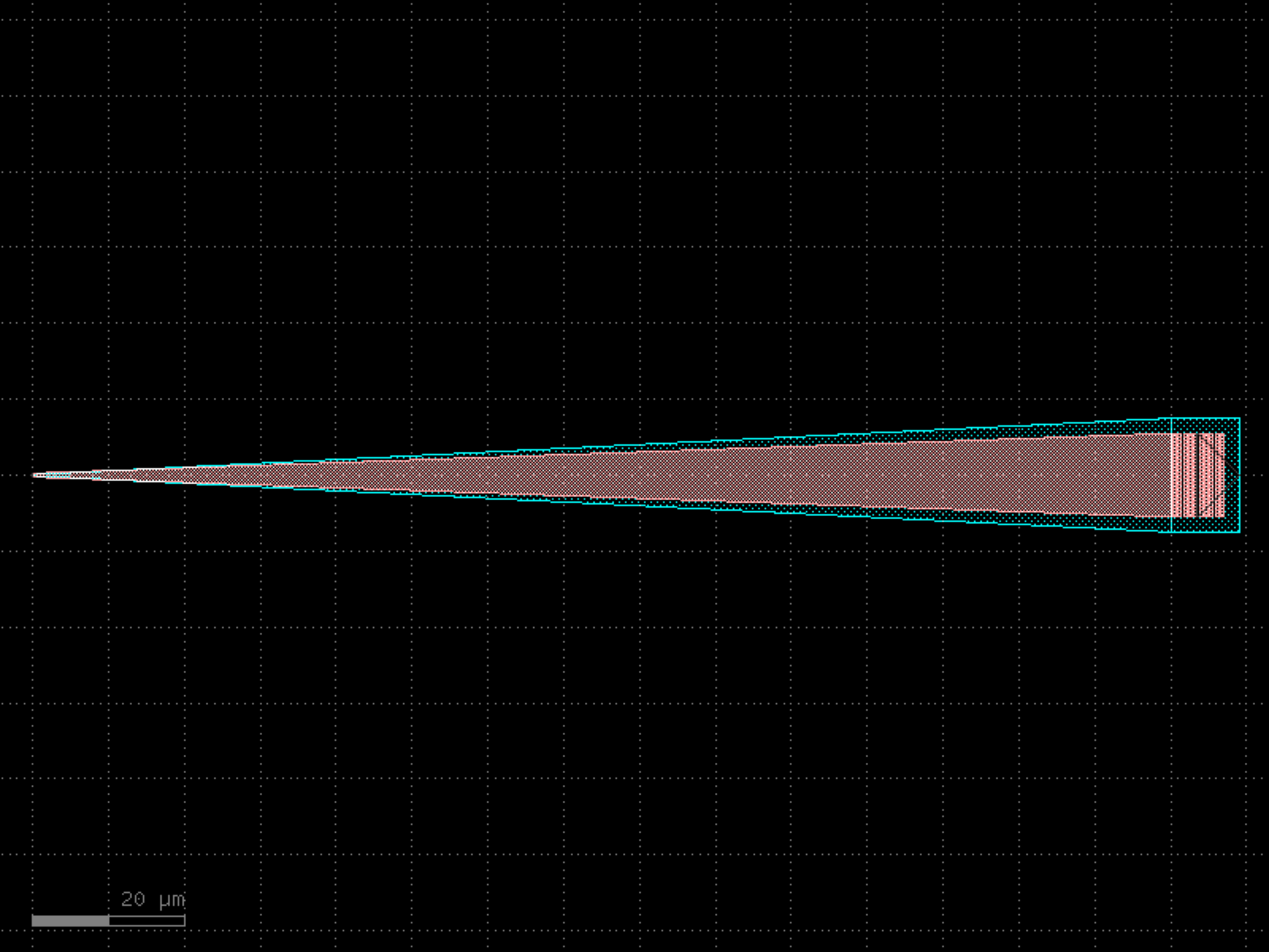

- gdsfactory.components.mzis.mzi_pin(*, delta_length=0.0, length_y=2.0, length_x=100, bend='bend_euler', straight='straight', straight_y=None, straight_x_top='straight_pin', straight_x_bot=None, splitter='mmi1x2', combiner=None, with_splitter=True, port_e1_splitter='o2', port_e0_splitter='o3', port_e1_combiner='o2', port_e0_combiner='o3', port1='o1', port2='o2', nbends=2, cross_section='strip', cross_section_x_top='pin', cross_section_x_bot=None, mirror_bot=False, add_optical_ports_arms=False, min_length=0.01, auto_rename_ports=True, auto_detect_port_names=False)#
Mzi.
- Parameters:
delta_length (float) – bottom arm vertical extra length.
length_y (float) – vertical length for both and top arms.
length_x (float | None) – horizontal length. None uses to the straight_x_bot/top defaults.
bend (ComponentSpec) – 90 degrees bend library.
straight (ComponentSpec) – straight function.
straight_y (ComponentSpec | None) – straight for length_y and delta_length.
straight_x_top (ComponentSpec | None) – top straight for length_x.
straight_x_bot (ComponentSpec | None) – bottom straight for length_x.
splitter (ComponentSpec) – splitter function.
combiner (ComponentSpec | None) – combiner function.
with_splitter (bool) – if False removes splitter.
port_e1_splitter (str) – east top splitter port.
port_e0_splitter (str) – east bot splitter port.
port_e1_combiner (str) – east top combiner port.
port_e0_combiner (str) – east bot combiner port.
port1 (str) – input port name.
port2 (str) – output port name.
nbends (int) – from straight top/bot to combiner (at least 2).
cross_section (CrossSectionSpec) – for routing (sxtop/sxbot to combiner).
cross_section_x_top (CrossSectionSpec | None) – optional top cross_section (defaults to cross_section).
cross_section_x_bot (CrossSectionSpec | None) – optional bottom cross_section (defaults to cross_section).
mirror_bot (bool) – if true, mirrors the bottom arm.
add_optical_ports_arms (bool) – add all other optical ports in the arms with top\_ and bot\_ prefix.
min_length (float) – minimum length for the straight.
auto_rename_ports (bool) – if True, renames ports.
auto_detect_port_names (bool) – whether to auto detect ports names. Ignores port_e* arguments if True.
- Return type:
               b2______b3
              |  sxtop  |
      straight_y        |
              |         |
              b1        b4
    splitter==|         |==combiner
              b5        b8
              |         |
      straight_y        |
              |         |
delta_length/2          |
              |         |
             b6__sxbot__b7
                  Lx
import gdsfactory as gf

gf.gpdk.PDK.activate()

c = gf.components.mzi_pin(delta_length=0, length_y=2, length_x=100, bend='bend_euler', straight='straight', straight_x_top='straight_pin', splitter='mmi1x2', with_splitter=True, port_e1_splitter='o2', port_e0_splitter='o3', port_e1_combiner='o2', port_e0_combiner='o3', port1='o1', port2='o2', nbends=2, cross_section='strip', cross_section_x_top='pin', mirror_bot=False, add_optical_ports_arms=False, min_length=0.01, auto_rename_ports=True, auto_detect_port_names=False).copy()
c.draw_ports()
c.plot()
(Source code, png, hires.png, pdf)
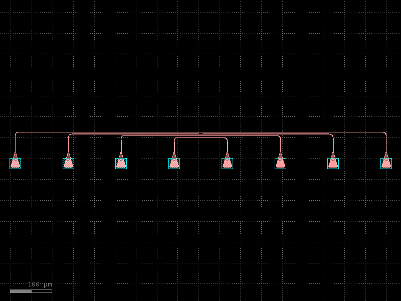
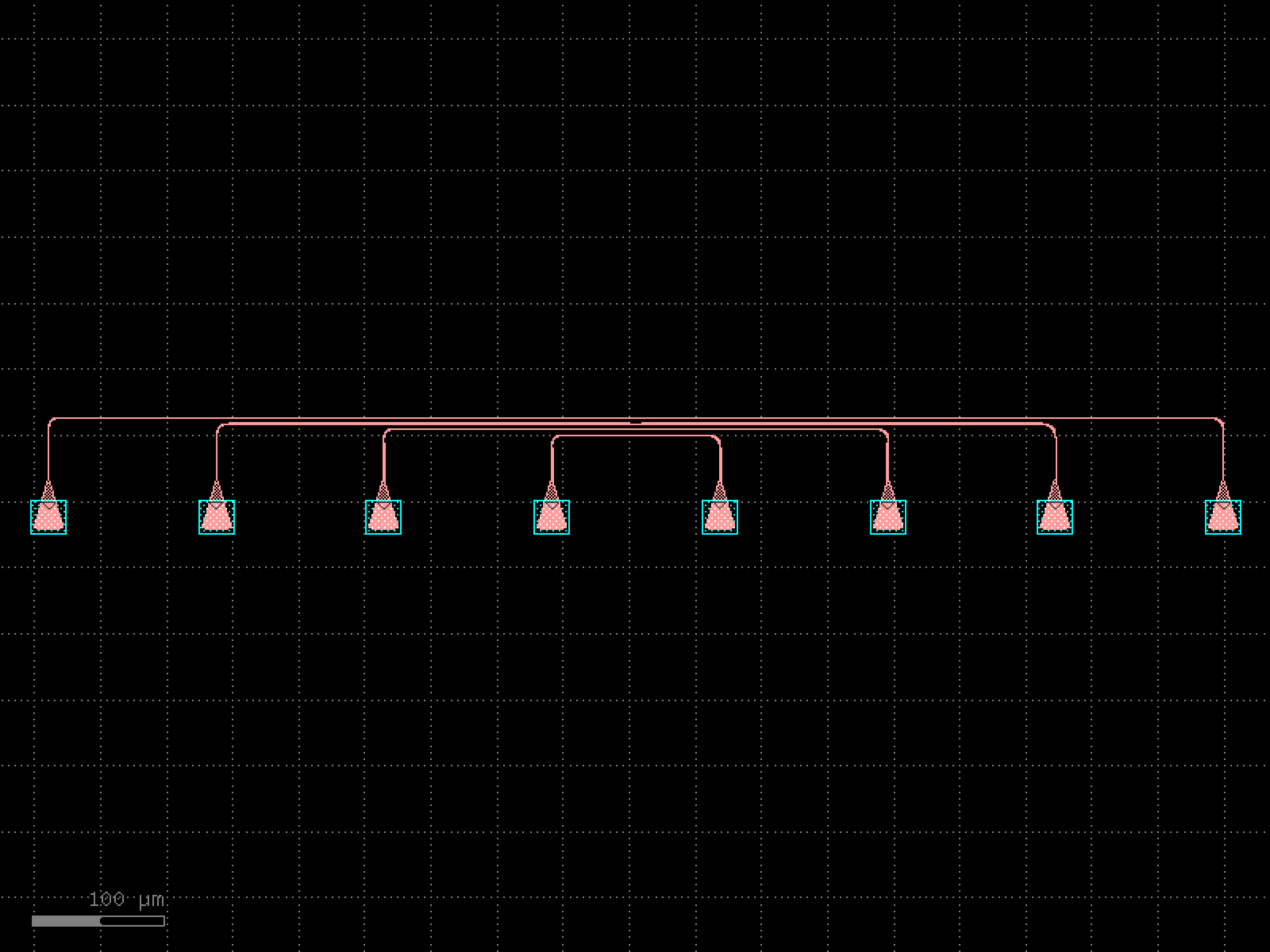

- gdsfactory.components.mzis.mzit(w0=0.5, w1=0.45, w2=0.55, dy=2.0, delta_length=10.0, length=1.0, coupler_length1=5.0, coupler_length2=10.0, coupler_gap1=0.2, coupler_gap2=0.3, taper='taper', taper_length=5.0, bend90='bend_euler', straight='straight', coupler1='coupler', coupler2='coupler', cross_section='strip')[source]#
Mzi tolerant to fabrication variations.
based on Yufei Xing thesis http://photonics.intec.ugent.be/publications/PhD.asp?ID=250
- Parameters:
w0 (float) – input waveguide width (um).
w1 (float) – narrow waveguide width (um).
w2 (float) – wide waveguide width (um).
dy (Delta) – port to port vertical spacing.
delta_length (float) – length difference between arms (um).
length (float) – shared length for w1 and w2.
coupler_length1 (float) – length of coupler1.
coupler_length2 (float) – length of coupler2.
coupler_gap1 (float) – coupler1.
coupler_gap2 (float) – coupler2.
taper (ComponentSpec) – taper spec.
taper_length (float) – from w0 to w1.
bend90 (ComponentSpec) – bend spec.
straight (ComponentSpec) – spec.
coupler1 (ComponentSpec | None) – coupler1 spec (optional).
coupler2 (ComponentSpec) – coupler2 spec.
cross_section (str) – cross_section spec.
- Return type:
               cp1
4   2 __                  __  3___w0_t2   _w2___
        \                /                      \
         \    length1   /                        |
          ============== gap1                    |
         /              \                        |
      __/                \_____w0___t1   _w1     |
3   1                        4               \   |
                                             |   |
2   2                                        |   |
      __                  __w0____t1____w1___/   |
        \                /                       |
         \    length2   /                        |
          ============== gap2                    |
         /               \                       |                       |
      __/                 \ E0_w0__t2 __w1______/
1   1
               cp2
import gdsfactory as gf

gf.gpdk.PDK.activate()

c = gf.components.mzit(w0=0.5, w1=0.45, w2=0.55, dy=2, delta_length=10, length=1, coupler_length1=5, coupler_length2=10, coupler_gap1=0.2, coupler_gap2=0.3, taper='taper', taper_length=5, bend90='bend_euler', straight='straight', coupler1='coupler', coupler2='coupler', cross_section='strip').copy()
c.draw_ports()
c.plot()
(Source code, png, hires.png, pdf)
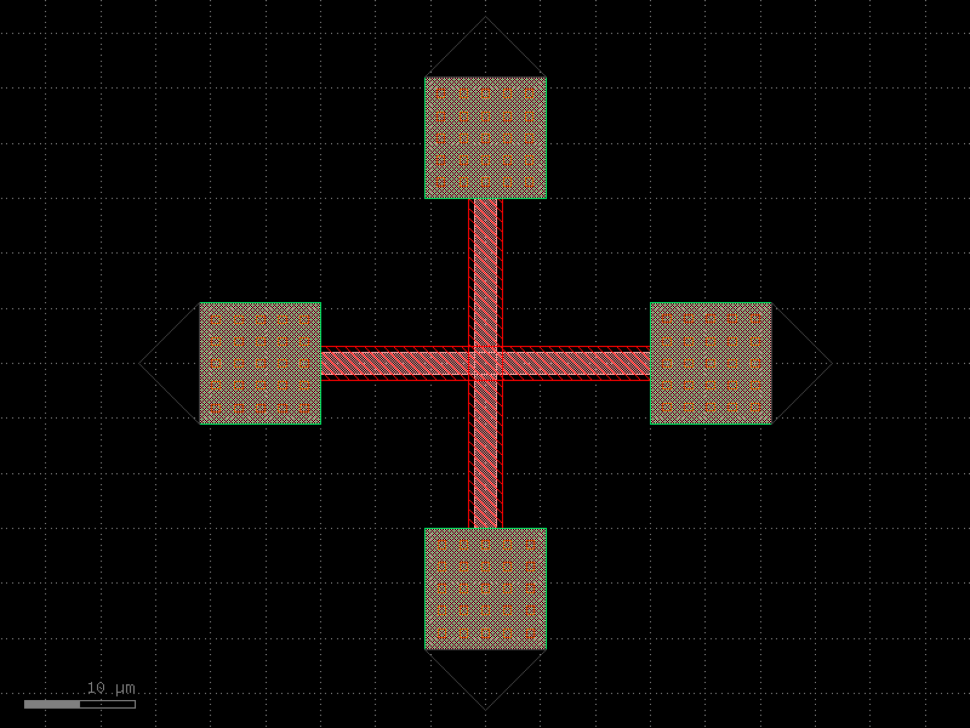
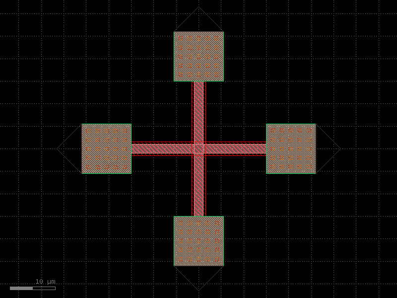
- gdsfactory.components.mzis.mzit_lattice(coupler_lengths=(10.0, 20.0), coupler_gaps=(0.2, 0.3), delta_lengths=(10.0, ), mzi=<function mzit>)[source]#
Mzi fab tolerant lattice filter.
                cp1
o4  o2 __                  __ o3___w0_t2   _w2___
         \                /                      \
          \    length1   /                        |
           ============== gap1                    |
          /              \                        |
       __/                \_____w0___t1   _w1     |
o3  o1                       o4               \   | .
                 ...                          |   | .
o2  o2                    o3                  |   | .
       __                  _____w0___t1___w1__/   |
         \                /                       |
          \    lengthN   /                        |
           ============== gapN                    |
          /               \                       |
       __/                 \_                     |
o1  o1                      \___w0___t2___w1_____/
                cpN       o4
- Parameters:
coupler_lengths (Sequence[float])
coupler_gaps (Sequence[float])
delta_lengths (Sequence[float])
mzi (ComponentSpec)
- Return type:
import gdsfactory as gf

gf.gpdk.PDK.activate()

c = gf.components.mzit_lattice(coupler_lengths=(10, 20), coupler_gaps=(0.2, 0.3), delta_lengths=(10,)).copy()
c.draw_ports()
c.plot()
(Source code, png, hires.png, pdf)
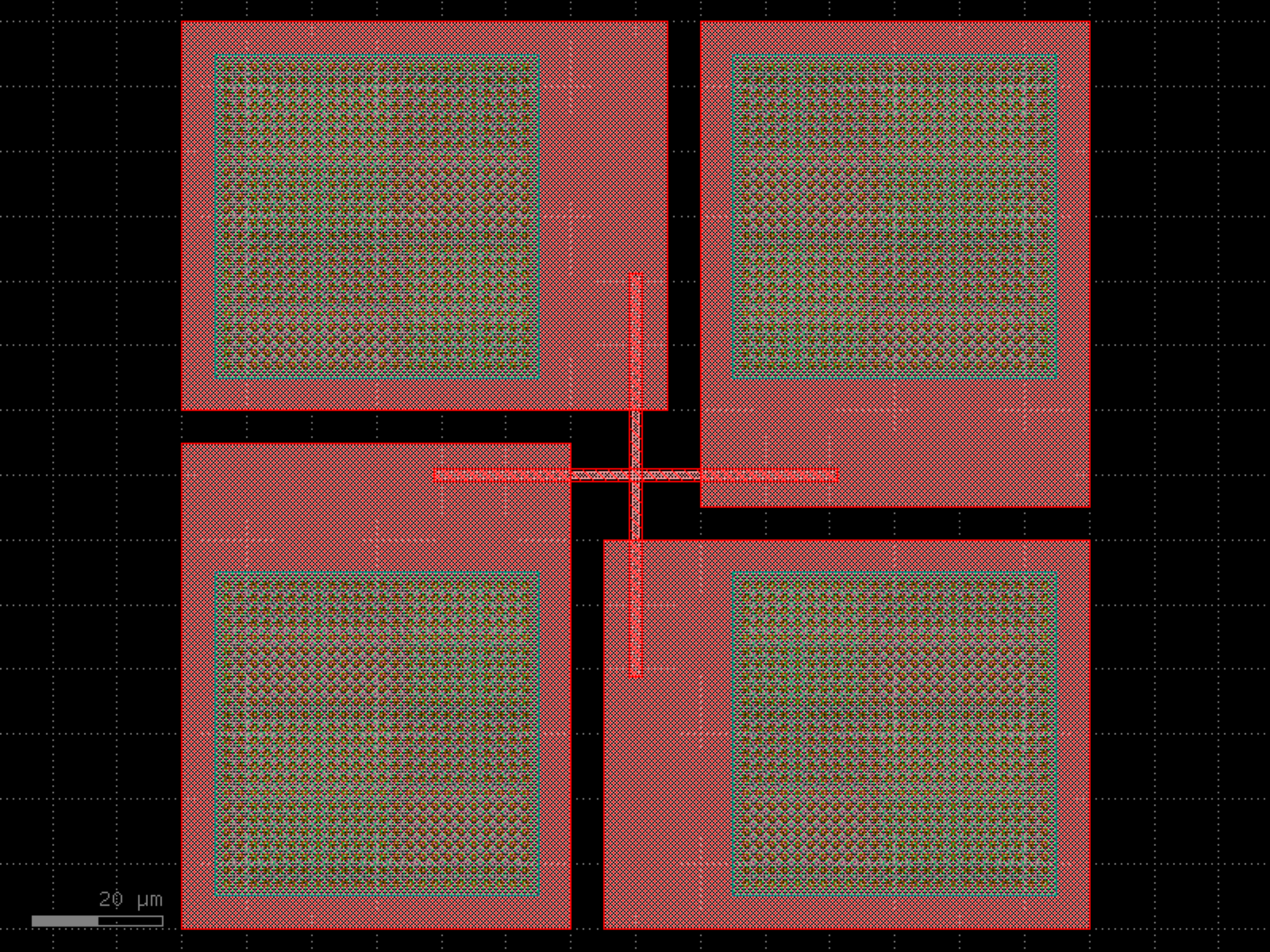
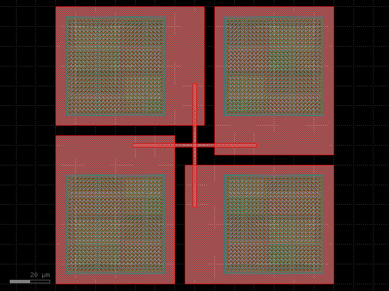
- gdsfactory.components.mzis.mzm(delta_length=10.0, length_y=2.0, *, length_x=200, bend='bend_euler', straight='straight', straight_y=None, straight_x_top='straight_pin', straight_x_bot='straight_pin', splitter='mmi1x2', combiner=None, with_splitter=True, port_e1_splitter='o2', port_e0_splitter='o3', port_e1_combiner='o2', port_e0_combiner='o3', port1='o1', port2='o2', nbends=2, cross_section='strip', cross_section_x_top=None, cross_section_x_bot=None, mirror_bot=False, add_optical_ports_arms=False, min_length=0.01, auto_rename_ports=True, auto_detect_port_names=False)#
Mzi.
- Parameters:
delta_length (float) – bottom arm vertical extra length.
length_y (float) – vertical length for both and top arms.
length_x (float | None) – horizontal length. None uses to the straight_x_bot/top defaults.
bend (ComponentSpec) – 90 degrees bend library.
straight (ComponentSpec) – straight function.
straight_y (ComponentSpec | None) – straight for length_y and delta_length.
straight_x_top (ComponentSpec | None) – top straight for length_x.
straight_x_bot (ComponentSpec | None) – bottom straight for length_x.
splitter (ComponentSpec) – splitter function.
combiner (ComponentSpec | None) – combiner function.
with_splitter (bool) – if False removes splitter.
port_e1_splitter (str) – east top splitter port.
port_e0_splitter (str) – east bot splitter port.
port_e1_combiner (str) – east top combiner port.
port_e0_combiner (str) – east bot combiner port.
port1 (str) – input port name.
port2 (str) – output port name.
nbends (int) – from straight top/bot to combiner (at least 2).
cross_section (CrossSectionSpec) – for routing (sxtop/sxbot to combiner).
cross_section_x_top (CrossSectionSpec | None) – optional top cross_section (defaults to cross_section).
cross_section_x_bot (CrossSectionSpec | None) – optional bottom cross_section (defaults to cross_section).
mirror_bot (bool) – if true, mirrors the bottom arm.
add_optical_ports_arms (bool) – add all other optical ports in the arms with top\_ and bot\_ prefix.
min_length (float) – minimum length for the straight.
auto_rename_ports (bool) – if True, renames ports.
auto_detect_port_names (bool) – whether to auto detect ports names. Ignores port_e* arguments if True.
- Return type:
               b2______b3
              |  sxtop  |
      straight_y        |
              |         |
              b1        b4
    splitter==|         |==combiner
              b5        b8
              |         |
      straight_y        |
              |         |
delta_length/2          |
              |         |
             b6__sxbot__b7
                  Lx
import gdsfactory as gf

gf.gpdk.PDK.activate()

c = gf.components.mzm(delta_length=10, length_y=2, length_x=200, bend='bend_euler', straight='straight', straight_x_top='straight_pin', straight_x_bot='straight_pin', splitter='mmi1x2', with_splitter=True, port_e1_splitter='o2', port_e0_splitter='o3', port_e1_combiner='o2', port_e0_combiner='o3', port1='o1', port2='o2', nbends=2, cross_section='strip', mirror_bot=False, add_optical_ports_arms=False, min_length=0.01, auto_rename_ports=True, auto_detect_port_names=False).copy()
c.draw_ports()
c.plot()
(Source code, png, hires.png, pdf)
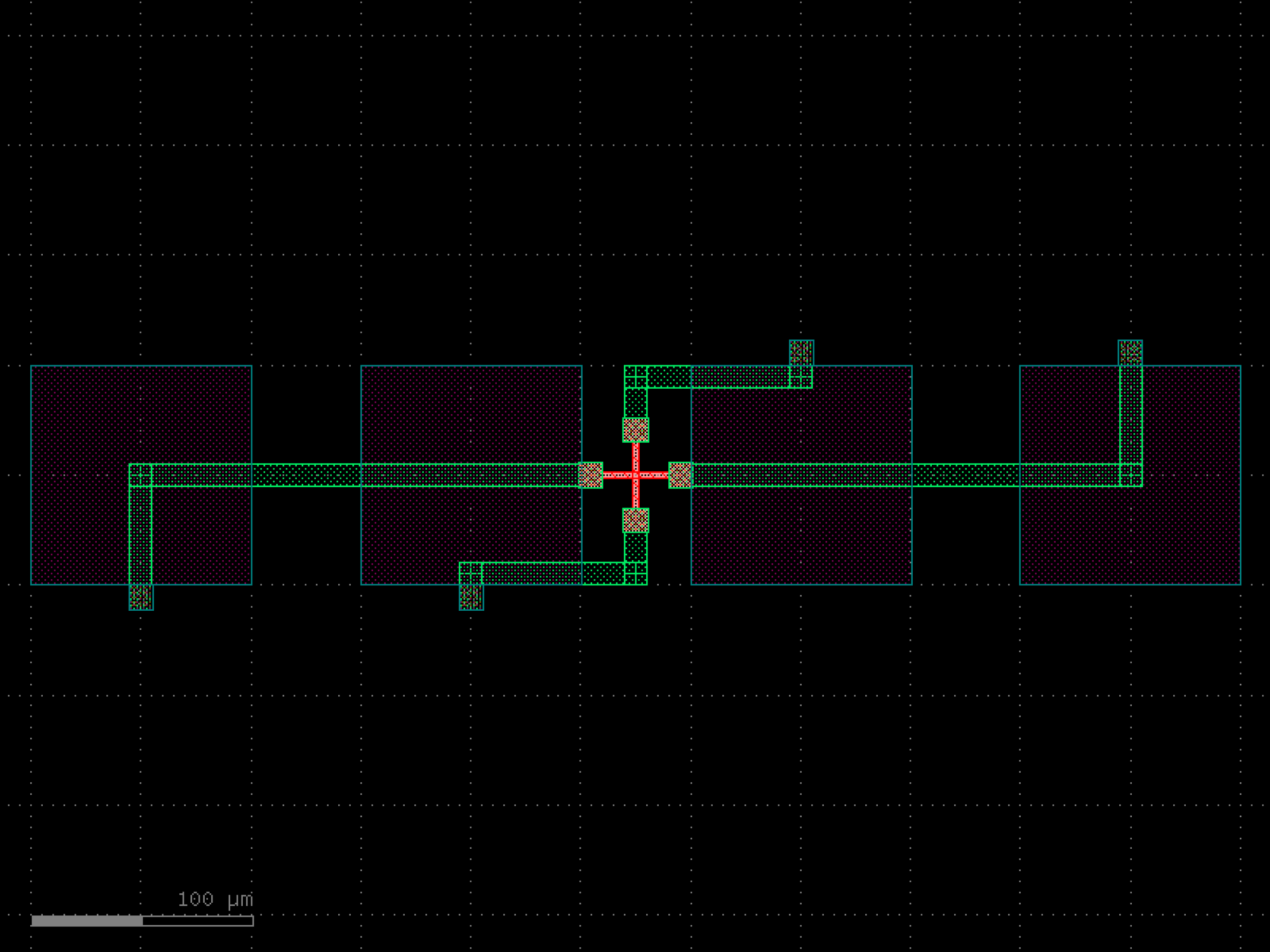
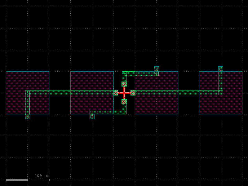
pads#
- gdsfactory.components.pads.bump_pad(size=36.244, layer='MTOP', port_width=10.0, port_layer='M2', port_type='pad', add_via=True)[source]#
Returns rectangular pad with ports.
- Parameters:
size (float) – octagon edge of octagon.
layer (LayerSpec) – bump pad layer.
port_width (float) – width of the port for electrical routing.
port_layer (LayerSpec) – layer of the port for electrical routing.
port_type (str) – port type for pad port.
add_via (bool) – whether to add a via stack.
- Return type:
import gdsfactory as gf

gf.gpdk.PDK.activate()

c = gf.components.bump_pad(size=36.244, layer='MTOP', port_width=10, port_layer='M2', port_type='pad', add_via=True).copy()
c.draw_ports()
c.plot()
(Source code, png, hires.png, pdf)
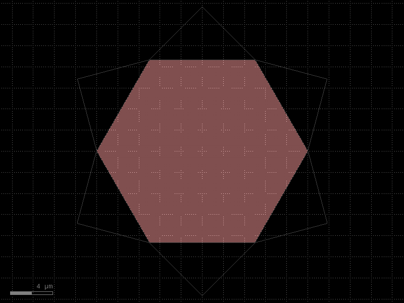

- gdsfactory.components.pads.bump_pad_grid(columns=6, rows=6, column_pitch=121.89, row_pitch=132.66, offset=66.33, port_width=10, port_layer='M2', size=36.244, layer='MTOP', auto_rename_ports=False, skip_pads=None, add_via=True)[source]#
Returns 2D array of bump pads.
- Parameters:
columns (int) – number of columns.
rows (int) – number of rows.
column_pitch (float) – x pitch.
row_pitch (float) – y pitch.
offset (float) – offset for alternating columns.
port_width (float) – width of the port for electrical routing.
port_layer (LayerSpec) – layer of the port for electrical routing.
size (float) – pad size.
layer (LayerSpec) – bump pad layer.
auto_rename_ports (bool) – True to auto rename ports.
skip_pads (list[tuple[int, int]] | None) – list of (col, row) tuples to skip.
add_via (bool) – whether to add a via stack.
- Return type:
import gdsfactory as gf

gf.gpdk.PDK.activate()

c = gf.components.bump_pad_grid(columns=6, rows=6, column_pitch=121.89, row_pitch=132.66, offset=66.33, port_width=10, port_layer='M2', size=36.244, layer='MTOP', auto_rename_ports=False, add_via=True).copy()
c.draw_ports()
c.plot()
(Source code, png, hires.png, pdf)
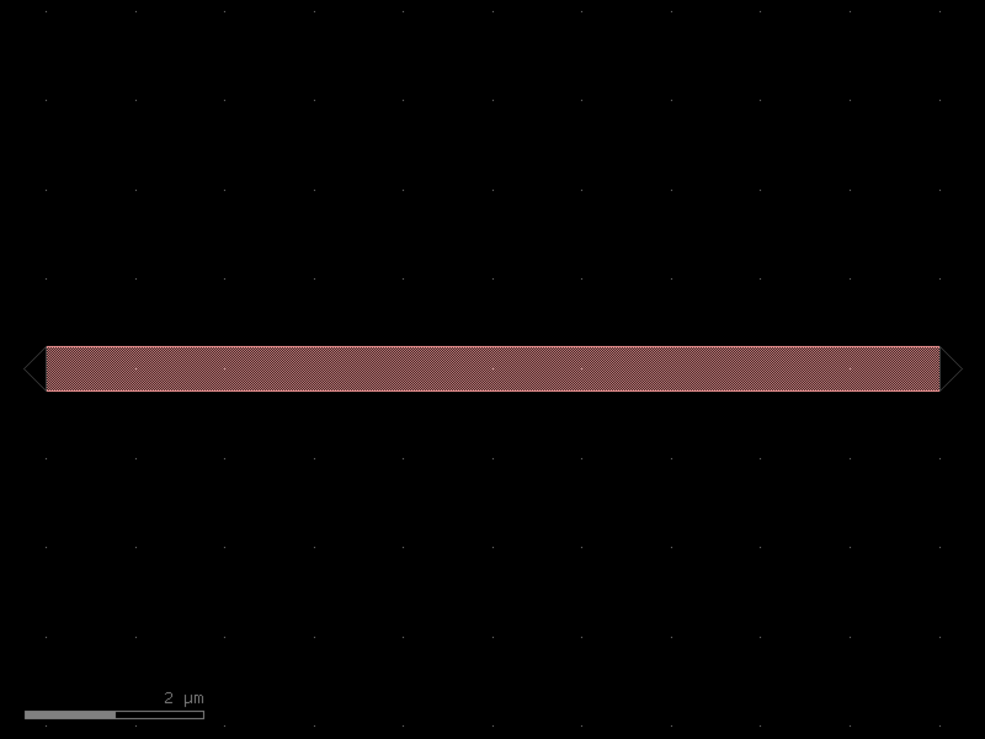

- gdsfactory.components.pads.pad(size=(100.0, 100.0), layer='MTOP', bbox_layers=None, bbox_offsets=None, port_inclusion=0, port_orientation=0, port_orientations=(180, 90, 0, -90), port_type='pad')[source]#
Returns rectangular pad with ports.
- Parameters:
size (tuple[float, float] | str) – x, y size.
layer (LayerSpec) – pad layer.
bbox_layers (tuple[LayerSpec, ...] | None) – list of layers.
bbox_offsets (tuple[float, ...] | None) – Optional offsets for each layer with respect to size. positive grows, negative shrinks the size.
port_inclusion (float) – from edge.
port_orientation (float | None) – in degrees for the center port.
port_orientations (tuple[int, ...] | list[int] | None) – list of port_orientations to add. None does not add ports.
port_type (str) – port type for pad port.
- Return type:
import gdsfactory as gf

gf.gpdk.PDK.activate()

c = gf.components.pad(size=(100, 100), layer='MTOP', port_inclusion=0, port_orientation=0, port_orientations=(180, 90, 0, -90), port_type='pad').copy()
c.draw_ports()
c.plot()
(Source code, png, hires.png, pdf)
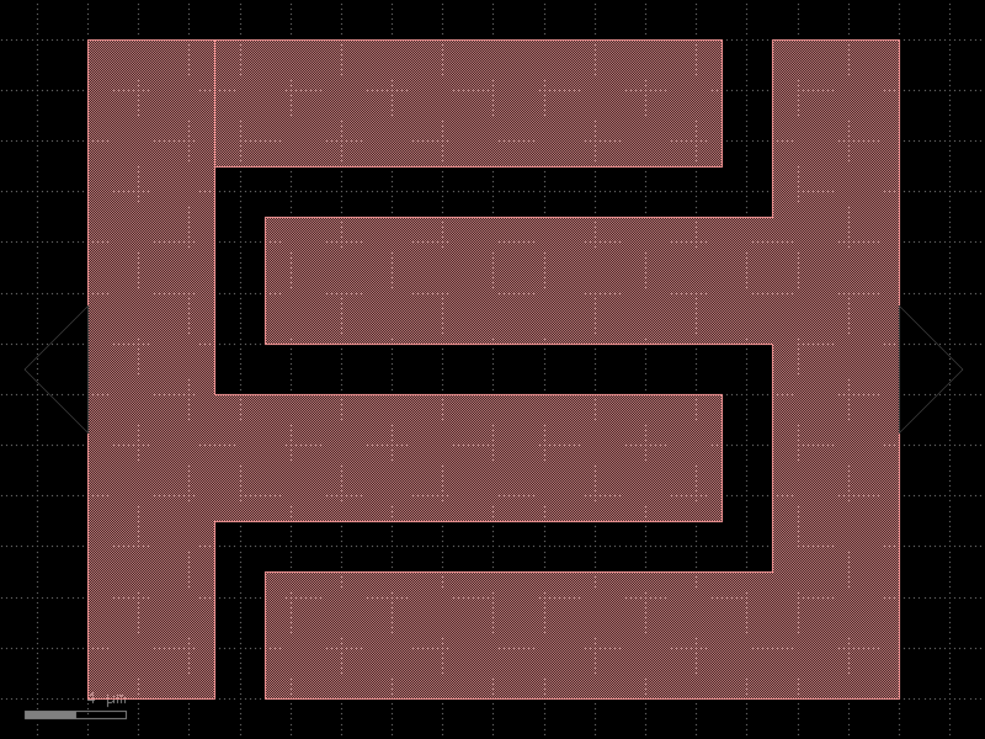
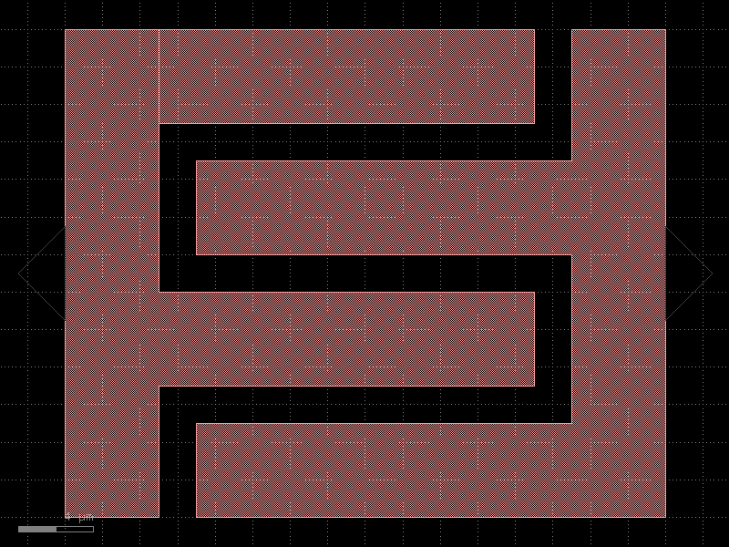
- gdsfactory.components.pads.pad_array(pad='pad', columns=6, rows=1, column_pitch=150.0, row_pitch=150.0, port_orientation=0, size=None, layer='MTOP', centered_ports=False, auto_rename_ports=False)[source]#
Returns 2D array of pads.
- Parameters:
pad (ComponentSpec) – pad element.
columns (int) – number of columns.
rows (int) – number of rows.
column_pitch (float) – x pitch.
row_pitch (float) – y pitch.
port_orientation (AngleInDegrees) – port orientation in deg. None for low speed DC ports.
size (Float2 | None) – pad size.
layer (LayerSpec | None) – pad layer.
centered_ports (bool) – True add ports to center. False add ports to the edge.
auto_rename_ports (bool) – True to auto rename ports.
- Return type:
import gdsfactory as gf

gf.gpdk.PDK.activate()

c = gf.components.pad_array(pad='pad', columns=6, rows=1, column_pitch=150, row_pitch=150, port_orientation=0, layer='MTOP', centered_ports=False, auto_rename_ports=False).copy()
c.draw_ports()
c.plot()
(Source code, png, hires.png, pdf)
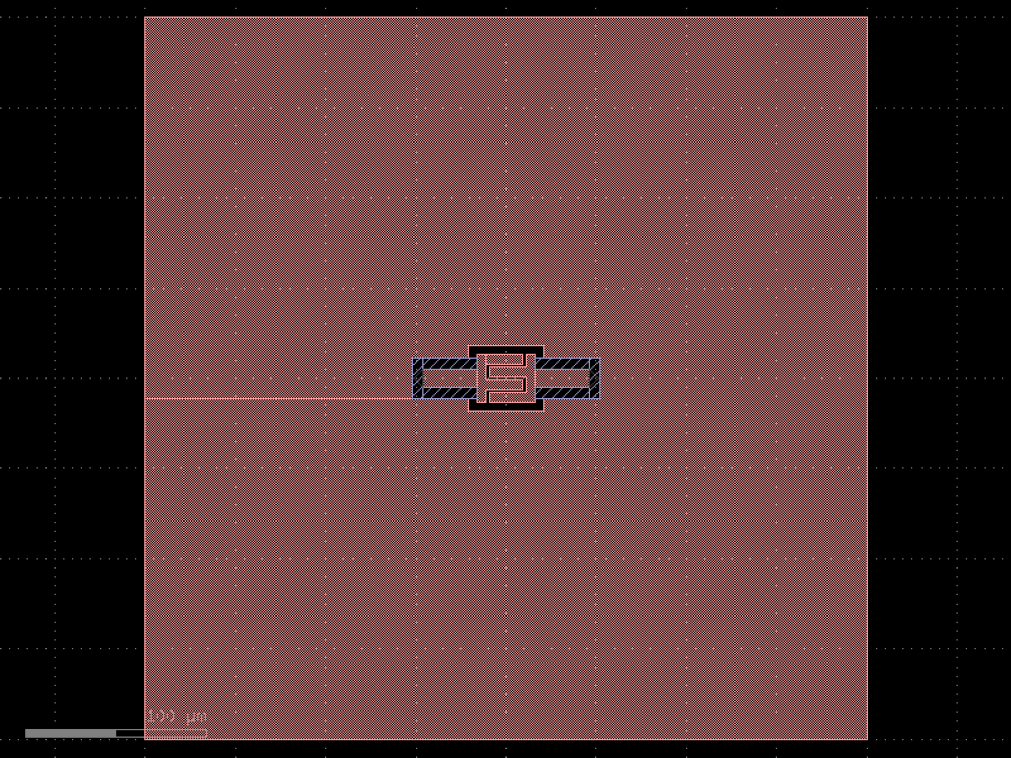
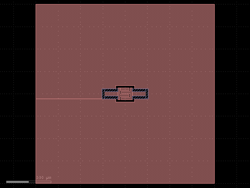
- gdsfactory.components.pads.pad_array0(pad='pad', *, columns=1, rows=3, column_pitch=150.0, row_pitch=150.0, port_orientation=0, size=None, layer='MTOP', centered_ports=False, auto_rename_ports=False)#
Returns 2D array of pads.
- Parameters:
pad (ComponentSpec) – pad element.
columns (int) – number of columns.
rows (int) – number of rows.
column_pitch (float) – x pitch.
row_pitch (float) – y pitch.
port_orientation (AngleInDegrees) – port orientation in deg. None for low speed DC ports.
size (Float2 | None) – pad size.
layer (LayerSpec | None) – pad layer.
centered_ports (bool) – True add ports to center. False add ports to the edge.
auto_rename_ports (bool) – True to auto rename ports.
- Return type:
import gdsfactory as gf

gf.gpdk.PDK.activate()

c = gf.components.pad_array0(pad='pad', columns=1, rows=3, column_pitch=150, row_pitch=150, port_orientation=0, layer='MTOP', centered_ports=False, auto_rename_ports=False).copy()
c.draw_ports()
c.plot()
(Source code, png, hires.png, pdf)
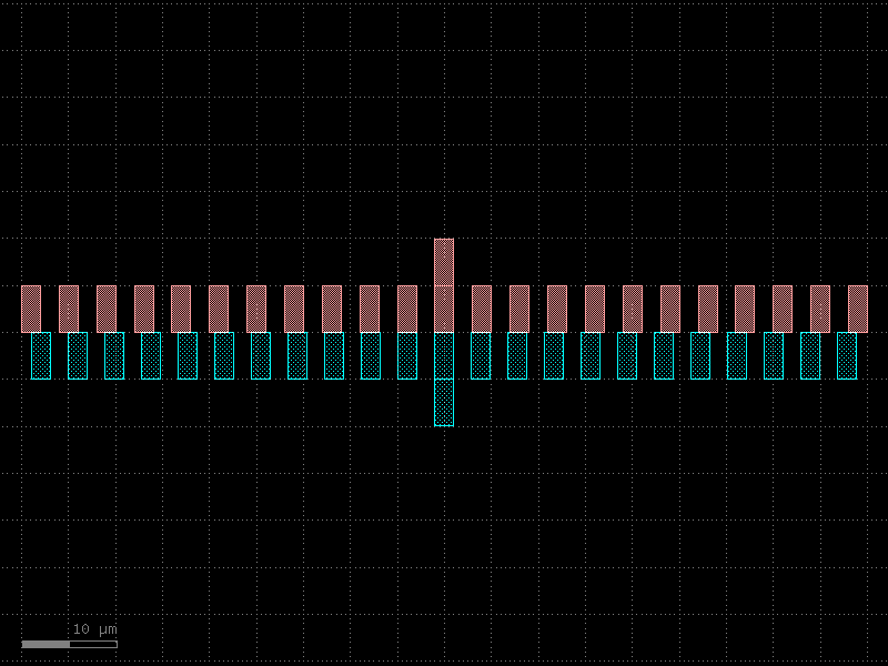
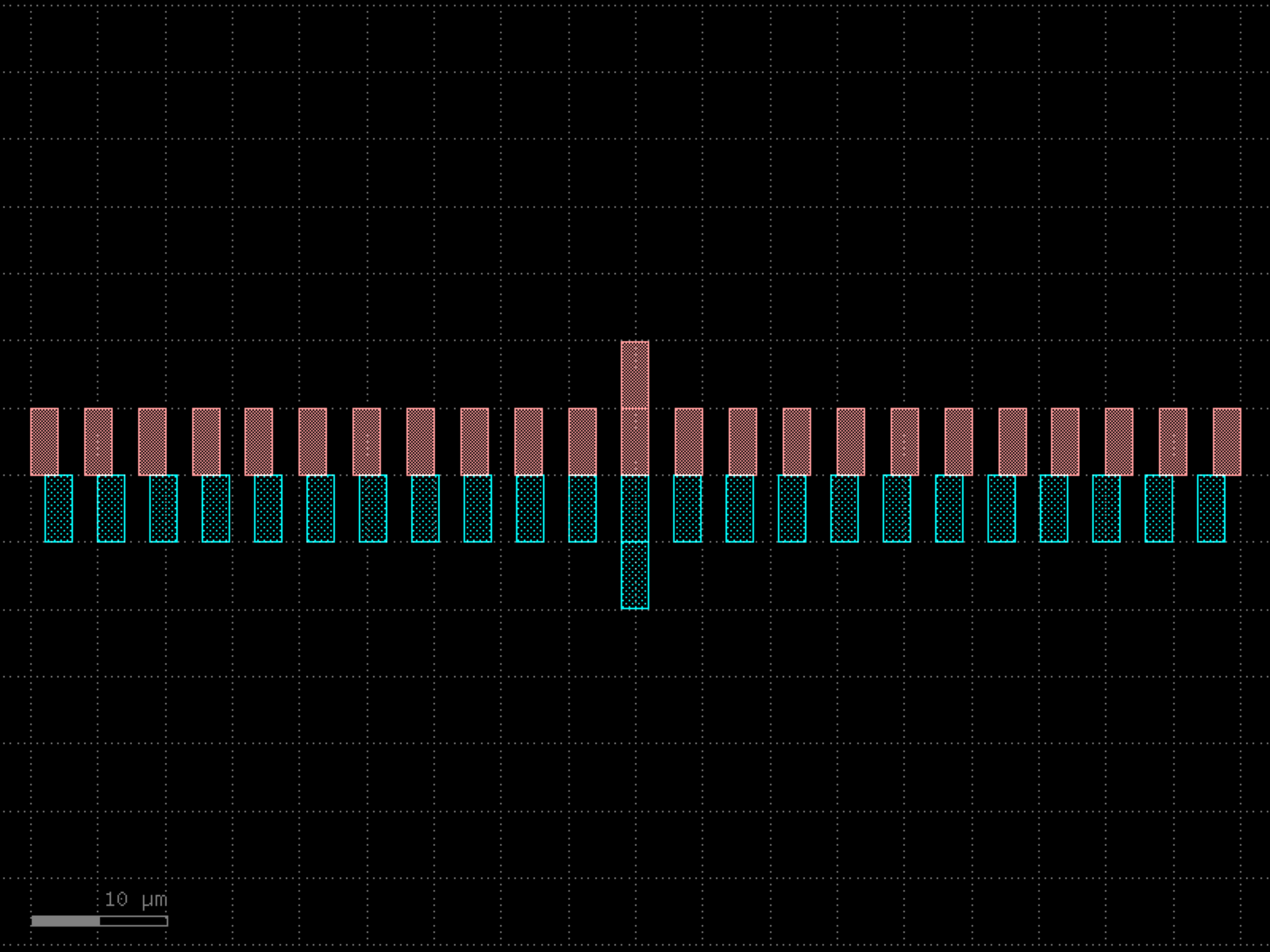

- gdsfactory.components.pads.pad_array180(pad='pad', *, columns=1, rows=3, column_pitch=150.0, row_pitch=150.0, port_orientation=180, size=None, layer='MTOP', centered_ports=False, auto_rename_ports=False)#
Returns 2D array of pads.
- Parameters:
pad (ComponentSpec) – pad element.
columns (int) – number of columns.
rows (int) – number of rows.
column_pitch (float) – x pitch.
row_pitch (float) – y pitch.
port_orientation (AngleInDegrees) – port orientation in deg. None for low speed DC ports.
size (Float2 | None) – pad size.
layer (LayerSpec | None) – pad layer.
centered_ports (bool) – True add ports to center. False add ports to the edge.
auto_rename_ports (bool) – True to auto rename ports.
- Return type:
import gdsfactory as gf

gf.gpdk.PDK.activate()

c = gf.components.pad_array180(pad='pad', columns=1, rows=3, column_pitch=150, row_pitch=150, port_orientation=180, layer='MTOP', centered_ports=False, auto_rename_ports=False).copy()
c.draw_ports()
c.plot()
(Source code, png, hires.png, pdf)
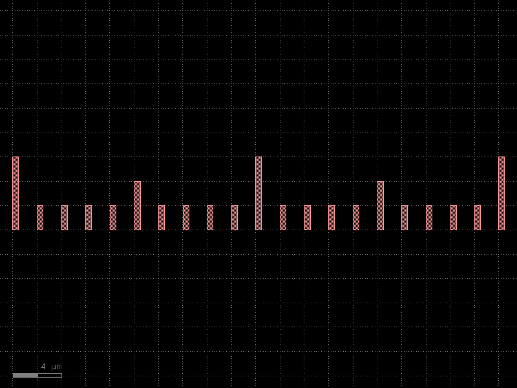
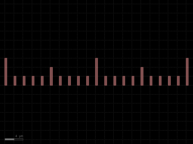
- gdsfactory.components.pads.pad_array270(pad='pad', columns=6, rows=1, column_pitch=150.0, row_pitch=150.0, *, port_orientation=270, size=None, layer='MTOP', centered_ports=False, auto_rename_ports=False)#
Returns 2D array of pads.
- Parameters:
pad (ComponentSpec) – pad element.
columns (int) – number of columns.
rows (int) – number of rows.
column_pitch (float) – x pitch.
row_pitch (float) – y pitch.
port_orientation (AngleInDegrees) – port orientation in deg. None for low speed DC ports.
size (Float2 | None) – pad size.
layer (LayerSpec | None) – pad layer.
centered_ports (bool) – True add ports to center. False add ports to the edge.
auto_rename_ports (bool) – True to auto rename ports.
- Return type:
import gdsfactory as gf

gf.gpdk.PDK.activate()

c = gf.components.pad_array270(pad='pad', columns=6, rows=1, column_pitch=150, row_pitch=150, port_orientation=270, layer='MTOP', centered_ports=False, auto_rename_ports=False).copy()
c.draw_ports()
c.plot()
(Source code, png, hires.png, pdf)
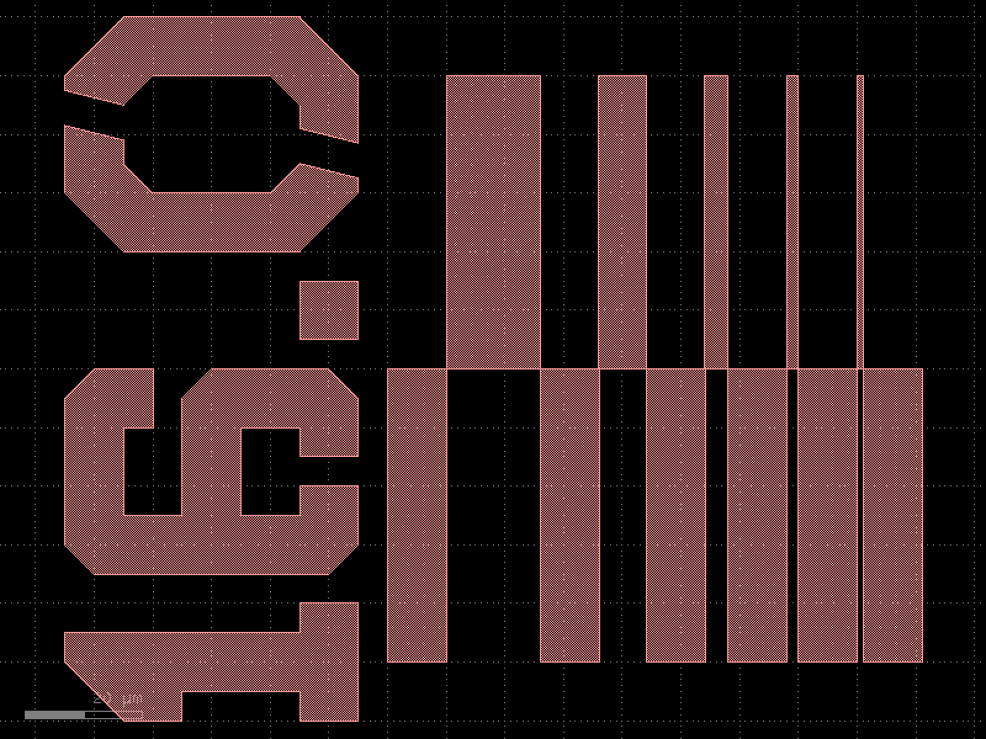

- gdsfactory.components.pads.pad_array90(pad='pad', columns=6, rows=1, column_pitch=150.0, row_pitch=150.0, *, port_orientation=90, size=None, layer='MTOP', centered_ports=False, auto_rename_ports=False)#
Returns 2D array of pads.
- Parameters:
pad (ComponentSpec) – pad element.
columns (int) – number of columns.
rows (int) – number of rows.
column_pitch (float) – x pitch.
row_pitch (float) – y pitch.
port_orientation (AngleInDegrees) – port orientation in deg. None for low speed DC ports.
size (Float2 | None) – pad size.
layer (LayerSpec | None) – pad layer.
centered_ports (bool) – True add ports to center. False add ports to the edge.
auto_rename_ports (bool) – True to auto rename ports.
- Return type:
import gdsfactory as gf

gf.gpdk.PDK.activate()

c = gf.components.pad_array90(pad='pad', columns=6, rows=1, column_pitch=150, row_pitch=150, port_orientation=90, layer='MTOP', centered_ports=False, auto_rename_ports=False).copy()
c.draw_ports()
c.plot()
(Source code, png, hires.png, pdf)
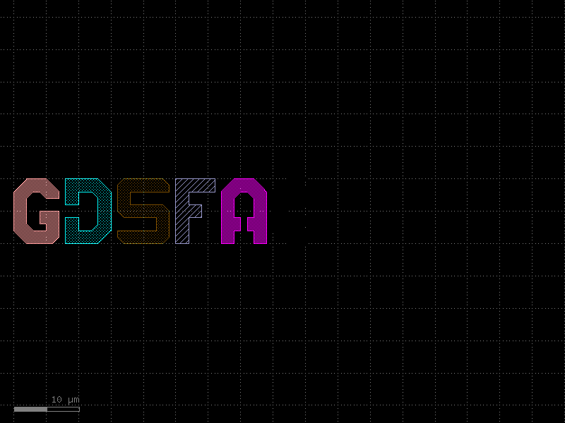

- gdsfactory.components.pads.pad_gs(length=100, cross_section='gs')[source]#
- Parameters:
length (float)
cross_section (str)
- Return type:
import gdsfactory as gf

gf.gpdk.PDK.activate()

c = gf.components.pad_gs(length=100, cross_section='gs').copy()
c.draw_ports()
c.plot()
(Source code, png, hires.png, pdf)
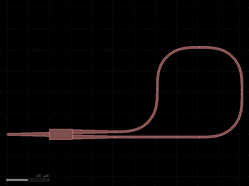

- gdsfactory.components.pads.pad_gsg(length=100, cross_section='gsg')[source]#
- Parameters:
length (float)
cross_section (str)
- Return type:
import gdsfactory as gf

gf.gpdk.PDK.activate()

c = gf.components.pad_gsg(length=100, cross_section='gsg').copy()
c.draw_ports()
c.plot()
(Source code, png, hires.png, pdf)
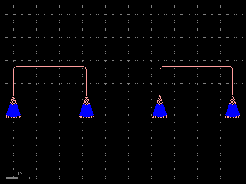
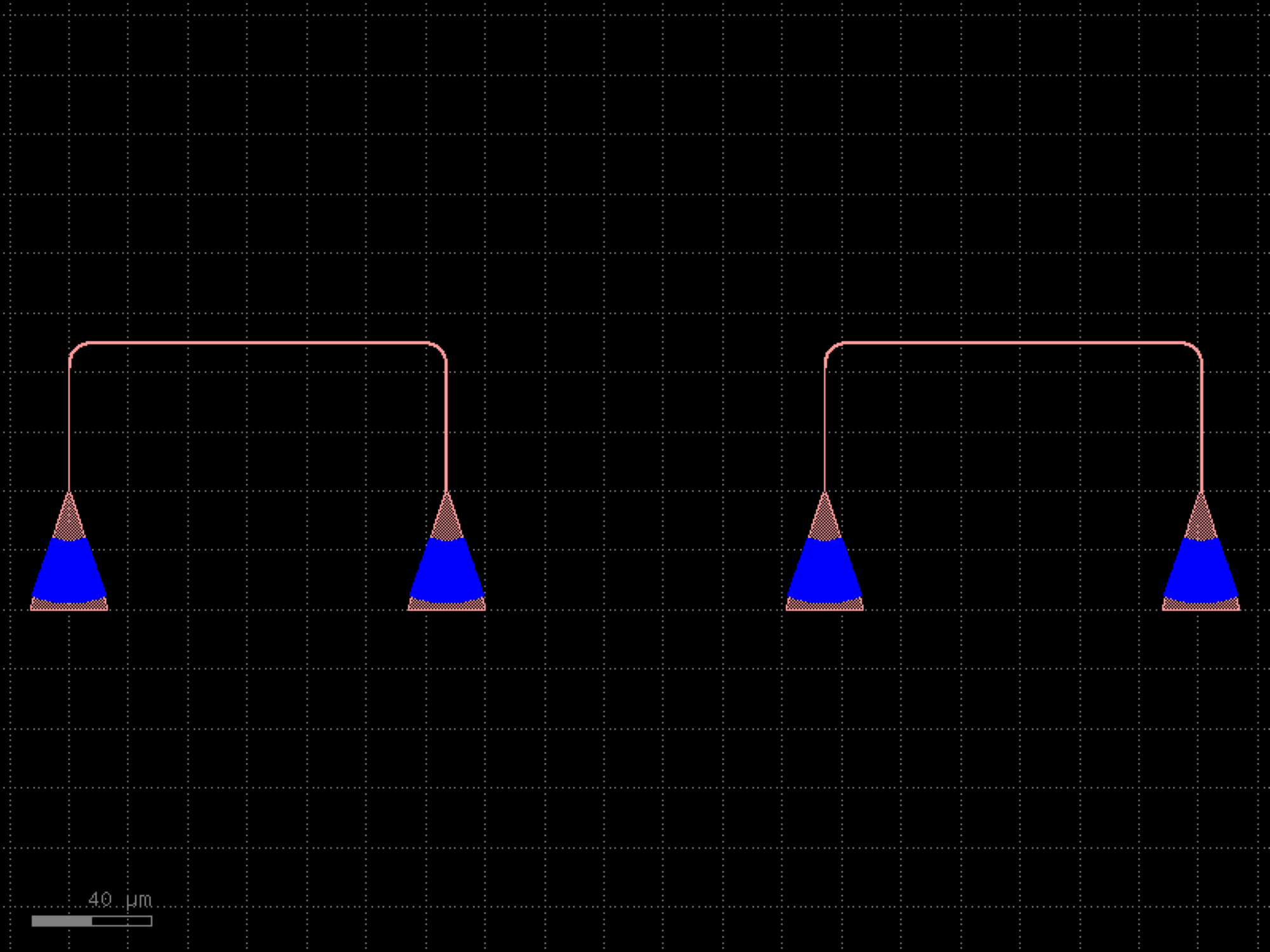

- gdsfactory.components.pads.pad_gsg_open(size=(22, 7), layer_metal='MTOP', metal_spacing=5.0, *, short=False, pad='pad', pad_pitch=150, route_xsize=50)#
Returns high speed GSG pads for calibrating the RF probes.
- Parameters:
size (Float2) – for the short.
layer_metal (LayerSpec) – for the short.
metal_spacing (float) – in um.
short (bool) – if False returns an open.
pad (ComponentSpec) – function for pad.
pad_pitch (float) – in um.
route_xsize (float) – in um.
- Return type:
gf.Component
import gdsfactory as gf

gf.gpdk.PDK.activate()

c = gf.components.pad_gsg_open(size=(22, 7), layer_metal='MTOP', metal_spacing=5, short=False, pad='pad', pad_pitch=150, route_xsize=50).copy()
c.draw_ports()
c.plot()
(Source code, png, hires.png, pdf)
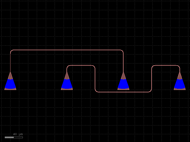
- gdsfactory.components.pads.pad_gsg_short(size=(22, 7), layer_metal='MTOP', metal_spacing=5.0, short=True, pad='pad', pad_pitch=150, route_xsize=50)[source]#
Returns high speed GSG pads for calibrating the RF probes.
- Parameters:
size (tuple[float, float]) – for the short.
layer_metal (LayerSpec) – for the short.
metal_spacing (float) – in um.
short (bool) – if False returns an open.
pad (ComponentSpec) – function for pad.
pad_pitch (float) – in um.
route_xsize (float) – in um.
- Return type:
import gdsfactory as gf

gf.gpdk.PDK.activate()

c = gf.components.pad_gsg_short(size=(22, 7), layer_metal='MTOP', metal_spacing=5, short=True, pad='pad', pad_pitch=150, route_xsize=50).copy()
c.draw_ports()
c.plot()
(Source code, png, hires.png, pdf)
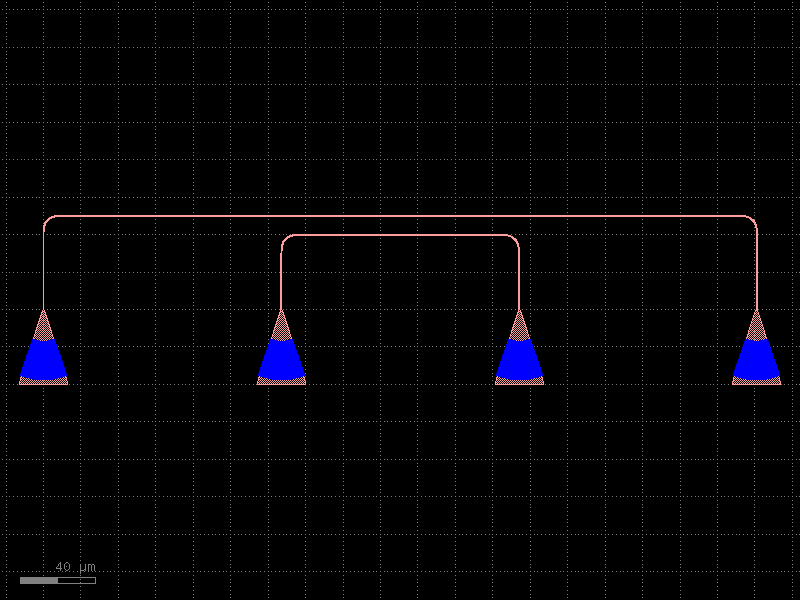

- gdsfactory.components.pads.pad_rectangular(*, size='pad_size', layer='MTOP', bbox_layers=None, bbox_offsets=None, port_inclusion=0, port_orientation=0, port_orientations=(180, 90, 0, -90), port_type='pad')#
Returns rectangular pad with ports.
- Parameters:
size (Size | str) – x, y size.
layer (LayerSpec) – pad layer.
bbox_layers (tuple[LayerSpec, ...] | None) – list of layers.
bbox_offsets (tuple[float, ...] | None) – Optional offsets for each layer with respect to size. positive grows, negative shrinks the size.
port_inclusion (float) – from edge.
port_orientation (AngleInDegrees | None) – in degrees for the center port.
port_orientations (Ints | None) – list of port_orientations to add. None does not add ports.
port_type (str) – port type for pad port.
- Return type:
import gdsfactory as gf

gf.gpdk.PDK.activate()

c = gf.components.pad_rectangular(size='pad_size', layer='MTOP', port_inclusion=0, port_orientation=0, port_orientations=(180, 90, 0, -90), port_type='pad').copy()
c.draw_ports()
c.plot()
(Source code, png, hires.png, pdf)
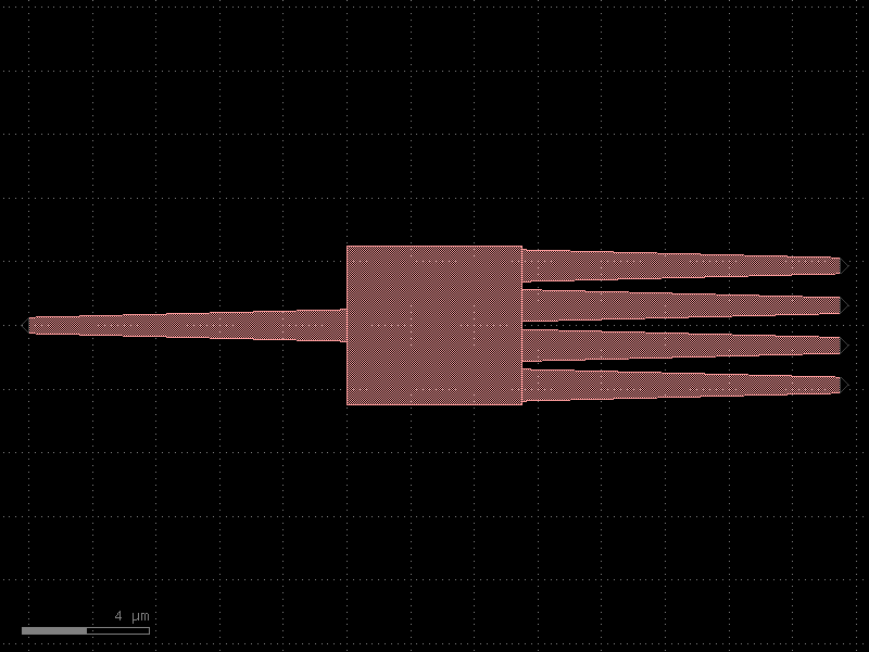
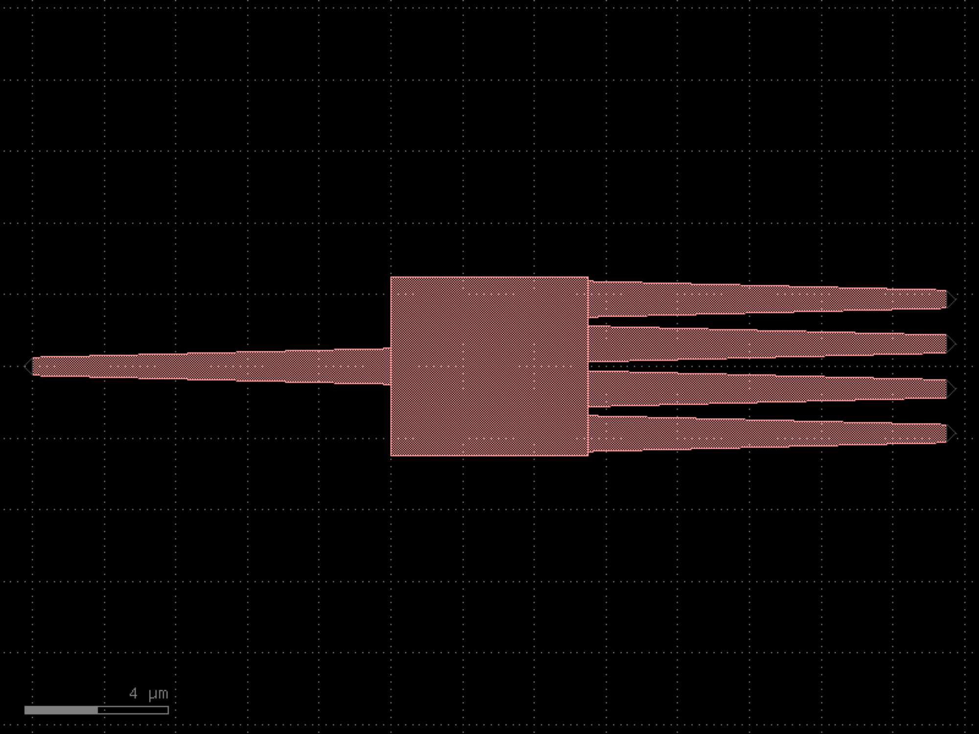

- gdsfactory.components.pads.pad_small(*, size=(80, 80), layer='MTOP', bbox_layers=None, bbox_offsets=None, port_inclusion=0, port_orientation=0, port_orientations=(180, 90, 0, -90), port_type='pad')#
Returns rectangular pad with ports.
- Parameters:
size (Size | str) – x, y size.
layer (LayerSpec) – pad layer.
bbox_layers (tuple[LayerSpec, ...] | None) – list of layers.
bbox_offsets (tuple[float, ...] | None) – Optional offsets for each layer with respect to size. positive grows, negative shrinks the size.
port_inclusion (float) – from edge.
port_orientation (AngleInDegrees | None) – in degrees for the center port.
port_orientations (Ints | None) – list of port_orientations to add. None does not add ports.
port_type (str) – port type for pad port.
- Return type:
import gdsfactory as gf

gf.gpdk.PDK.activate()

c = gf.components.pad_small(size=(80, 80), layer='MTOP', port_inclusion=0, port_orientation=0, port_orientations=(180, 90, 0, -90), port_type='pad').copy()
c.draw_ports()
c.plot()
(Source code, png, hires.png, pdf)
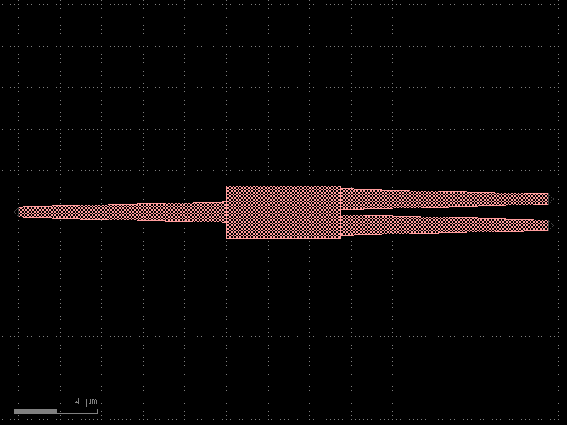

- gdsfactory.components.pads.pads_shorted(pad='pad', columns=8, pad_pitch=150.0, layer_metal='MTOP', metal_width=10)[source]#
Returns a 1D array of shorted_pads.
- Parameters:
pad (ComponentSpec) – pad spec.
columns (int) – number of columns.
pad_pitch (float) – in um
layer_metal (LayerSpec) – for the short.
metal_width (float) – for the short.
- Return type:
import gdsfactory as gf

gf.gpdk.PDK.activate()

c = gf.components.pads_shorted(pad='pad', columns=8, pad_pitch=150, layer_metal='MTOP', metal_width=10).copy()
c.draw_ports()
c.plot()
(Source code, png, hires.png, pdf)
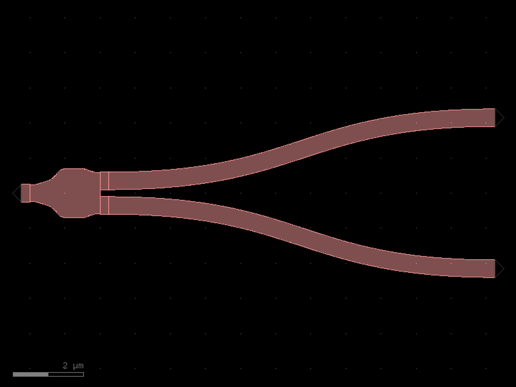
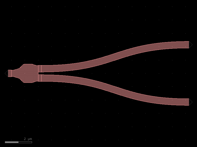
- gdsfactory.components.pads.rectangle_with_slits(size=(100.0, 200.0), layer='WG', layer_slit=None, centered=False, port_type=None, slit_size=(1.0, 1.0), slit_column_pitch=20, slit_row_pitch=20, slit_enclosure=10)[source]#
Returns a rectangle with slits.
Metal slits reduce stress.
- Parameters:
size (Size) – (tuple) Width and height of rectangle.
layer (LayerSpec) – Specific layer to put polygon geometry on.
layer_slit (LayerSpec | None) – does a boolean NOT when None.
centered (bool) – True sets center to (0, 0), False sets south-west to (0, 0)
port_type (str | None) – for the rectangle.
slit_size (Size) – x, y slit size.
slit_column_pitch (float) – pitch for columns of slits.
slit_row_pitch (float) – pitch for rows of slits.
slit_enclosure (float) – from slit to rectangle edge.
- Return type:
slit_enclosure
_____________________________________
|<--->                              |
|                                   |
|      ______________________       |
|     |                      |      |
|     |                      | slit_size[1]
|  _  |______________________|      |
|  |                                |
|  | slit_row_pitch                 |
|  |                                |  size[1]
|  |   ______________________       |
|  |  |                      |      |
|  |  |                      |      |
|  _  |______________________|      |
|     <--------------------->       |
|            slit_size[0]           |
|___________________________________|
                size[0]
import gdsfactory as gf

gf.gpdk.PDK.activate()

c = gf.components.rectangle_with_slits(size=(100, 200), layer='WG', centered=False, slit_size=(1, 1), slit_column_pitch=20, slit_row_pitch=20, slit_enclosure=10).copy()
c.draw_ports()
c.plot()
(Source code, png, hires.png, pdf)
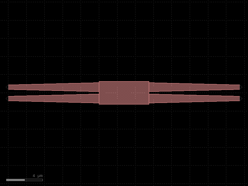

pcms#
- gdsfactory.components.pcms.alignment_mark_cross(arm_width=2.0, arm_length=20.0, layer='WG', port_type=None)[source]#
Custom alignment cross mark for lithography alignment.
Creates a cross shape centered at the origin composed of two overlapping rectangles (horizontal and vertical arms).
- Parameters:
arm_width (float) – Width of each arm in um.
arm_length (float) – Length of each arm in um (full extent from tip to tip is 2 * arm_length).
layer (LayerSpec) – Layer specification for the cross geometry.
port_type (str | None) – Optional port type. If provided, ports are added at the four arm tips.
- Return type:
import gdsfactory as gf

gf.gpdk.PDK.activate()

c = gf.components.alignment_mark_cross(arm_width=2, arm_length=20, layer='WG').copy()
c.draw_ports()
c.plot()
(Source code, png, hires.png, pdf)
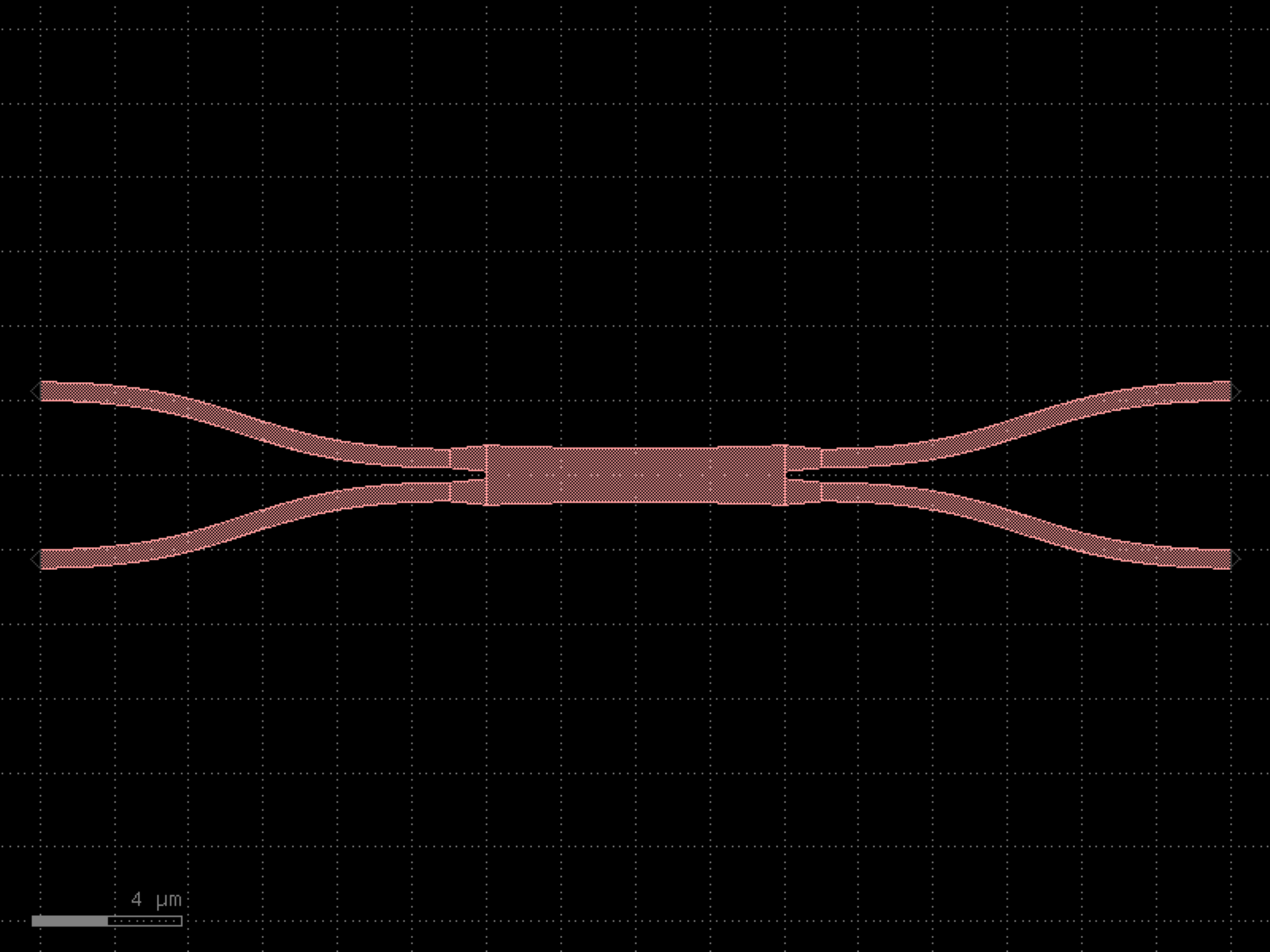
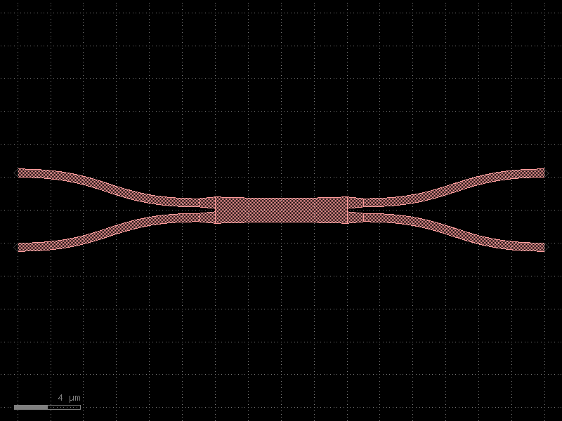
- gdsfactory.components.pcms.cavity(component='dbr', coupler='coupler', length=0.1, gap=0.2, **kwargs)[source]#
Returns cavity from a coupler and a mirror.
connects the W0 port of the mirror to E1 and W1 coupler ports creating a resonant cavity
- Parameters:
component (ComponentSpec) – mirror.
coupler (ComponentSpec) – coupler library.
length (float) – coupler length.
gap (float) – coupler gap.
kwargs (Any) – coupler_settings.
- Return type:
ml (mirror left)              mr (mirror right)
 |                               |
 |o1 - o2__             __o3 - o1|
 |         \           /         |
            \         /
          ---=========---
   o1  o1    length      o4    o2
import gdsfactory as gf

gf.gpdk.PDK.activate()

c = gf.components.cavity(component='dbr', coupler='coupler', length=0.1, gap=0.2).copy()
c.draw_ports()
c.plot()
(Source code, png, hires.png, pdf)
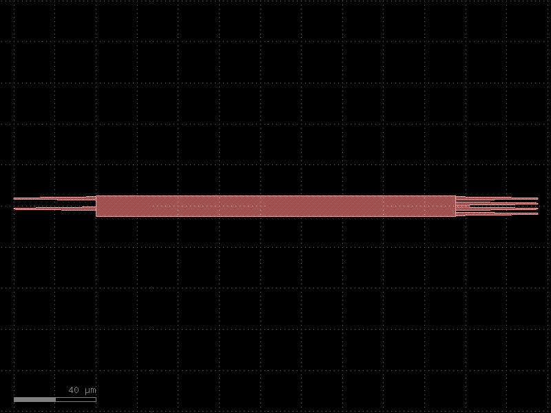
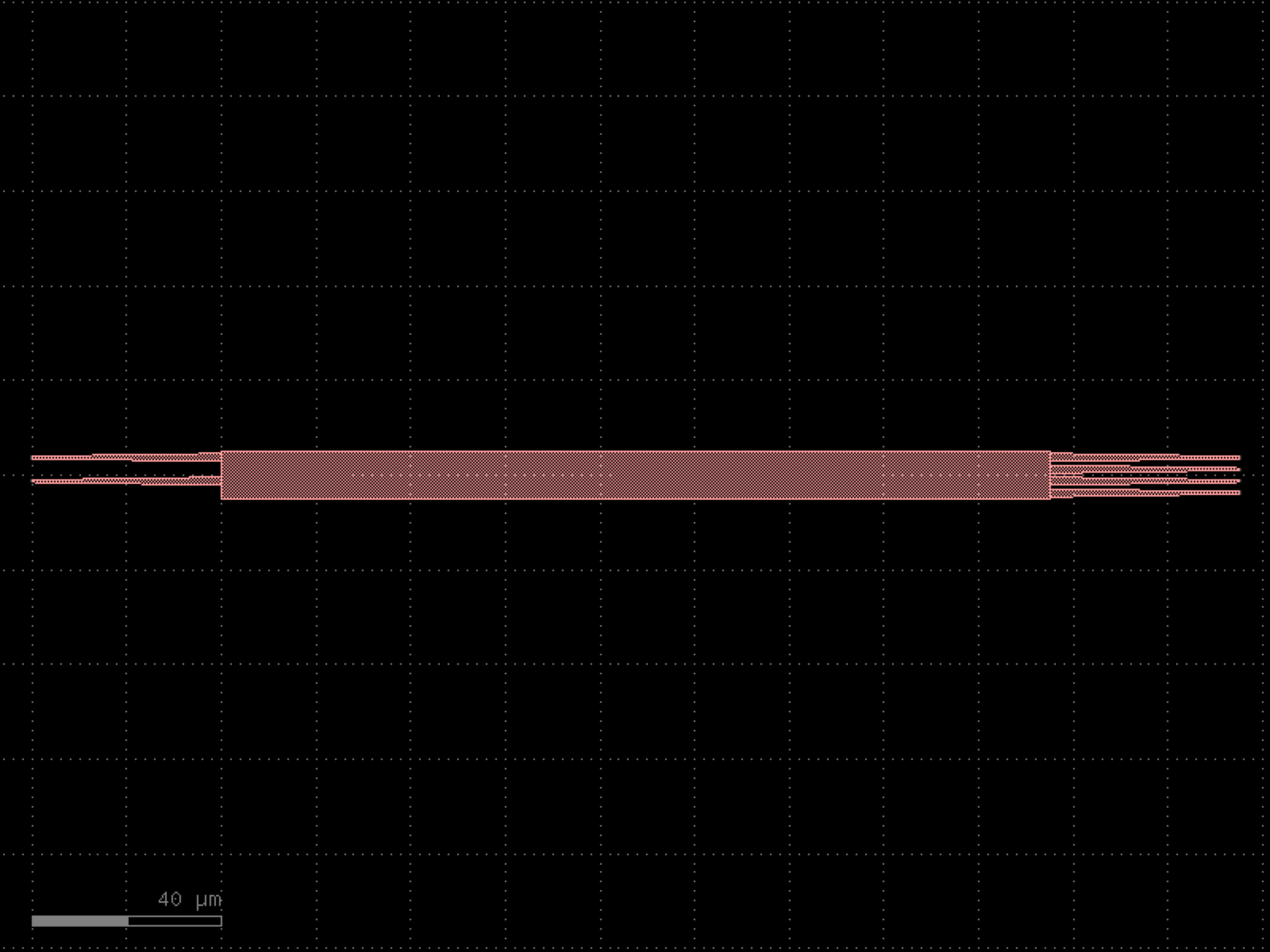

- gdsfactory.components.pcms.cdsem_all(widths=(0.4, 0.45, 0.5, 0.6, 0.8, 1.0), dense_lines_width=0.3, dense_lines_width_difference=0.02, dense_lines_gap=0.3, dense_lines_labels=('DL', 'DM', 'DH'), straight='straight', bend90='bend_circular', cross_section='strip', text='text_rectangular', spacing=5, cdsem_bend180='cdsem_bend180', text_size=1)[source]#
Column with all optical PCMs.
- Parameters:
widths (tuple[float, ...]) – for straight lines.
dense_lines_width (float | None) – in um.
dense_lines_width_difference (float) – in um.
dense_lines_gap (float) – in um.
dense_lines_labels (tuple[str, ...]) – strings.
straight (ComponentSpec) – spec.
bend90 (ComponentSpec | None) – spec.
cross_section (CrossSectionSpec) – spec.
text (ComponentSpec) – spec.
spacing (float) – from group to group.
cdsem_bend180 (ComponentSpec) – spec.
text_size (float) – in um.
- Return type:
import gdsfactory as gf

gf.gpdk.PDK.activate()

c = gf.components.cdsem_all(widths=(0.4, 0.45, 0.5, 0.6, 0.8, 1), dense_lines_width=0.3, dense_lines_width_difference=0.02, dense_lines_gap=0.3, dense_lines_labels=('DL', 'DM', 'DH'), straight='straight', bend90='bend_circular', cross_section='strip', text='text_rectangular', spacing=5, cdsem_bend180='cdsem_bend180', text_size=1).copy()
c.draw_ports()
c.plot()
(Source code, png, hires.png, pdf)
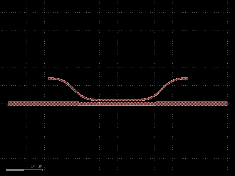
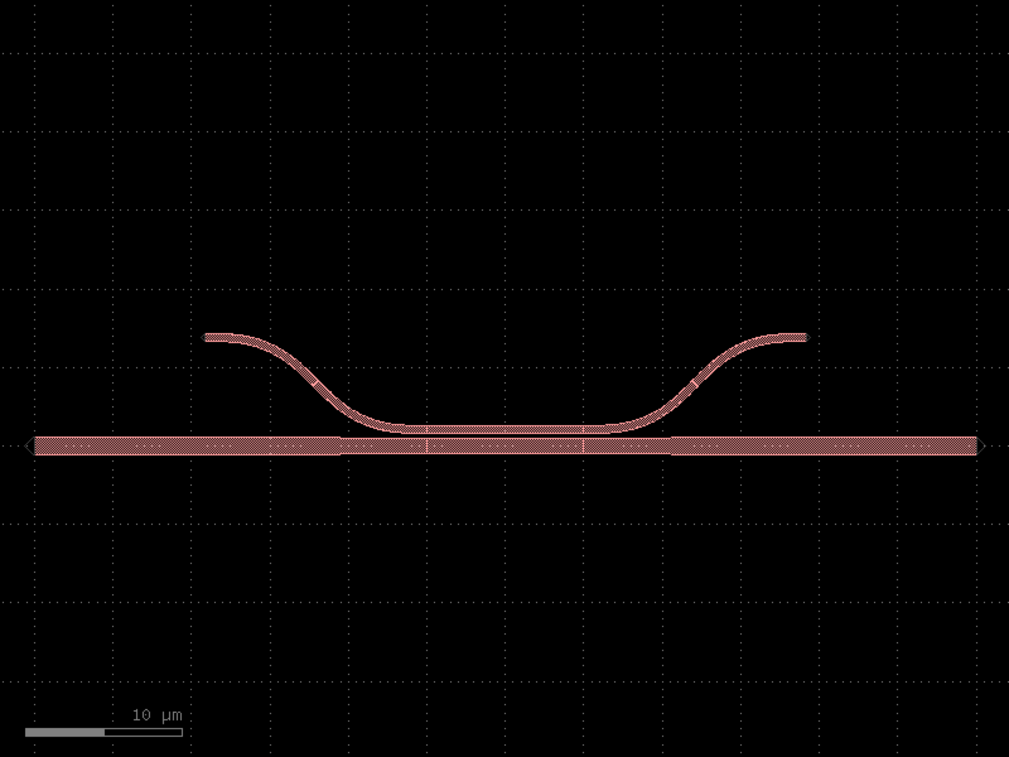

- gdsfactory.components.pcms.cdsem_bend180(width=0.5, radius=10.0, wg_length=420.0, straight='straight', bend90='bend_circular', cross_section='strip', text='text_rectangular', text_size=1.0)[source]#
Returns CDSEM structures.
- Parameters:
width (float) – of the line.
radius (float) – um.
wg_length (float | None) – in um.
straight (ComponentSpec) – spec.
bend90 (ComponentSpec) – spec.
cross_section (CrossSectionSpec) – spec.
text (ComponentSpec) – spec.
text_size (float) – um.
- Return type:
import gdsfactory as gf

gf.gpdk.PDK.activate()

c = gf.components.cdsem_bend180(width=0.5, radius=10, wg_length=420, straight='straight', bend90='bend_circular', cross_section='strip', text='text_rectangular', text_size=1).copy()
c.draw_ports()
c.plot()
(Source code, png, hires.png, pdf)
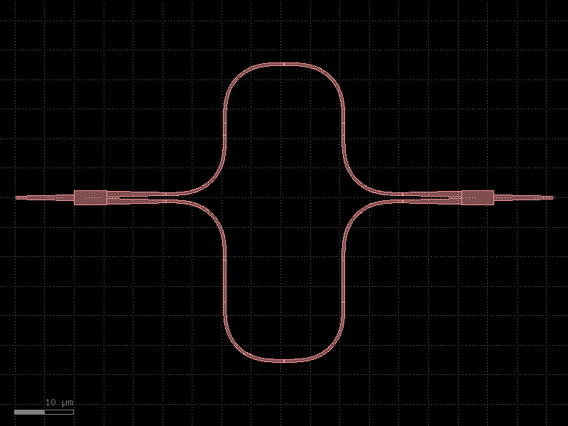
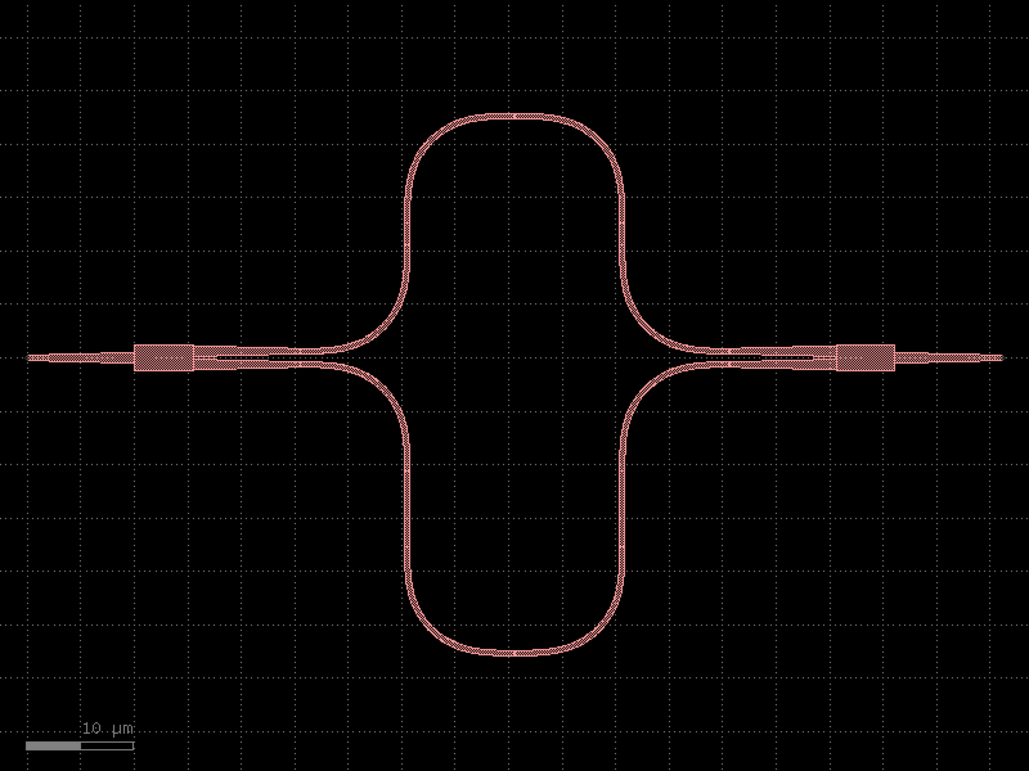

- gdsfactory.components.pcms.cdsem_coupler(length=420.0, gaps=(0.15, 0.2, 0.25), cross_section='strip_no_ports', text='text_rectangular', spacing=7.0, positions=None, width=None, text_size=1.0)[source]#
Returns 2 coupled waveguides gap sweep.
- Parameters:
length (float) – for the line.
gaps (Sequence[float]) – list of gaps for the sweep.
cross_section (CrossSectionSpec) – for the lines.
text (ComponentSpec | None) – optional text for labels.
spacing (float) – Optional center to center spacing.
positions (Sequence[float | None] | None) – Optional positions for the text labels.
width (float | None) – width of the waveguide. If None, it will use the width of the cross_section.
text_size (float) – size of the text.
- Return type:
import gdsfactory as gf

gf.gpdk.PDK.activate()

c = gf.components.cdsem_coupler(length=420, gaps=(0.15, 0.2, 0.25), cross_section='strip_no_ports', text='text_rectangular', spacing=7, text_size=1).copy()
c.draw_ports()
c.plot()
(Source code, png, hires.png, pdf)
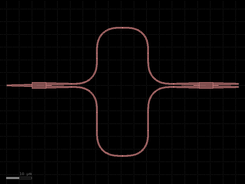

- gdsfactory.components.pcms.cdsem_straight(widths=(0.4, 0.45, 0.5, 0.6, 0.8, 1.0), length=420.0, cross_section='strip_no_ports', text='text_rectangular', spacing=7.0, positions=None, text_size=1)[source]#
Returns straight waveguide lines width sweep.
- Parameters:
widths (Sequence[float]) – for the sweep.
length (float) – for the line.
cross_section (CrossSectionSpec) – for the lines.
text (ComponentSpec | None) – optional text for labels.
spacing (float) – Optional center to center spacing.
positions (Sequence[float | None] | None) – Optional positions for the text labels.
text_size (float) – in um.
- Return type:
import gdsfactory as gf

gf.gpdk.PDK.activate()

c = gf.components.cdsem_straight(widths=(0.4, 0.45, 0.5, 0.6, 0.8, 1), length=420, cross_section='strip_no_ports', text='text_rectangular', spacing=7, text_size=1).copy()
c.draw_ports()
c.plot()
(Source code, png, hires.png, pdf)
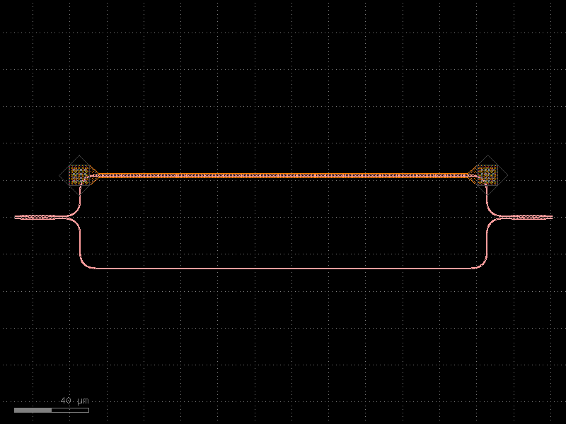
- gdsfactory.components.pcms.cdsem_straight_density(widths=(0.3, 0.3, 0.3, 0.3, 0.3, 0.3, 0.3, 0.3, 0.3, 0.3), gaps=(0.3, 0.3, 0.3, 0.3, 0.3, 0.3, 0.3, 0.3, 0.3, 0.3), length=420.0, label='', cross_section='strip_no_ports', text='text_rectangular', text_size=1.0)[source]#
Returns sweep of dense straight lines.
- Parameters:
widths (Floats) – list of widths.
gaps (Floats) – list of gaps.
length (float) – of the lines.
label (str) – defaults to widths[0] gaps[0].
cross_section (CrossSectionSpec) – spec.
text (ComponentSpec | None) – optional function for text.
text_size (float) – size of the text.
- Return type:
import gdsfactory as gf

gf.gpdk.PDK.activate()

c = gf.components.cdsem_straight_density(widths=(0.3, 0.3, 0.3, 0.3, 0.3, 0.3, 0.3, 0.3, 0.3, 0.3), gaps=(0.3, 0.3, 0.3, 0.3, 0.3, 0.3, 0.3, 0.3, 0.3, 0.3), length=420, label='', cross_section='strip_no_ports', text='text_rectangular', text_size=1).copy()
c.draw_ports()
c.plot()
(Source code, png, hires.png, pdf)
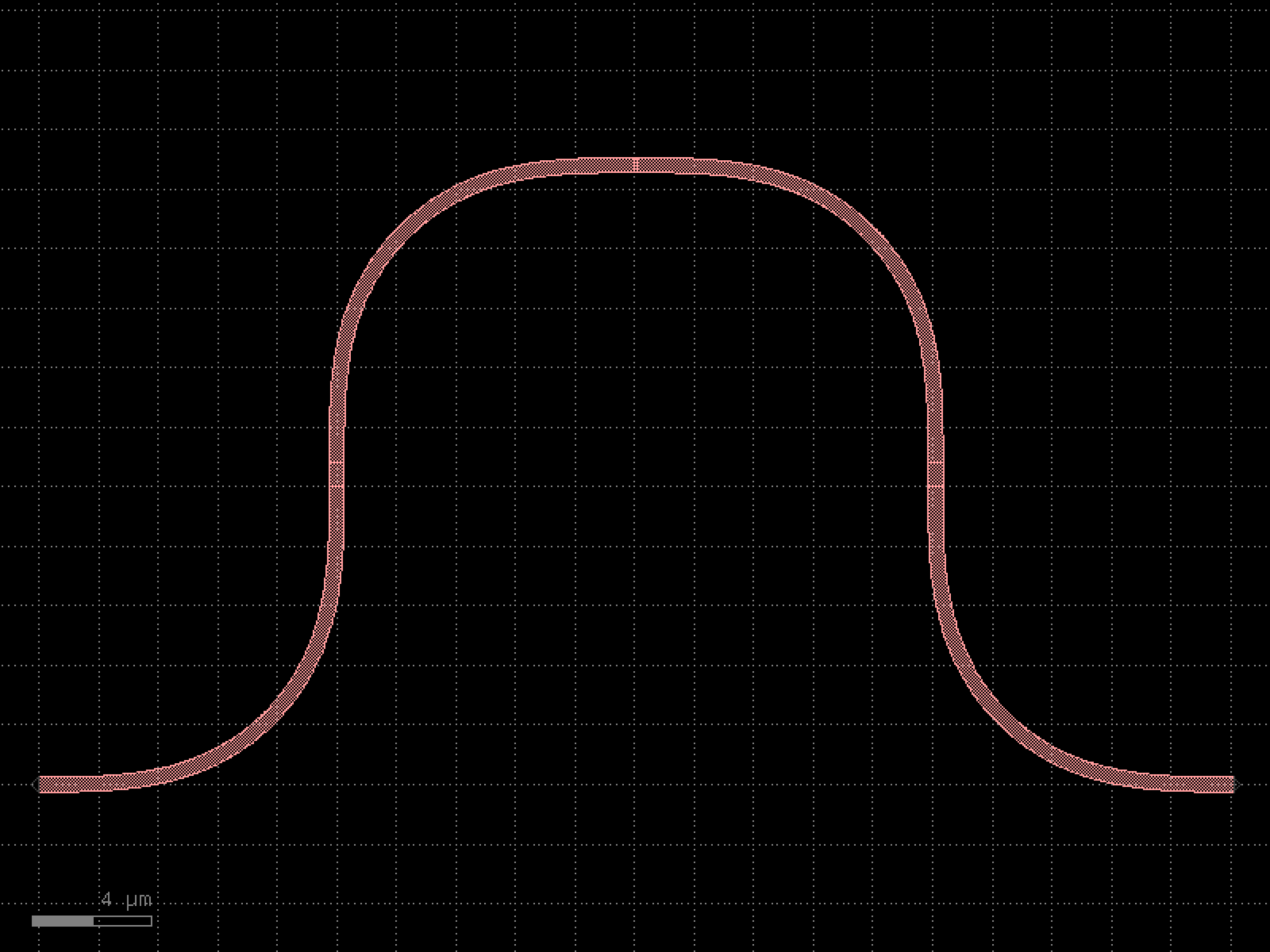
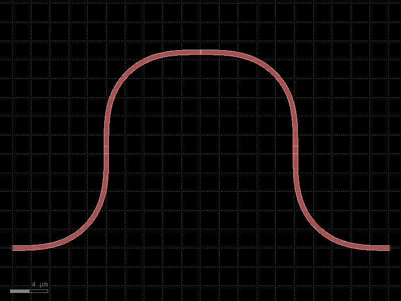
- gdsfactory.components.pcms.cutback_2x2(component='mmi2x2', cols=4, rows=5, port1='o1', port2='o2', port3='o3', port4='o4', bend180='bend_circular180', mirror=False, straight_length=None, cross_section='strip', straight='straight')[source]#
Returns a daisy chain of splitters for measuring their loss.
- Parameters:
component (ComponentSpec) – for cutback.
cols (int) – number of columns.
rows (int) – number of rows.
port1 (str) – name of first optical port.
port2 (str) – name of second optical port.
port3 (str) – name of third optical port.
port4 (str) – name of fourth optical port.
bend180 (ComponentSpec) – ubend.
mirror (bool) – Flips component. Useful when ‘o2’ is the port that you want to route to.
straight_length (float | None) – length of the straight section between cutbacks.
cross_section (CrossSectionSpec) – specification (CrossSection, string or dict).
straight (ComponentSpec) – straight spec.
- Return type:
import gdsfactory as gf

gf.gpdk.PDK.activate()

c = gf.components.cutback_2x2(component='mmi2x2', cols=4, rows=5, port1='o1', port2='o2', port3='o3', port4='o4', bend180='bend_circular180', mirror=False, cross_section='strip', straight='straight').copy()
c.draw_ports()
c.plot()
(Source code, png, hires.png, pdf)
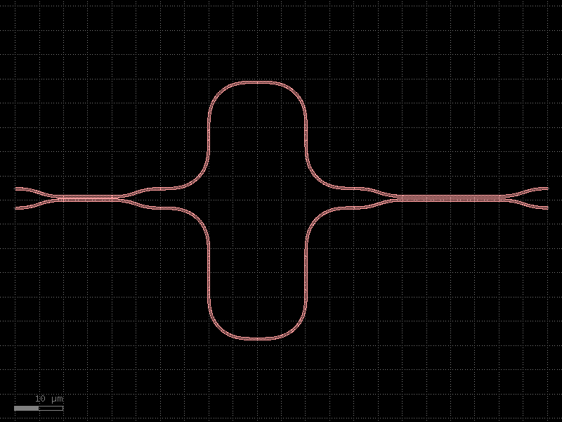

- gdsfactory.components.pcms.cutback_bend(component='bend_euler', straight='straight', straight_length=5.0, rows=6, cols=5, **kwargs)[source]#
We recommend using cutback_bend90 instead for a smaller footprint.
- Parameters:
component (ComponentSpec) – bend spec.
straight (ComponentSpec) – straight spec.
straight_length (float) – in um.
rows (int) – number of rows.
cols (int) – number of cols.
kwargs (Any) – cross_section settings.
- Return type:
this is a column
    _
  _|
_|

_ this is a row
import gdsfactory as gf

gf.gpdk.PDK.activate()

c = gf.components.cutback_bend(component='bend_euler', straight='straight', straight_length=5, rows=6, cols=5).copy()
c.draw_ports()
c.plot()
(Source code, png, hires.png, pdf)
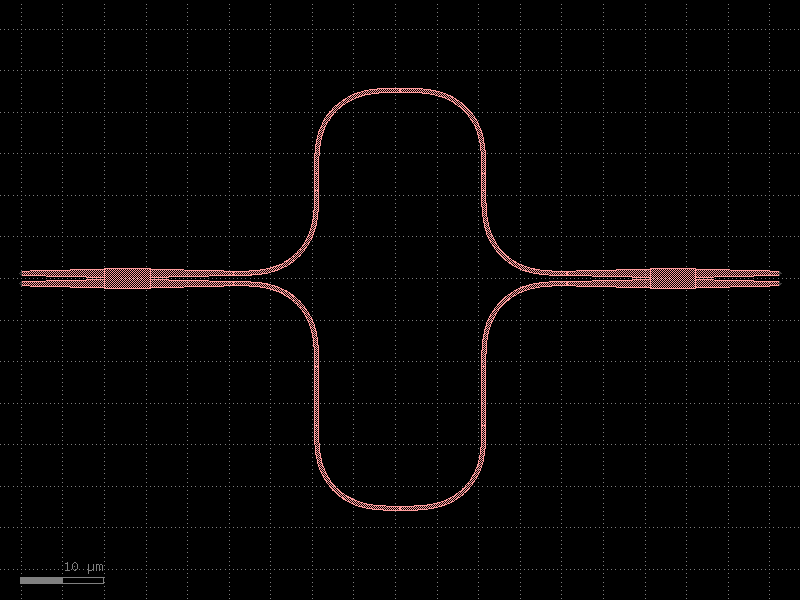
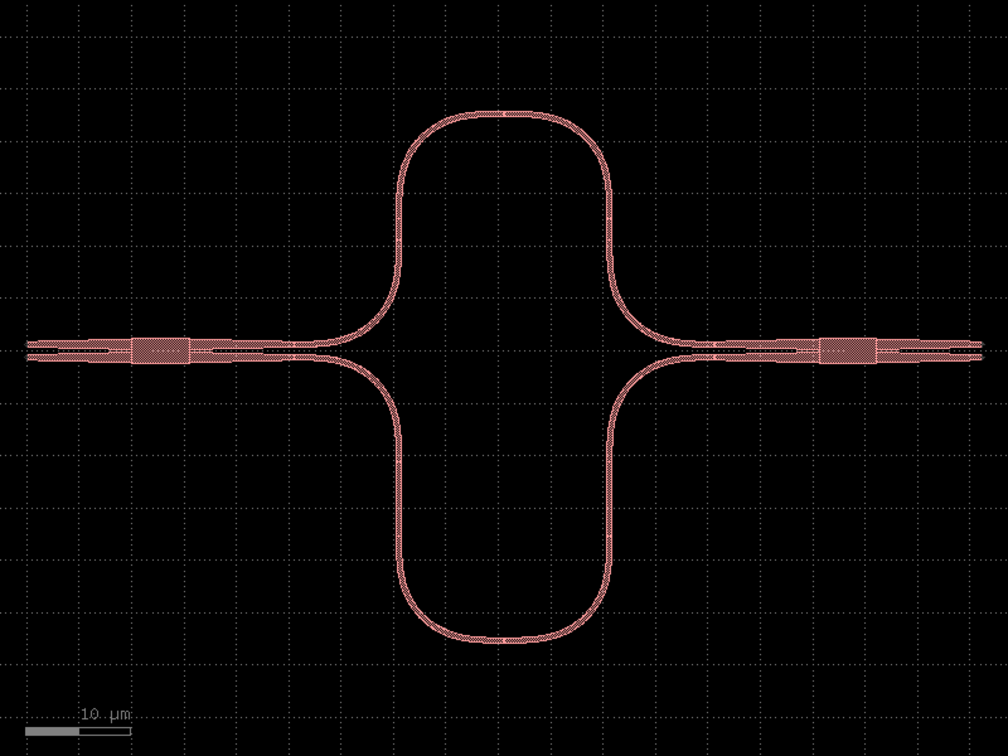

- gdsfactory.components.pcms.cutback_bend180(component='bend_euler180', straight='straight', straight_length=5.0, rows=6, cols=6, spacing=3.0, **kwargs)[source]#
Returns cutback to measure u bend loss.
- Parameters:
component (ComponentSpec) – bend spec.
straight (ComponentSpec) – straight spec.
straight_length (float) – in um.
rows (int) – number of rows.
cols (int) – number of cols.
spacing (float) – in um.
kwargs (Any) – cross_section settings.
- Return type:
  _
_| |_  this is a row

_ this is a column
import gdsfactory as gf

gf.gpdk.PDK.activate()

c = gf.components.cutback_bend180(component='bend_euler180', straight='straight', straight_length=5, rows=6, cols=6, spacing=3).copy()
c.draw_ports()
c.plot()
(Source code, png, hires.png, pdf)
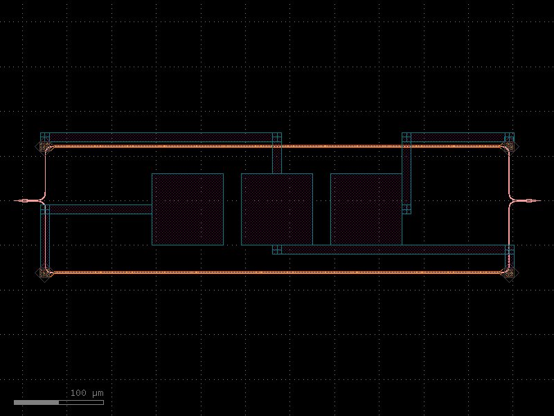

- gdsfactory.components.pcms.cutback_bend180circular(*, component='bend_circular180', straight='straight', straight_length=5.0, rows=6, cols=6, spacing=3.0, **kwargs)#
Returns cutback to measure u bend loss.
- Parameters:
component (ComponentSpec) – bend spec.
straight (ComponentSpec) – straight spec.
straight_length (float) – in um.
rows (int) – number of rows.
cols (int) – number of cols.
spacing (float) – in um.
kwargs (Any) – cross_section settings.
- Return type:
  _
_| |_  this is a row

_ this is a column
import gdsfactory as gf

gf.gpdk.PDK.activate()

c = gf.components.cutback_bend180circular(component='bend_circular180', straight='straight', straight_length=5, rows=6, cols=6, spacing=3).copy()
c.draw_ports()
c.plot()
(Source code, png, hires.png, pdf)
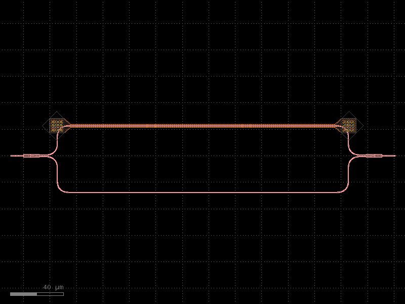
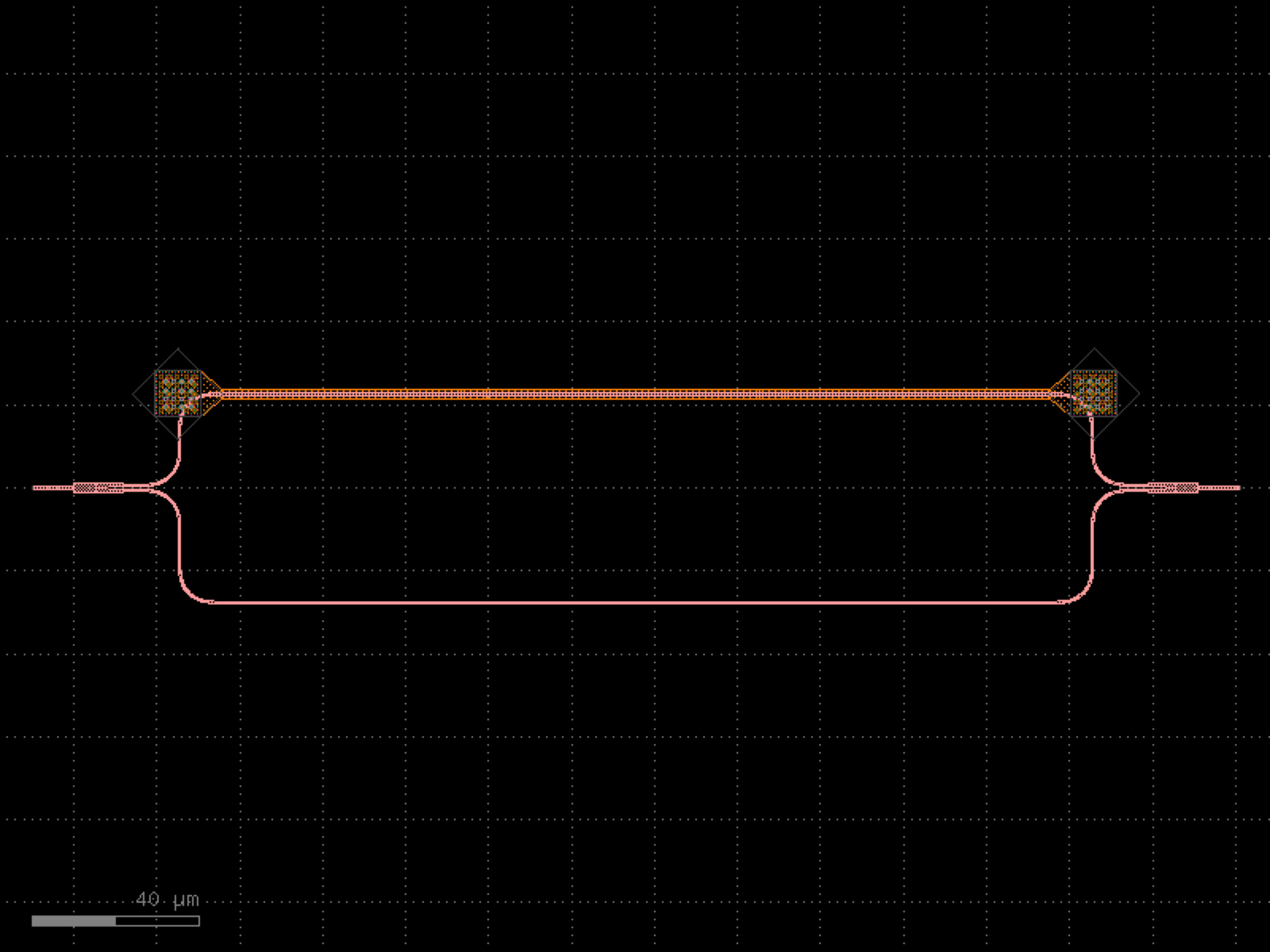
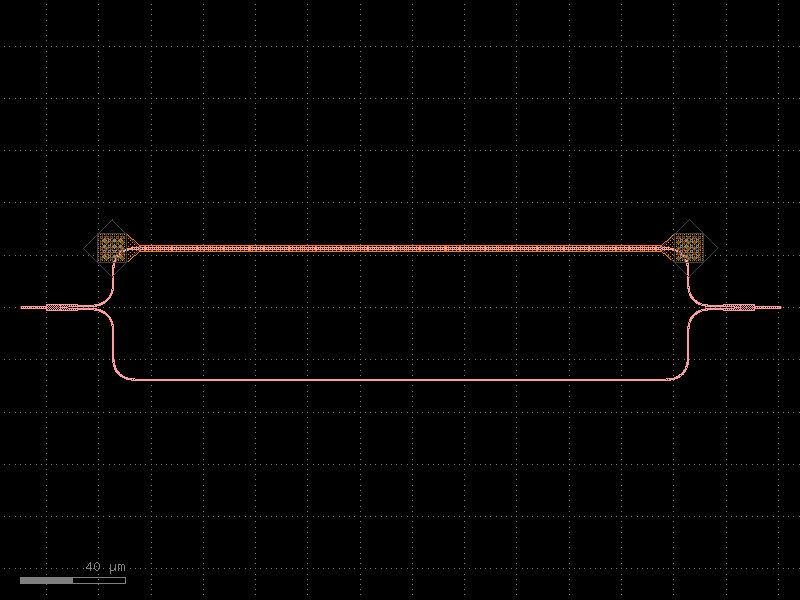
- gdsfactory.components.pcms.cutback_bend90(component='bend_euler', straight='straight', straight_length=5.0, rows=6, cols=6, spacing=5, **kwargs)[source]#
Returns bend90 cutback.
- Parameters:
component (ComponentSpec) – bend spec.
straight (ComponentSpec) – straight spec.
straight_length (float) – in um.
rows (int) – number of rows.
cols (int) – number of cols.
spacing (int) – in um.
kwargs (Any) – cross_section settings.
- Return type:
   _
|_| |
import gdsfactory as gf

gf.gpdk.PDK.activate()

c = gf.components.cutback_bend90(component='bend_euler', straight='straight', straight_length=5, rows=6, cols=6, spacing=5).copy()
c.draw_ports()
c.plot()
(Source code, png, hires.png, pdf)
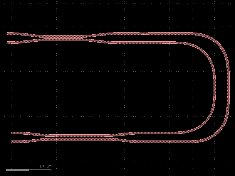
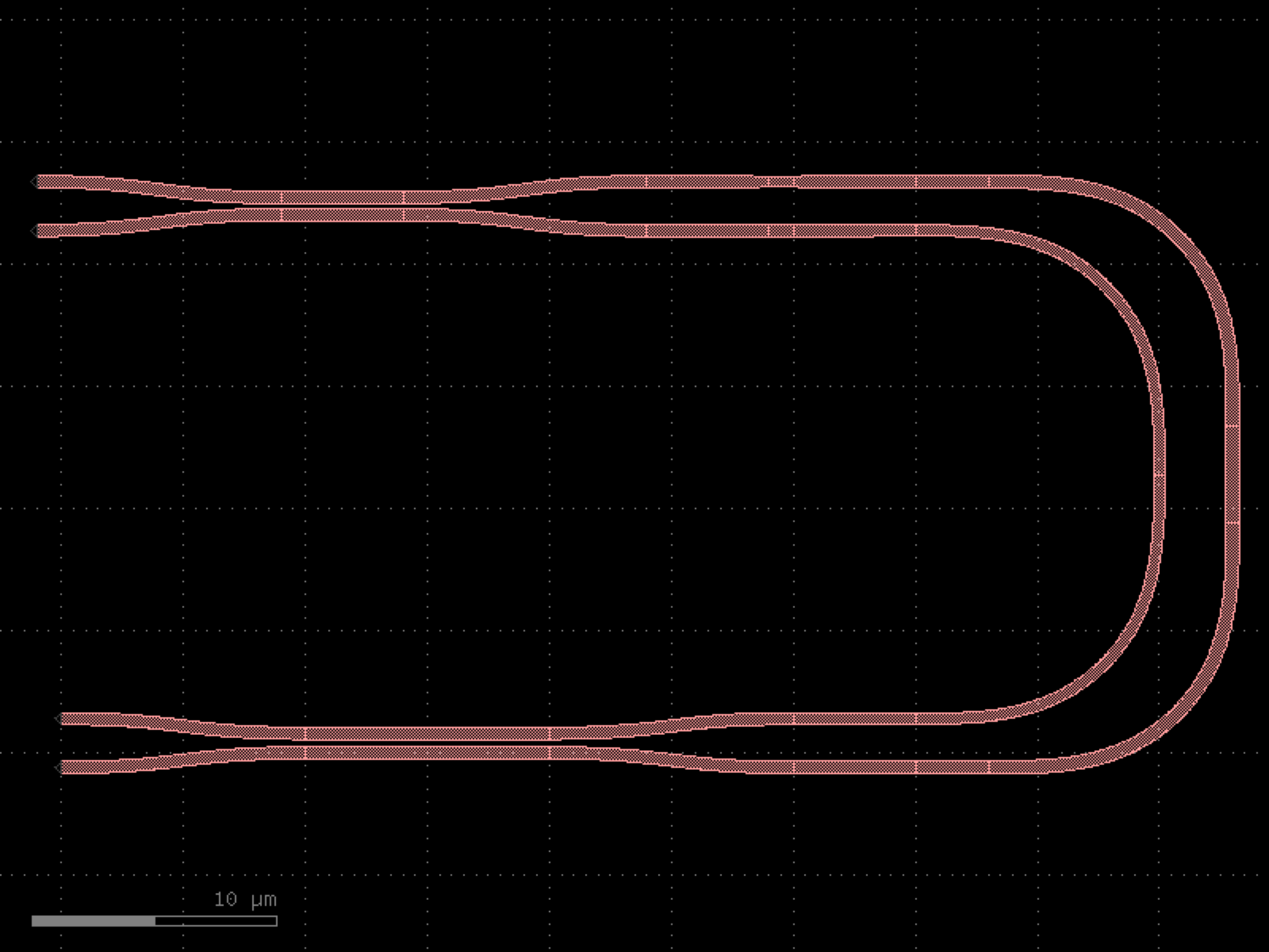

- gdsfactory.components.pcms.cutback_bend90circular(*, component='bend_circular', straight='straight', straight_length=5.0, rows=6, cols=6, spacing=5, **kwargs)#
Returns bend90 cutback.
- Parameters:
component (ComponentSpec) – bend spec.
straight (ComponentSpec) – straight spec.
straight_length (float) – in um.
rows (int) – number of rows.
cols (int) – number of cols.
spacing (int) – in um.
kwargs (Any) – cross_section settings.
- Return type:
   _
|_| |
import gdsfactory as gf

gf.gpdk.PDK.activate()

c = gf.components.cutback_bend90circular(component='bend_circular', straight='straight', straight_length=5, rows=6, cols=6, spacing=5).copy()
c.draw_ports()
c.plot()
(Source code, png, hires.png, pdf)
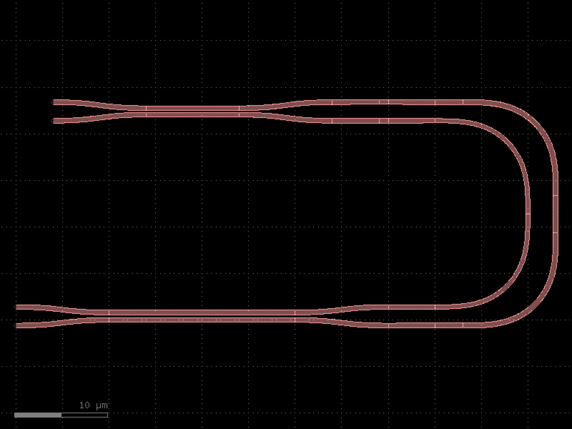
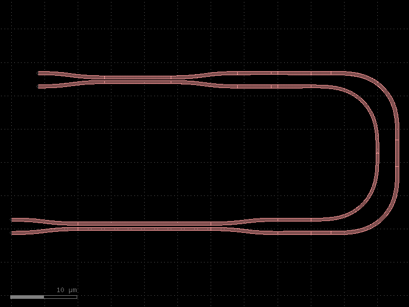
- gdsfactory.components.pcms.cutback_component(component='taper_0p5_to_3_l36', cols=4, rows=5, port1='o1', port2='o2', bend180='bend_euler180', mirror=False, mirror1=False, mirror2=False, straight_length=None, straight_length_pair=None, straight='straight', cross_section='strip', radius=None, **kwargs)[source]#
Returns a daisy chain of components for measuring their loss.
Works only for components with 2 ports (input, output).
- Parameters:
component (ComponentSpec) – for cutback.
cols (int) – number of columns.
rows (int) – number of rows.
port1 (str) – name of first optical port.
port2 (str) – name of second optical port.
bend180 (ComponentSpec) – ubend.
mirror (bool) – Flips component. Useful when ‘o2’ is the port that you want to route to.
mirror1 (bool) – mirrors first component.
mirror2 (bool) – mirrors second component.
straight_length (float | None) – length of the straight section between cutbacks.
straight_length_pair (float | None) – length of the straight section between each component pair.
cross_section (CrossSectionSpec) – specification (CrossSection, string or dict).
straight (ComponentSpec) – straight spec.
radius (float | None) – radius for the bends. Defaults to cross_section radius.
kwargs (Any) – component settings.
- Return type:
import gdsfactory as gf

gf.gpdk.PDK.activate()

c = gf.components.cutback_component(component='taper_0p5_to_3_l36', cols=4, rows=5, port1='o1', port2='o2', bend180='bend_euler180', mirror=False, mirror1=False, mirror2=False, straight='straight', cross_section='strip').copy()
c.draw_ports()
c.plot()
(Source code, png, hires.png, pdf)
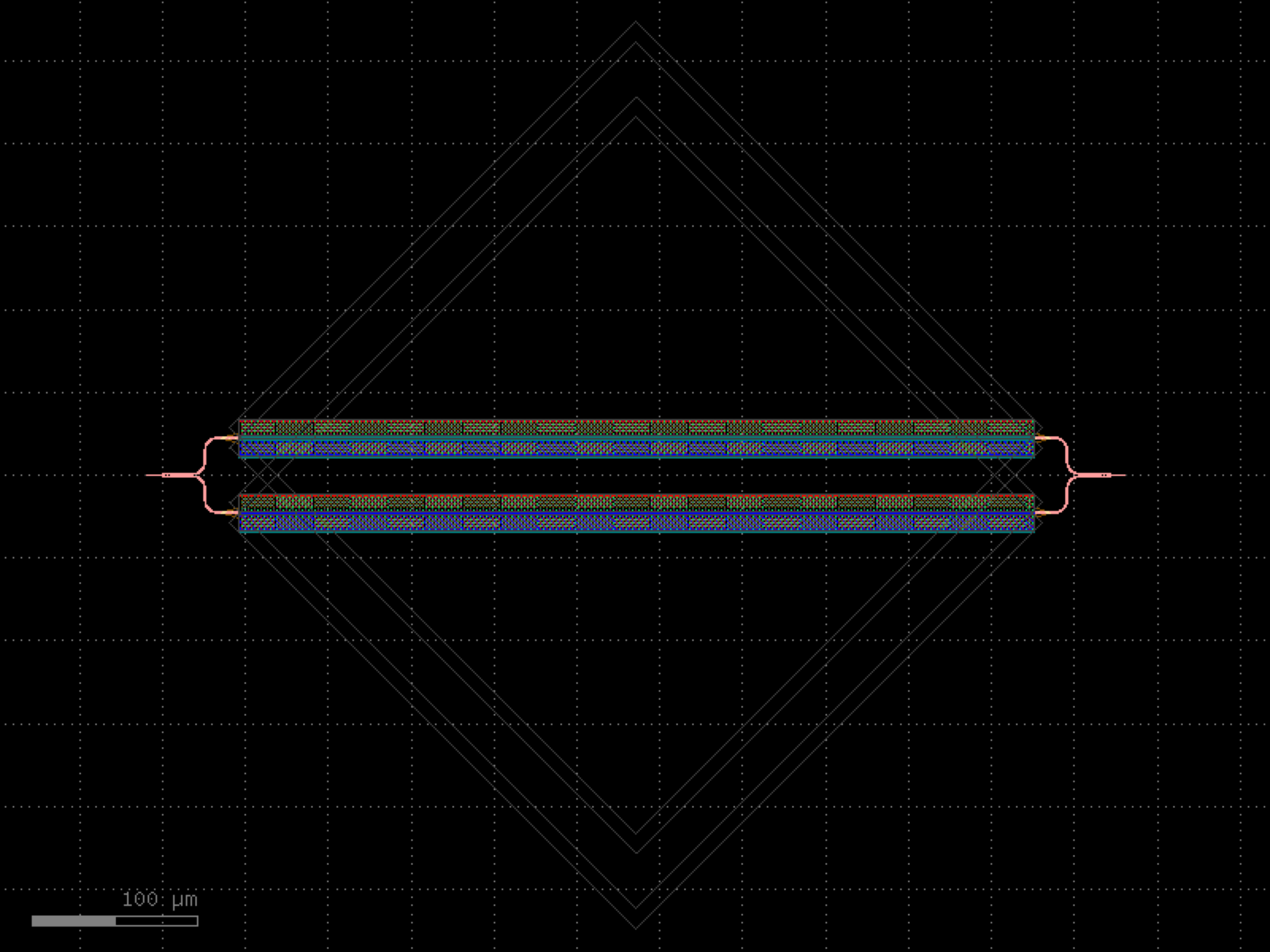
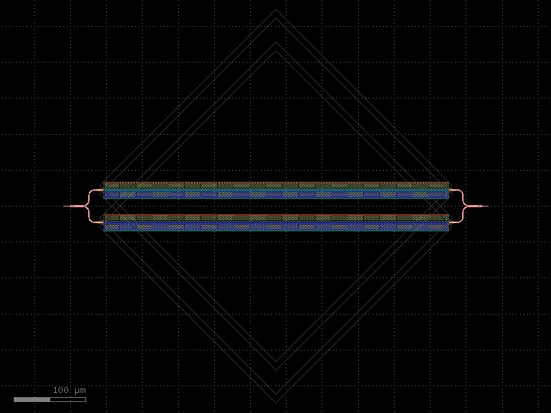
- gdsfactory.components.pcms.cutback_component_mirror(component='taper_0p5_to_3_l36', cols=4, rows=5, port1='o1', port2='o2', bend180='bend_euler180', *, mirror=True, mirror1=False, mirror2=False, straight_length=None, straight_length_pair=None, straight='straight', cross_section='strip', radius=None, **kwargs)#
Returns a daisy chain of components for measuring their loss.
Works only for components with 2 ports (input, output).
- Parameters:
component (ComponentSpec) – for cutback.
cols (int) – number of columns.
rows (int) – number of rows.
port1 (str) – name of first optical port.
port2 (str) – name of second optical port.
bend180 (ComponentSpec) – ubend.
mirror (bool) – Flips component. Useful when ‘o2’ is the port that you want to route to.
mirror1 (bool) – mirrors first component.
mirror2 (bool) – mirrors second component.
straight_length (float | None) – length of the straight section between cutbacks.
straight_length_pair (float | None) – length of the straight section between each component pair.
cross_section (CrossSectionSpec) – specification (CrossSection, string or dict).
straight (ComponentSpec) – straight spec.
radius (float | None) – radius for the bends. Defaults to cross_section radius.
kwargs (Any) – component settings.
- Return type:
import gdsfactory as gf

gf.gpdk.PDK.activate()

c = gf.components.cutback_component_mirror(component='taper_0p5_to_3_l36', cols=4, rows=5, port1='o1', port2='o2', bend180='bend_euler180', mirror=True, mirror1=False, mirror2=False, straight='straight', cross_section='strip').copy()
c.draw_ports()
c.plot()
(Source code, png, hires.png, pdf)
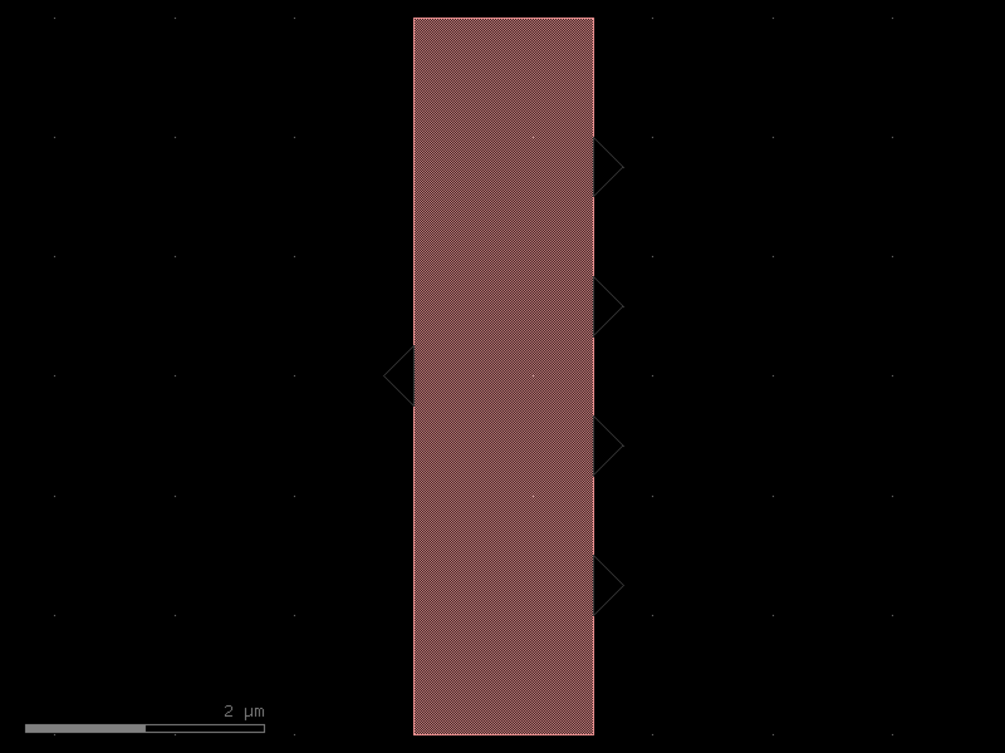
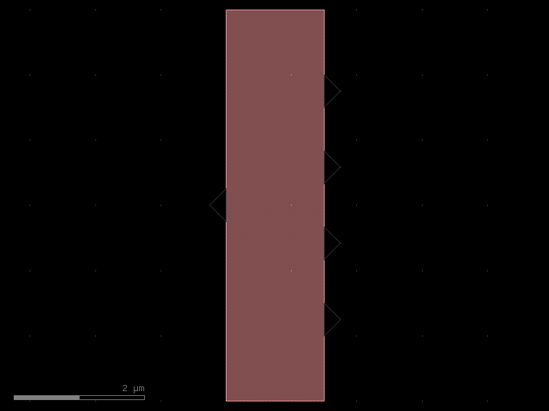
- gdsfactory.components.pcms.cutback_splitter(component='mmi1x2', cols=4, rows=5, port1='o1', port2='o2', port3='o3', bend180='bend_euler180', mirror=False, straight='straight', straight_length=None, cross_section='strip', **kwargs)[source]#
Returns a daisy chain of splitters for measuring their loss.
- Parameters:
component (ComponentSpec) – for cutback.
cols (int) – number of columns.
rows (int) – number of rows.
port1 (str) – name of first optical port.
port2 (str) – name of second optical port.
port3 (str) – name of third optical port.
bend180 (ComponentSpec) – ubend.
mirror (bool) – Flips component. Useful when ‘o2’ is the port that you want to route to.
straight (ComponentSpec) – waveguide spec to connect both sides.
straight_length (float | None) – length of the straight section between cutbacks.
cross_section (CrossSectionSpec) – specification (CrossSection, string or dict).
kwargs (Any) – cross_section settings.
- Return type:
import gdsfactory as gf

gf.gpdk.PDK.activate()

c = gf.components.cutback_splitter(component='mmi1x2', cols=4, rows=5, port1='o1', port2='o2', port3='o3', bend180='bend_euler180', mirror=False, straight='straight', cross_section='strip').copy()
c.draw_ports()
c.plot()
(Source code, png, hires.png, pdf)
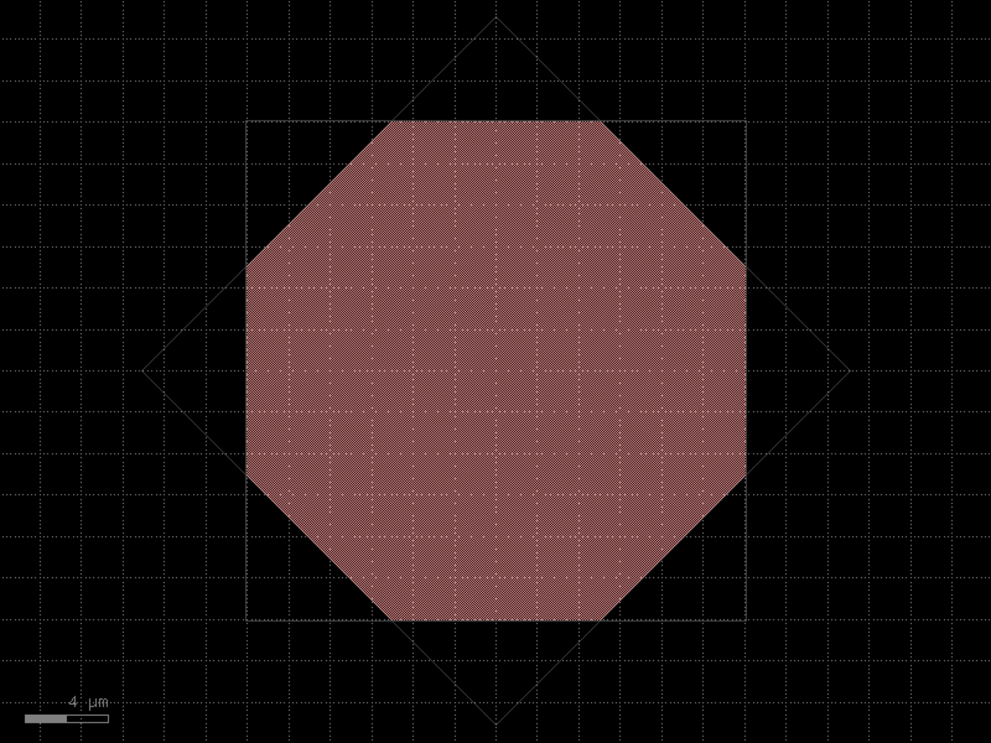

- gdsfactory.components.pcms.greek_cross(length=30, layers=('WG', 'N'), widths=(2.0, 3.0), offsets=None, via_stack='via_stack_npp_m1', layer_index=0)[source]#
Simple greek cross with via stacks at the endpoints.
Process control monitor for dopant sheet resistivity and linewidth variation.
- Parameters:
length (float) – length of cross arms.
layers (Sequence[tuple[int, int] | str | int | LayerEnum]) – list of layers.
widths (Sequence[float]) – list of widths (same order as layers).
offsets (Sequence[float] | None) – how much to extend each layer beyond the cross length negative shorter, positive longer.
via_stack (str | Callable[[...], Component] | dict[str, Any] | DKCell | partial[Component]) – via component to attach to the cross.
layer_index (int) – index of the layer to connect the via_stack to.
- Return type:
    via_stack
    <------->
    _________       length          ________
    |       |<-------------------->|        |
2x  |       |     |   ↓       |<-->|        |
    |       |======== width =======|        |
    |_______|<--> |   ↑       |<-->|________|
            offset            offset
References: - Walton, Anthony J.. “MICROELECTRONIC TEST STRUCTURES.” (1999). - W. Versnel, Analysis of the Greek cross, a Van der Pauw structure with finite
contacts, Solid-State Electronics, Volume 22, Issue 11, 1979, Pages 911-914, ISSN 0038-1101, https://doi.org/10.1016/0038-1101(79)90061-3.
S. Enderling et al., “Sheet resistance measurement of non-standard cleanroom materials using suspended Greek cross test structures,” IEEE Transactions on Semiconductor Manufacturing, vol. 19, no. 1, pp. 2-9, Feb. 2006, doi: 10.1109/TSM.2005.863248.
https://download.tek.com/document/S530_VanDerPauwSheetRstnce.pdf
import gdsfactory as gf

gf.gpdk.PDK.activate()

c = gf.components.greek_cross(length=30, layers=('WG', 'N'), widths=(2, 3), via_stack='via_stack_npp_m1', layer_index=0).copy()
c.draw_ports()
c.plot()
(Source code, png, hires.png, pdf)
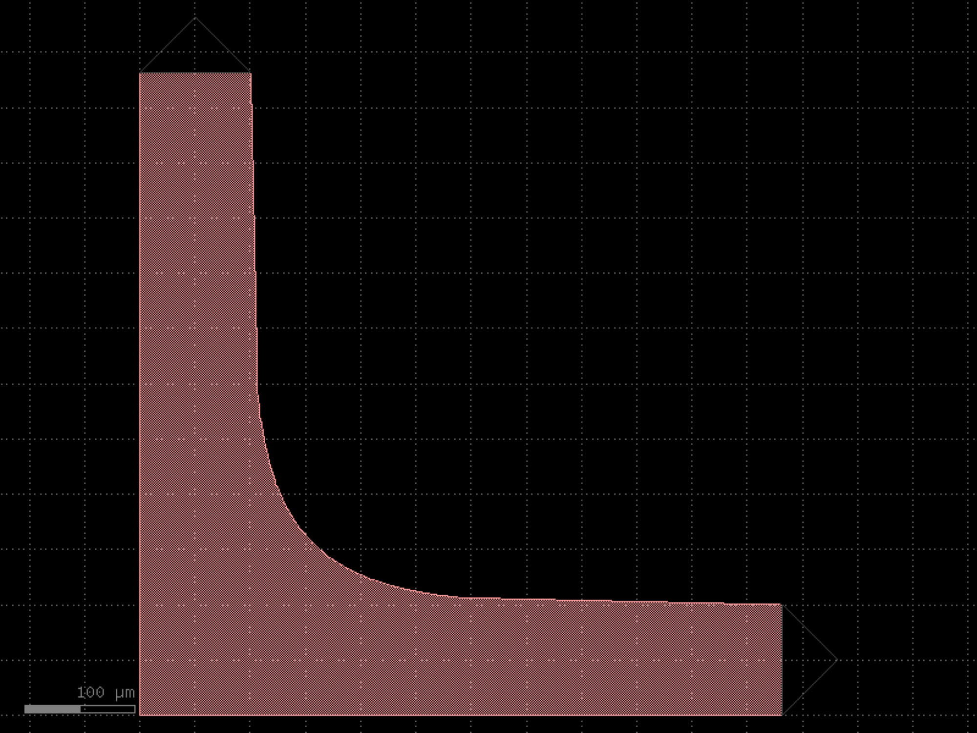

- gdsfactory.components.pcms.greek_cross_with_pads(pad='pad', pad_pitch=150.0, greek_cross_component='greek_cross', pad_via='via_stack_m1_mtop', cross_section=<function metal1>, pad_port_name='e4')[source]#
Greek cross under 4 DC pads, ready to test.
- Parameters:
pad (str | Callable[[...], Component] | dict[str, Any] | DKCell | partial[Component]) – component to use for probe pads.
pad_pitch (float) – spacing between pads.
greek_cross_component (str | Callable[[...], Component] | dict[str, Any] | DKCell | partial[Component]) – component to use for greek cross.
pad_via (str | Callable[[...], Component] | dict[str, Any] | DKCell | partial[Component]) – via to add to the pad.
cross_section (CrossSection | str | dict[str, Any] | Callable[[...], CrossSection] | SymmetricalCrossSection | DCrossSection) – cross-section for cross via to pad via wiring.
pad_port_name (str) – name of the port to connect to the greek cross.
- Return type:
import gdsfactory as gf

gf.gpdk.PDK.activate()

c = gf.components.greek_cross_with_pads(pad='pad', pad_pitch=150, greek_cross_component='greek_cross', pad_via='via_stack_m1_mtop', pad_port_name='e4').copy()
c.draw_ports()
c.plot()
(Source code, png, hires.png, pdf)
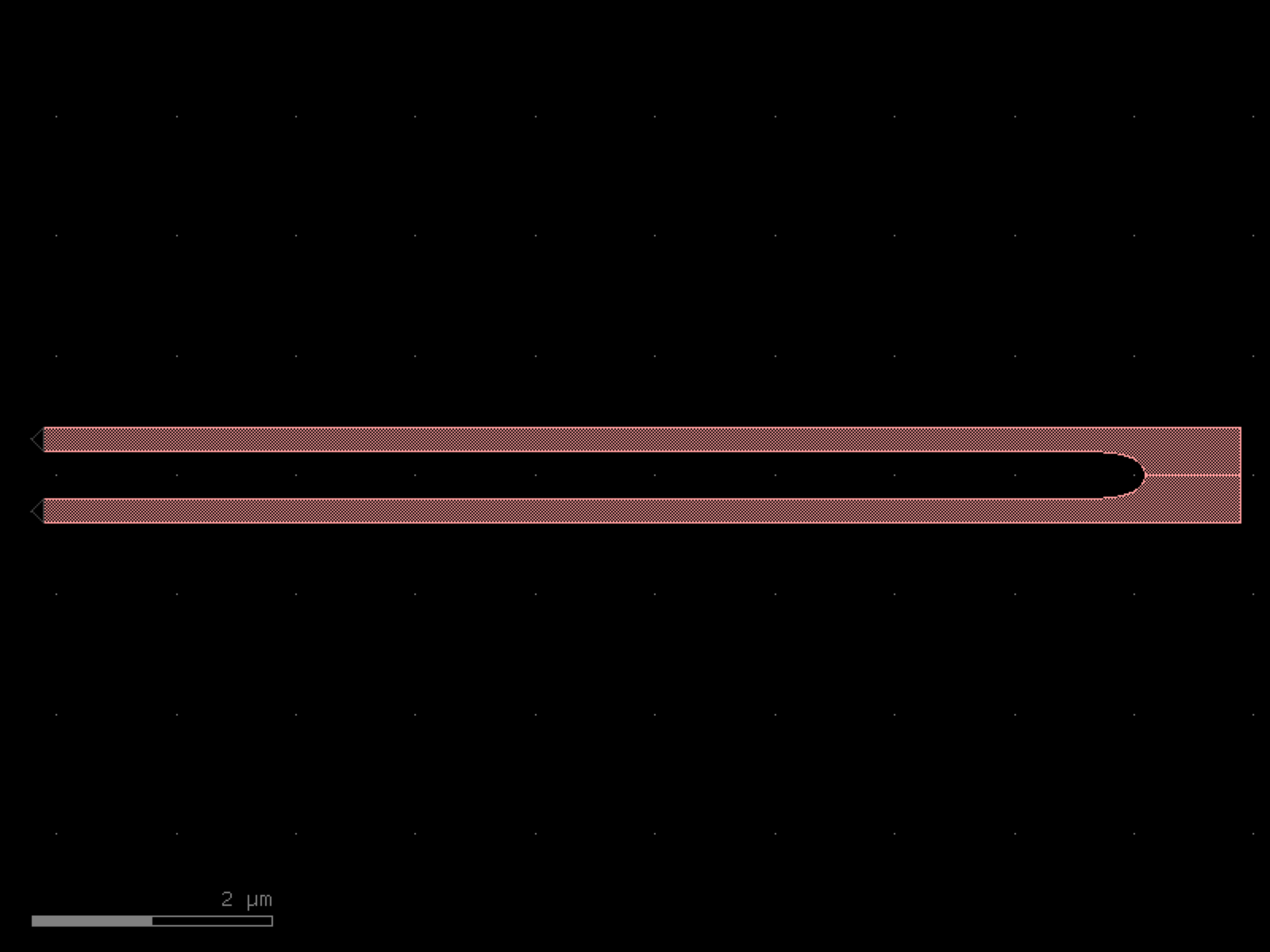
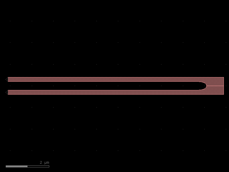
- gdsfactory.components.pcms.litho_calipers(notch_size=(2.0, 5.0), notch_spacing=2.0, num_notches=11, offset_per_notch=0.1, row_spacing=0.0, layer1='WG', layer2='SLAB150')[source]#
Vernier caliper structure to test lithography alignment.
Only the middle finger is aligned and the rest are offset. adapted from phidl
- Parameters:
notch_size (tuple[float, float]) – [xwidth, yheight].
notch_spacing (float) – in um.
num_notches (int) – number of notches.
offset_per_notch (float) – in um.
row_spacing (float) – 0
layer1 (LayerSpec) – layer.
layer2 (LayerSpec) – layer.
- Return type:
import gdsfactory as gf
gf.gpdk.PDK.activate()
c = gf.components.litho_calipers(notch_size=(2, 5), notch_spacing=2, num_notches=11, offset_per_notch=0.1, row_spacing=0, layer1='WG', layer2='SLAB150').copy()
c.draw_ports()
c.plot()
(Source code, png, hires.png, pdf)
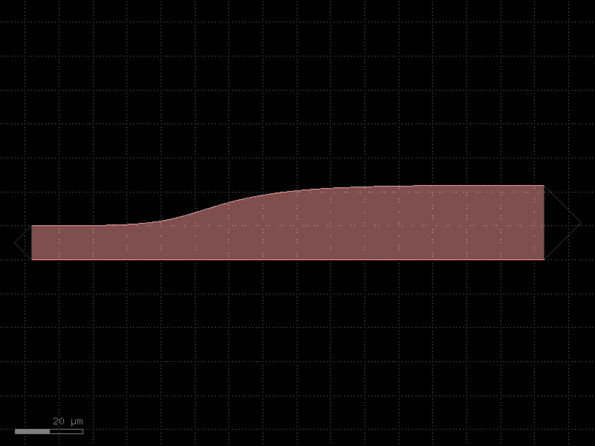

- gdsfactory.components.pcms.litho_ruler(height=2, width=0.5, spacing=2.0, scale=(3, 1, 1, 1, 1, 2, 1, 1, 1, 1), num_marks=21, layer='WG')[source]#
Ruler structure for lithographic measurement.
Includes marks of varying scales to allow for easy reading by eye.
based on phidl.geometry
- Parameters:
height (float) – Height of the ruling marks in um.
width (float) – Width of the ruling marks in um.
spacing (float) – Center-to-center spacing of the ruling marks in um.
scale (tuple[float, ...]) – Height scale pattern of marks.
num_marks (int) – Total number of marks to generate.
layer (LayerSpec) – Specific layer to put the ruler geometry on.
- Return type:
import gdsfactory as gf
gf.gpdk.PDK.activate()
c = gf.components.litho_ruler(height=2, width=0.5, spacing=2, scale=(3, 1, 1, 1, 1, 2, 1, 1, 1, 1), num_marks=21, layer='WG').copy()
c.draw_ports()
c.plot()
(Source code, png, hires.png, pdf)
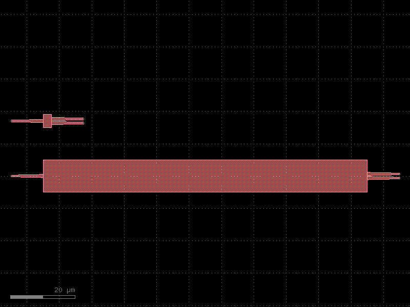

- gdsfactory.components.pcms.litho_steps(line_widths=(1.0, 2.0, 4.0, 8.0, 16.0), line_spacing=10.0, height=100.0, layer='WG')[source]#
Positive + negative tone linewidth test.
used for lithography resolution test patterning based on phidl
- Parameters:
line_widths (tuple[float, ...]) – in um.
line_spacing (float) – in um.
height (float) – in um.
layer (LayerSpec) – Specific layer to put the ruler geometry on.
- Return type:
import gdsfactory as gf
gf.gpdk.PDK.activate()
c = gf.components.litho_steps(line_widths=(1, 2, 4, 8, 16), line_spacing=10, height=100, layer='WG').copy()
c.draw_ports()
c.plot()
(Source code, png, hires.png, pdf)
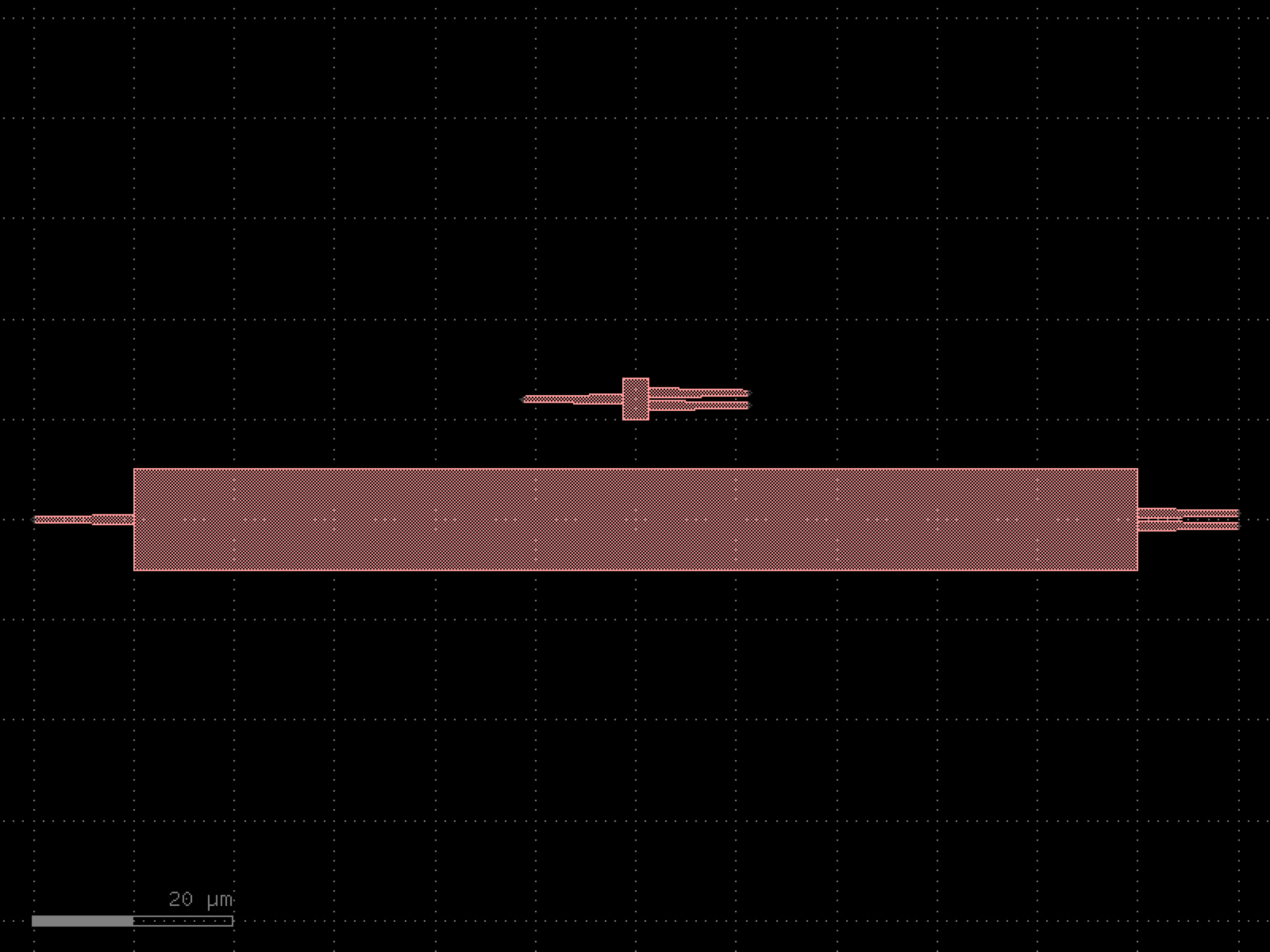

- gdsfactory.components.pcms.pixel(size=1, layer='WG')[source]#
- Parameters:
size (int)
layer (LayerSpec)
- Return type:
import gdsfactory as gf
gf.gpdk.PDK.activate()
c = gf.components.pixel(size=1, layer='WG').copy()
c.draw_ports()
c.plot()
(Source code, png, hires.png, pdf)
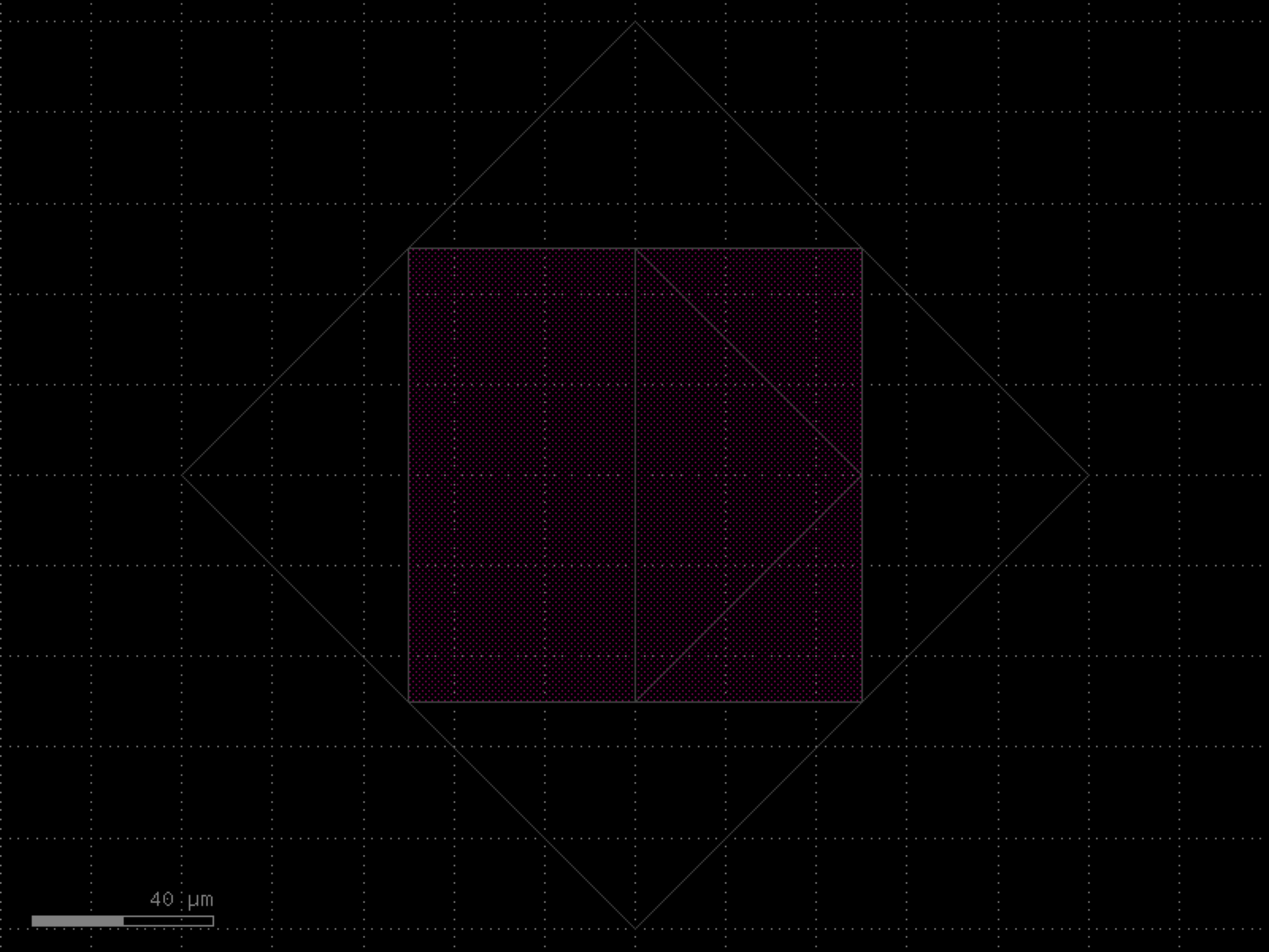
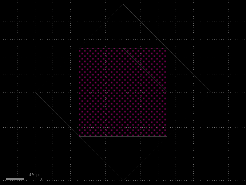
- gdsfactory.components.pcms.qrcode(data='mask01', psize=1, layer='WG')[source]#
Returns QRCode.
- Parameters:
data (str) – string to encode.
psize (int) – pixel size.
layer (LayerSpec) – layer to use.
- Return type:
import gdsfactory as gf
gf.gpdk.PDK.activate()
c = gf.components.qrcode(data='mask01', psize=1, layer='WG').copy()
c.draw_ports()
c.plot()
(Source code, png, hires.png, pdf)
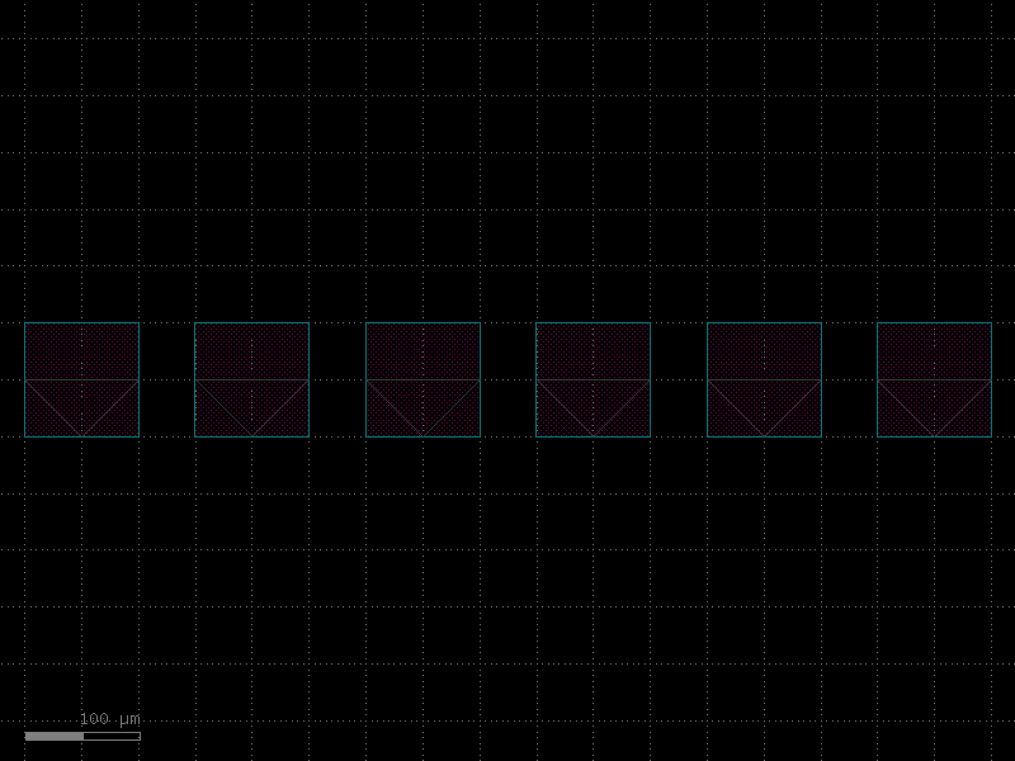

- gdsfactory.components.pcms.resistance_meander(name='net', pad_size=(50.0, 50.0), num_squares=1000, width=1.0, res_layer='MTOP', pad_layer='MTOP')[source]#
Return meander to test resistance.
based on phidl.geometry
- Parameters:
name (str) – Name of the component.
pad_size (tuple[float, float]) – Size of the two matched impedance pads (microns).
num_squares (int) – Number of squares comprising the resonator wire.
width (float) – The width of the squares (microns).
res_layer (LayerSpec) – resistance layer.
pad_layer (LayerSpec) – pad layer.
- Return type:
import gdsfactory as gf
gf.gpdk.PDK.activate()
c = gf.components.resistance_meander(name='net', pad_size=(50, 50), num_squares=1000, width=1, res_layer='MTOP', pad_layer='MTOP').copy()
c.draw_ports()
c.plot()
(Source code, png, hires.png, pdf)
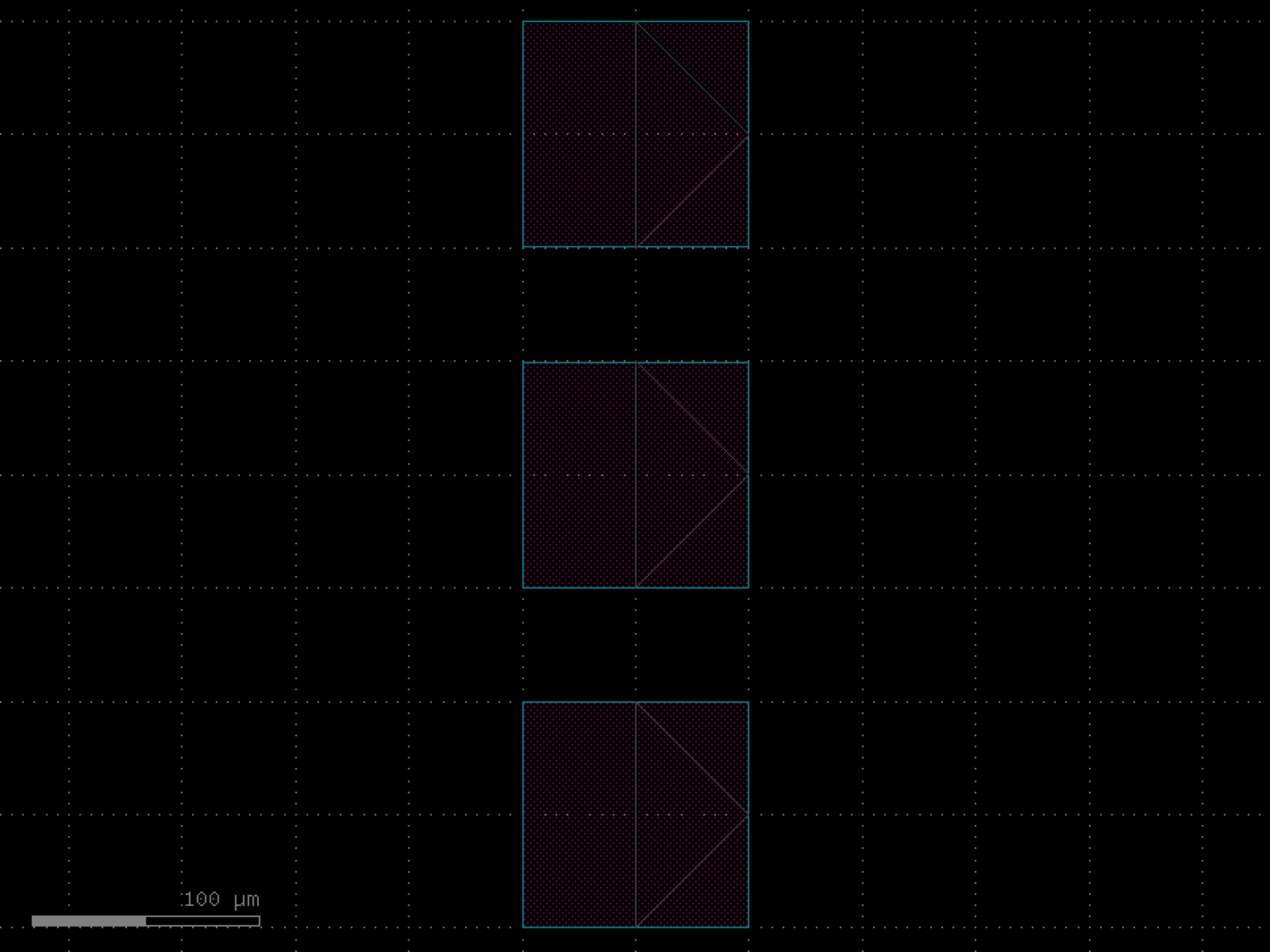
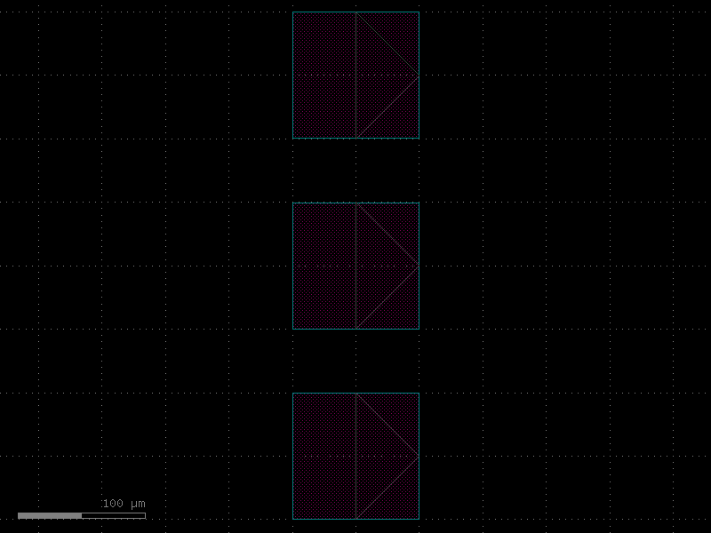
- gdsfactory.components.pcms.resistance_sheet(width=10.0, layers=('HEATER',), layer_offsets=(0, 0.2), pad='via_stack_heater_mtop', pad_size=(50.0, 50.0), pad_pitch=100.0, ohms_per_square=None, pad_port_name='e4')[source]#
Returns Sheet resistance.
keeps connectivity for pads and first layer in layers
- Parameters:
width (float) – in um.
layers (LayerSpecs) – for the middle part.
layer_offsets (Sequence[float]) – from edge, positive: over, negative: inclusion.
pad (ComponentSpec) – function to create a pad.
pad_size (tuple[float, float]) – in um.
pad_pitch (float) – in um.
ohms_per_square (float | None) – optional sheet resistance to compute info.resistance.
pad_port_name (str) – port name for the pad.
- Return type:
import gdsfactory as gf
gf.gpdk.PDK.activate()
c = gf.components.resistance_sheet(width=10, layers=('HEATER',), layer_offsets=(0, 0.2), pad='via_stack_heater_mtop', pad_size=(50, 50), pad_pitch=100, pad_port_name='e4').copy()
c.draw_ports()
c.plot()
(Source code, png, hires.png, pdf)
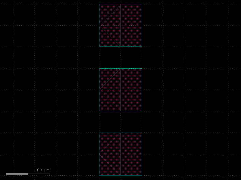
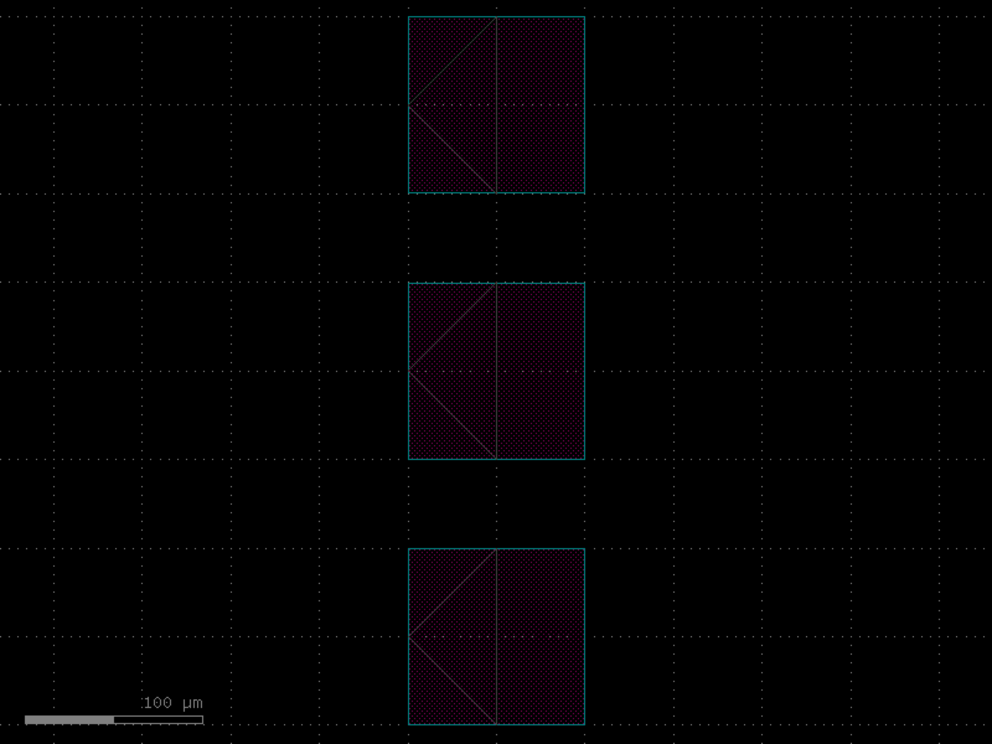

- gdsfactory.components.pcms.resolution_test_pattern(radius=50.0, n_spokes=36, width=1.0, layer='WG')[source]#
Radial Siemens star resolution test pattern.
Creates a circle of alternating filled/empty pie-shaped wedges. The pattern is useful for evaluating lithographic resolution, as the feature size decreases toward the center.
- Parameters:
radius (float) – Outer radius of the star pattern in um.
n_spokes (int) – Total number of spokes (filled + empty). Must be even.
width (float) – Target outer edge width of each spoke in um (informational; actual angular width is 360/n_spokes degrees).
layer (LayerSpec) – Layer specification for the filled wedges.
- Return type:
import gdsfactory as gf
gf.gpdk.PDK.activate()
c = gf.components.resolution_test_pattern(radius=50, n_spokes=36, width=1, layer='WG').copy()
c.draw_ports()
c.plot()
(Source code, png, hires.png, pdf)
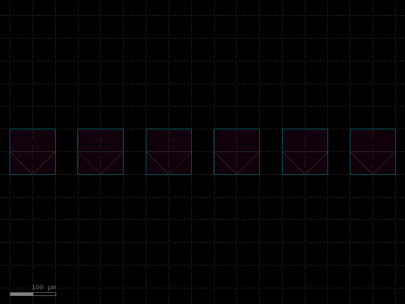
- gdsfactory.components.pcms.ruler(height_long=55, height_short=5, height_numbered=10, width=2, spacing=5.0, marks=(-100, None, -90, None, -80, None, -70, None, -60, None, -50, None, -40, None, -30, None, -20, None, -10, None, 0), layer='WG', bbox_layers=None, bbox_offset=3.0, long_marks=(-50, 0), text_size=3.5)[source]#
Ruler structure for lithographic measurement.
Includes marks of varying scales to allow for easy reading by eye.
- Parameters:
height_long (float) – Height of the long ruling marks in um.
height_short (float) – Height of the short ruling marks in um.
height_numbered (float) – Height of the numbered ruling marks in um.
width (float) – Width of the ruling marks in um.
spacing (float) – Center-to-center spacing of the ruling marks in um.
marks (tuple[float | None, ...]) – Height scale pattern of marks.
layer (LayerSpec) – Specific layer to put the ruler geometry on.
bbox_layers (tuple[LayerSpec, ...] | None) – Layers to include in the bounding box.
bbox_offset (float) – Offsets for each bounding box layer.
cross_section – Cross-section spec for the ruler. Overrides layer if provided.
long_marks (tuple[float, ...]) – Marks that are long.
text_size (float) – Size of the text in um.
- Return type:
import gdsfactory as gf
gf.gpdk.PDK.activate()
c = gf.components.ruler(height_long=55, height_short=5, height_numbered=10, width=2, spacing=5, marks=(-100, None, -90, None, -80, None, -70, None, -60, None, -50, None, -40, None, -30, None, -20, None, -10, None, 0), layer='WG', bbox_offset=3, long_marks=(-50, 0), text_size=3.5).copy()
c.draw_ports()
c.plot()
(Source code, png, hires.png, pdf)
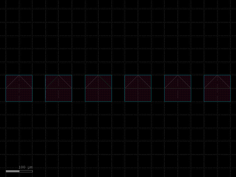
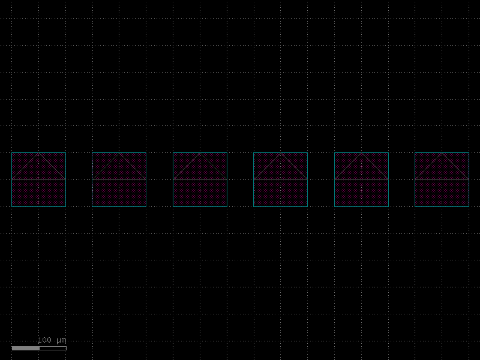

- gdsfactory.components.pcms.staircase(component='bend_euler', straight='straight', length_v=5.0, length_h=5.0, rows=4, **kwargs)[source]#
Returns staircase.
import gdsfactory as gf
gf.gpdk.PDK.activate()
c = gf.components.staircase(component='bend_euler', straight='straight', length_v=5, length_h=5, rows=4).copy()
c.draw_ports()
c.plot()
(Source code, png, hires.png, pdf)
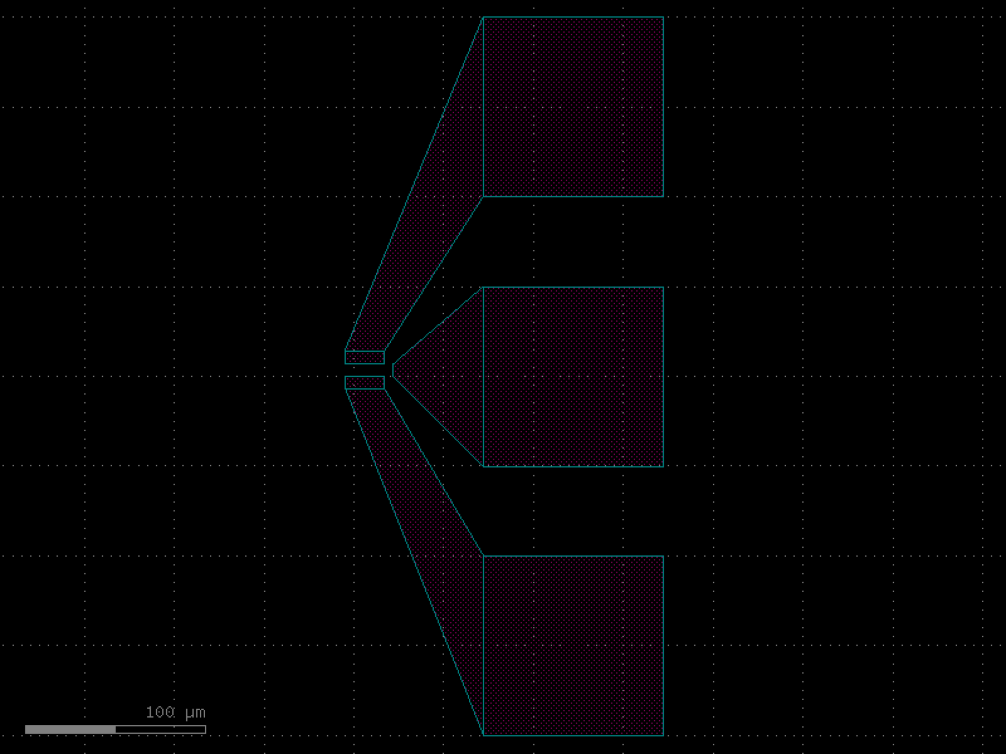

- gdsfactory.components.pcms.vernier_scale(n_divisions=10, pitch_main=10.0, pitch_vernier=9.8, mark_width=1.0, mark_height_main=20.0, mark_height_vernier=15.0, layer_main='WG', layer_vernier=(2, 0))[source]#
Vernier scale for overlay measurement.
Creates two rows of rectangular marks: a main scale and a vernier scale. The slight pitch difference between the two scales allows sub-pitch overlay measurement. The zero marks of both scales are centered at the origin.
- Parameters:
n_divisions (int) – Number of marks on each side of the center mark (total marks per scale = 2 * n_divisions + 1).
pitch_main (float) – Center-to-center spacing of main scale marks in um.
pitch_vernier (float) – Center-to-center spacing of vernier scale marks in um.
mark_width (float) – Width of each rectangular mark in um.
mark_height_main (float) – Height of each main scale mark in um.
mark_height_vernier (float) – Height of each vernier scale mark in um.
layer_main (LayerSpec) – Layer specification for the main scale marks.
layer_vernier (LayerSpec) – Layer specification for the vernier scale marks.
- Return type:
import gdsfactory as gf
gf.gpdk.PDK.activate()
c = gf.components.vernier_scale(n_divisions=10, pitch_main=10, pitch_vernier=9.8, mark_width=1, mark_height_main=20, mark_height_vernier=15, layer_main='WG', layer_vernier=(2, 0)).copy()
c.draw_ports()
c.plot()
(Source code, png, hires.png, pdf)
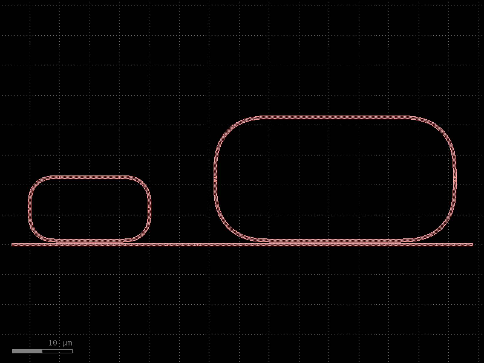
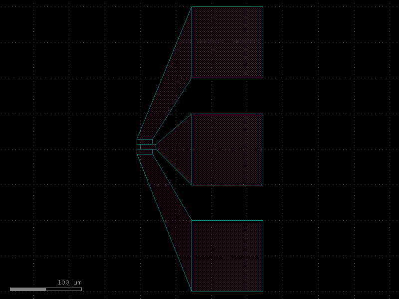
- gdsfactory.components.pcms.verniers(widths=(0.1, 0.2, 0.3, 0.4, 0.5), gap=0.1, xsize=100.0, layer_label='TEXT', straight='straight', cross_section='strip_no_ports', **kwargs)[source]#
Returns a component with verniers.
- Parameters:
widths (Sequence[float]) – list of widths.
gap (float) – gap between verniers.
xsize (float) – size of the component.
layer_label (LayerSpec) – layer for the labels.
straight (ComponentSpec) – straight function.
cross_section (CrossSectionSpec) – cross_section spec.
kwargs (Any) – straight settings.
- Return type:
import gdsfactory as gf
gf.gpdk.PDK.activate()
c = gf.components.verniers(widths=(0.1, 0.2, 0.3, 0.4, 0.5), gap=0.1, xsize=100, layer_label='TEXT', straight='straight', cross_section='strip_no_ports').copy()
c.draw_ports()
c.plot()
(Source code, png, hires.png, pdf)
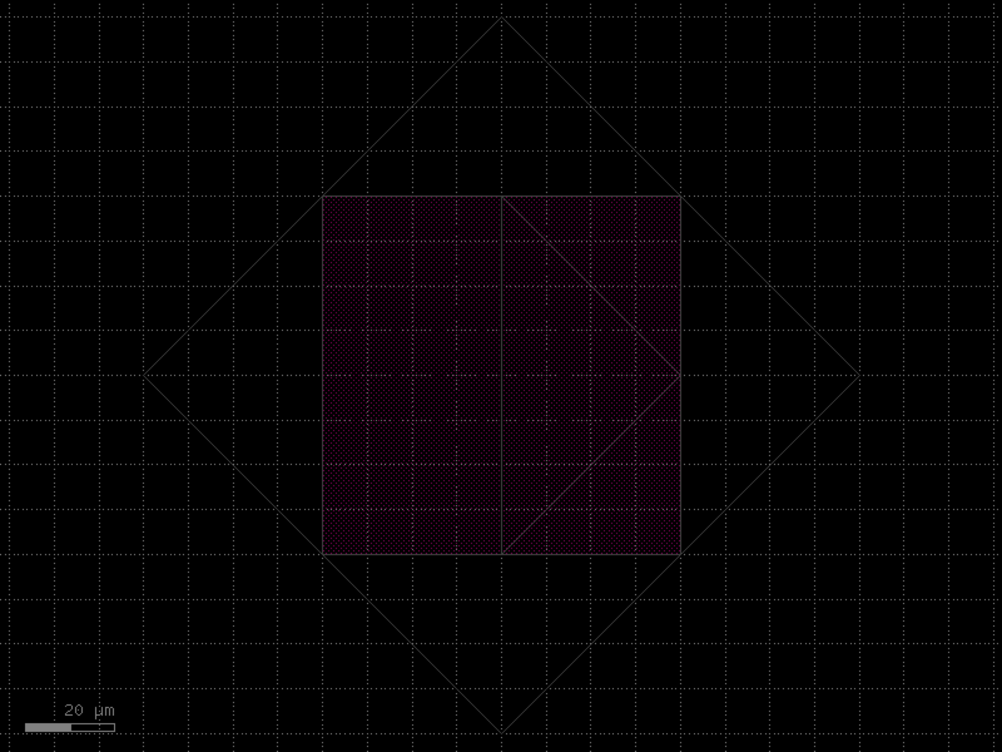
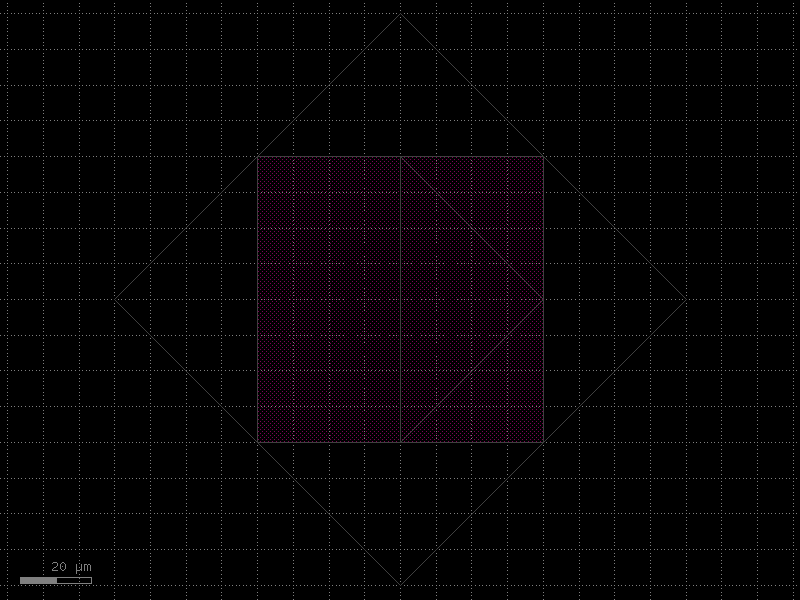
- gdsfactory.components.pcms.version_stamp(labels=('demo_label',), with_qr_code=False, layer='WG', pixel_size=1, version=None, text_size=10)[source]#
Component with module version and date.
- Parameters:
labels (tuple[str, ...]) – Iterable of labels.
with_qr_code (bool) – Whether to add a QR code with the date.
layer (LayerSpec) – Layer to use.
pixel_size (int) – Pixel size.
version (str | None) – Version string.
text_size (int) – Text size.
- Return type:
import gdsfactory as gf
gf.gpdk.PDK.activate()
c = gf.components.version_stamp(labels=('demo_label',), with_qr_code=False, layer='WG', pixel_size=1, text_size=10).copy()
c.draw_ports()
c.plot()
(Source code, png, hires.png, pdf)
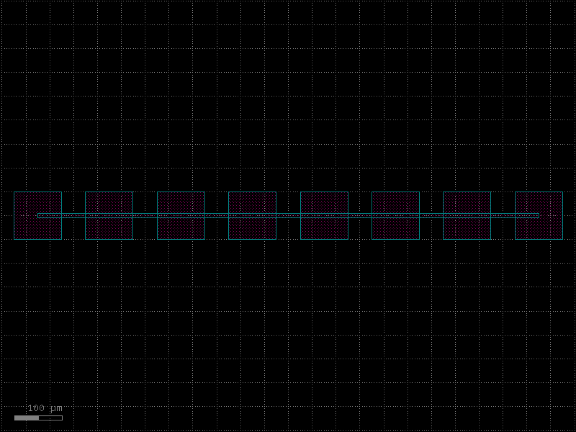
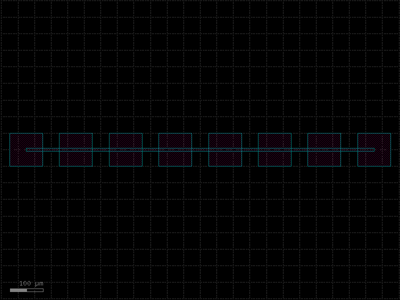
quantum#
- gdsfactory.components.quantum.coupler_capacitive(pad_width=20.0, pad_height=50.0, gap=2.0, feed_width=10.0, feed_length=30.0, layer_metal=(1, 0), port_type='electrical')[source]#
Creates a capacitive coupler for quantum circuits.
A capacitive coupler consists of two metal pads separated by a small gap, providing capacitive coupling between circuit elements like qubits and resonators.
______ ______ _______ | | | | _______ | | | | | || | | feed1 | | pad1 | ====gap==== | pad2 || feed2 | | | | | | || | |_______| | | | ||_______| |______| |______|
- Parameters:
pad_width (float) – Width of each coupling pad in μm.
pad_height (float) – Height of each coupling pad in μm.
gap (float) – Gap between the coupling pads in μm.
feed_width (float) – Width of the feed lines in μm.
feed_length (float) – Length of the feed lines in μm.
layer_metal (LayerSpec) – Layer for the metal structures.
port_type (str) – Type of port to add to the component.
- Returns:
A gdsfactory component with the capacitive coupler geometry.
- Return type:
import gdsfactory as gf
gf.gpdk.PDK.activate()
c = gf.components.coupler_capacitive(pad_width=20, pad_height=50, gap=2, feed_width=10, feed_length=30, layer_metal=(1, 0), port_type='electrical').copy()
c.draw_ports()
c.plot()
(Source code, png, hires.png, pdf)

- gdsfactory.components.quantum.coupler_interdigital(fingers=6, finger_length=30.0, finger_width=2.0, finger_gap_vertical=2.0, finger_gap_horizontal=3.0, feed_width=10.0, feed_length=30.0, layer_metal=(1, 0), port_type='electrical')[source]#
Creates an interdigital capacitive coupler.
Each side includes a base column (a vertical metal block) to which the fingers are attached.
The width of the base column is equal to the height of the fingers.
The finger_length parameter refers only to the length of the fingers extending from the base, and does NOT include the base column width
- Parameters:
fingers (int) – Number of fingers per side.
finger_length (float) – Length of each finger in μm (see note above).
finger_width (float) – Width of each finger in μm.
finger_gap_vertical (float) – Vertical gap between fingers in μm (g1).
finger_gap_horizontal (float) – Horizontal gap between fingers in μm (g2).
feed_width (float) – Width of the feed lines in μm.
feed_length (float) – Length of the feed lines in μm.
layer_metal (LayerSpec) – Layer for the metal structures.
port_type (str) – Type of port to add to the component.
- Returns:
A gdsfactory component with the interdigital coupler geometry.
- Return type:
┌────────┐ base columns ↓ ↓ ┌────────┐ ┌────────┐ │ │█████████████ █│ │ │ │█ g1 █│ │ │ │█ <─g2─> █████████████│ │ │ │█ █│ │ │ feed1 │█████████████ █│ feed2 │ │ │█ █│ │ │ │█ █████████████│ │ │ │█ █│ │ │ │█████████████ █│ │ └────────┘█ █└────────┘
import gdsfactory as gf
gf.gpdk.PDK.activate()
c = gf.components.coupler_interdigital(fingers=6, finger_length=30, finger_width=2, finger_gap_vertical=2, finger_gap_horizontal=3, feed_width=10, feed_length=30, layer_metal=(1, 0), port_type='electrical').copy()
c.draw_ports()
c.plot()
(Source code, png, hires.png, pdf)
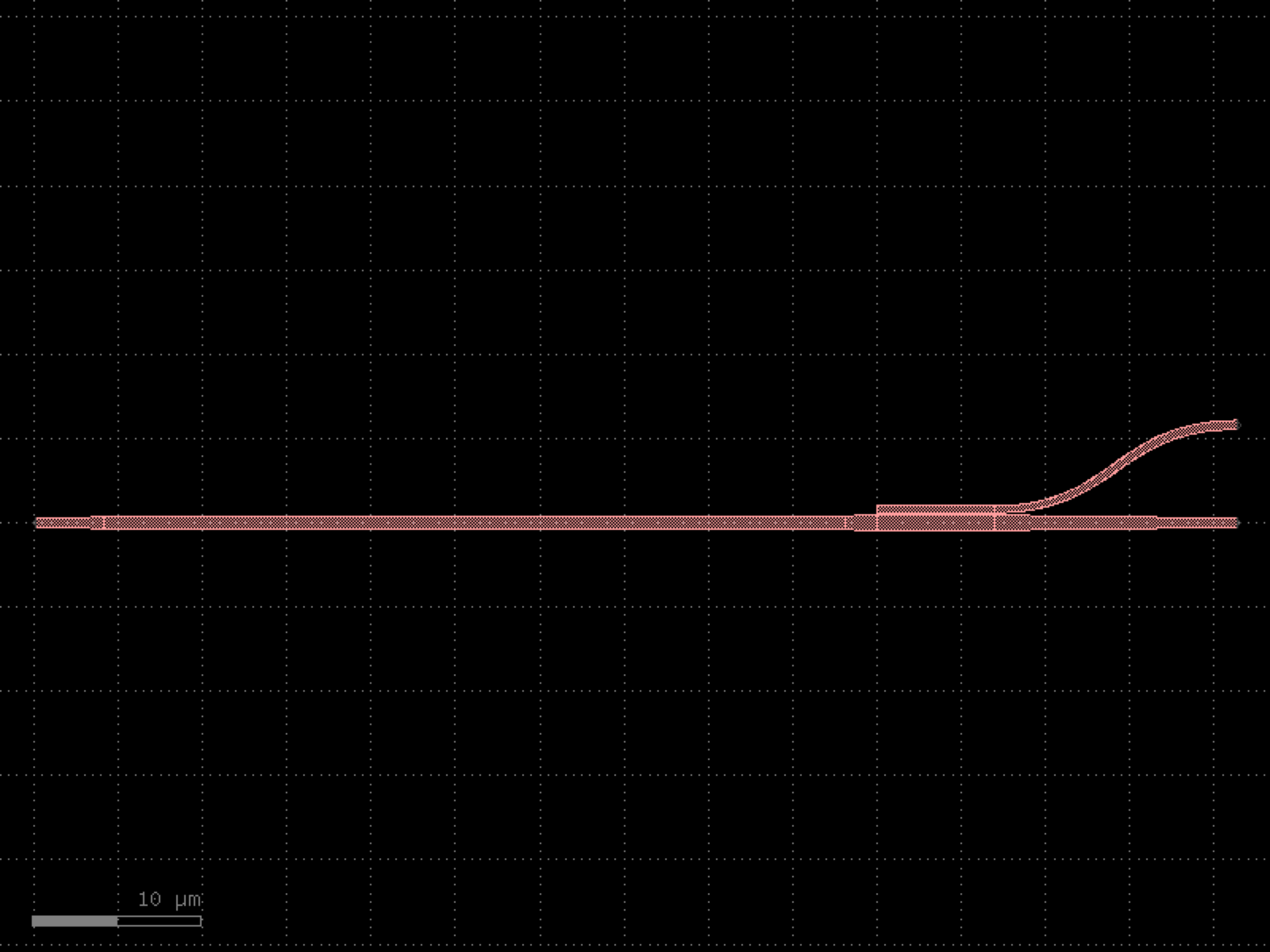

- gdsfactory.components.quantum.coupler_tunable(pad_width=30.0, pad_height=40.0, gap=3.0, tuning_pad_width=15.0, tuning_pad_height=20.0, tuning_gap=1.0, feed_width=10.0, feed_length=30.0, layer_metal=(1, 0), layer_tuning=(3, 0), port_type='electrical')[source]#
Creates a tunable capacitive coupler with voltage control.
A tunable coupler includes additional electrodes that can be voltage-biased to change the coupling strength dynamically.
- Parameters:
pad_width (float) – Width of main coupling pads in μm.
pad_height (float) – Height of main coupling pads in μm.
gap (float) – Gap between main coupling pads in μm.
tuning_pad_width (float) – Width of tuning pads in μm.
tuning_pad_height (float) – Height of tuning pads in μm.
tuning_gap (float) – Gap to tuning pads in μm.
feed_width (float) – Width of feed lines in μm.
feed_length (float) – Length of feed lines in μm.
layer_metal (LayerSpec) – Layer for main metal structures.
layer_tuning (LayerSpec) – Layer for tuning electrodes.
port_type (str) – Type of port to add to the component.
- Returns:
A gdsfactory component with the tunable coupler geometry.
- Return type:
(connected to feed) _______ | | | tpad1 | | | |_______| tuning gap ______ ______ _______ | | | | _______ | | | | | || | | feed1 | | pad1 | gap | pad2 || feed2 | | | | | | || | |_______| | | | ||_______| |______| |______| tuning gap _______ | | | tpad2 | | | |_______| (connected to feed)
import gdsfactory as gf
gf.gpdk.PDK.activate()
c = gf.components.coupler_tunable(pad_width=30, pad_height=40, gap=3, tuning_pad_width=15, tuning_pad_height=20, tuning_gap=1, feed_width=10, feed_length=30, layer_metal=(1, 0), layer_tuning=(3, 0), port_type='electrical').copy()
c.draw_ports()
c.plot()
(Source code, png, hires.png, pdf)
- gdsfactory.components.quantum.flux_qubit(loop_width=50.0, loop_height=50.0, junction_width=0.15, junction_height=0.3, alpha_junction_width=0.12, alpha_junction_height=0.25, wire_width=2.0, layer_metal=(1, 0), layer_junction=(2, 0), layer_alpha_junction=(3, 0), port_type='electrical')[source]#
Creates a flux qubit (persistent current qubit).
A flux qubit consists of a superconducting loop interrupted by three Josephson junctions. Two junctions are identical (beta junctions) while the third is smaller (alpha junction) with roughly 0.5-0.8 times the critical current.
- Parameters:
loop_width (float) – Width of the superconducting loop in μm.
loop_height (float) – Height of the superconducting loop in μm.
junction_width (float) – Width of the beta Josephson junctions in μm.
junction_height (float) – Height of the beta Josephson junctions in μm.
alpha_junction_width (float) – Width of the alpha Josephson junction in μm.
alpha_junction_height (float) – Height of the alpha Josephson junction in μm.
wire_width (float) – Width of the superconducting wires in μm.
layer_metal (LayerSpec) – Layer for the metal wires.
layer_junction (LayerSpec) – Layer for the beta Josephson junctions.
layer_alpha_junction (LayerSpec) – Layer for the alpha Josephson junction.
port_type (str) – Type of port to add to the component.
- Returns:
A gdsfactory component with the flux qubit geometry.
- Return type:
import gdsfactory as gf
gf.gpdk.PDK.activate()
c = gf.components.flux_qubit(loop_width=50, loop_height=50, junction_width=0.15, junction_height=0.3, alpha_junction_width=0.12, alpha_junction_height=0.25, wire_width=2, layer_metal=(1, 0), layer_junction=(2, 0), layer_alpha_junction=(3, 0), port_type='electrical').copy()
c.draw_ports()
c.plot()
(Source code, png, hires.png, pdf)

- gdsfactory.components.quantum.flux_qubit_asymmetric(loop_width=60.0, loop_height=40.0, junction_width=0.15, junction_height=0.3, alpha_junction_width=0.12, alpha_junction_height=0.25, wire_width=2.0, asymmetry_angle=15.0, layer_metal=(1, 0), layer_junction=(2, 0), layer_alpha_junction=(3, 0), port_type='electrical')[source]#
Creates an asymmetric flux qubit for reduced flux noise sensitivity.
An asymmetric flux qubit has a loop geometry that is not perfectly symmetric, which can help reduce sensitivity to flux noise while maintaining controllability.
- Parameters:
loop_width (float) – Width of the superconducting loop in μm.
loop_height (float) – Height of the superconducting loop in μm.
junction_width (float) – Width of the beta Josephson junctions in μm.
junction_height (float) – Height of the beta Josephson junctions in μm.
alpha_junction_width (float) – Width of the alpha Josephson junction in μm.
alpha_junction_height (float) – Height of the alpha Josephson junction in μm.
wire_width (float) – Width of the superconducting wires in μm.
asymmetry_angle (float) – Angle of asymmetry in degrees.
layer_metal (LayerSpec) – Layer for the metal wires.
layer_junction (LayerSpec) – Layer for the beta Josephson junctions.
layer_alpha_junction (LayerSpec) – Layer for the alpha Josephson junction.
port_type (str) – Type of port to add to the component.
- Returns:
A gdsfactory component with the asymmetric flux qubit geometry.
- Return type:
import gdsfactory as gf
gf.gpdk.PDK.activate()
c = gf.components.flux_qubit_asymmetric(loop_width=60, loop_height=40, junction_width=0.15, junction_height=0.3, alpha_junction_width=0.12, alpha_junction_height=0.25, wire_width=2, asymmetry_angle=15, layer_metal=(1, 0), layer_junction=(2, 0), layer_alpha_junction=(3, 0), port_type='electrical').copy()
c.draw_ports()
c.plot()
(Source code, png, hires.png, pdf)
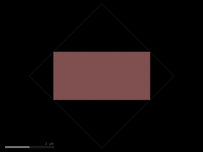
- gdsfactory.components.quantum.resonator_cpw(length=1000.0, width=10.0, gap=6.0, meander_pitch=50.0, meander_width=200.0, coupling_gap=5.0, coupling_length=100.0, layer_metal=(1, 0), layer_gap=(2, 0), port_type='electrical')[source]#
Creates a coplanar waveguide (CPW) resonator.
A CPW resonator consists of a meandered coplanar waveguide with coupling gaps for capacitive coupling to feedlines or qubits.
- Parameters:
length (float) – Total length of the resonator in μm.
width (float) – Width of the center conductor in μm.
gap (float) – Gap width on each side of the center conductor in μm.
meander_pitch (float) – Pitch between meander segments in μm.
meander_width (float) – Width of each meander section in μm.
coupling_gap (float) – Gap for capacitive coupling in μm.
coupling_length (float) – Length of the coupling region in μm.
layer_metal (LayerSpec) – Layer for the metal conductor.
layer_gap (LayerSpec) – Layer for the gaps (ground plane).
port_type (str) – Type of port to add to the component.
- Returns:
A gdsfactory component with the CPW resonator geometry.
- Return type:
import gdsfactory as gf
gf.gpdk.PDK.activate()
c = gf.components.resonator_cpw(length=1000, width=10, gap=6, meander_pitch=50, meander_width=200, coupling_gap=5, coupling_length=100, layer_metal=(1, 0), layer_gap=(2, 0), port_type='electrical').copy()
c.draw_ports()
c.plot()
(Source code, png, hires.png, pdf)
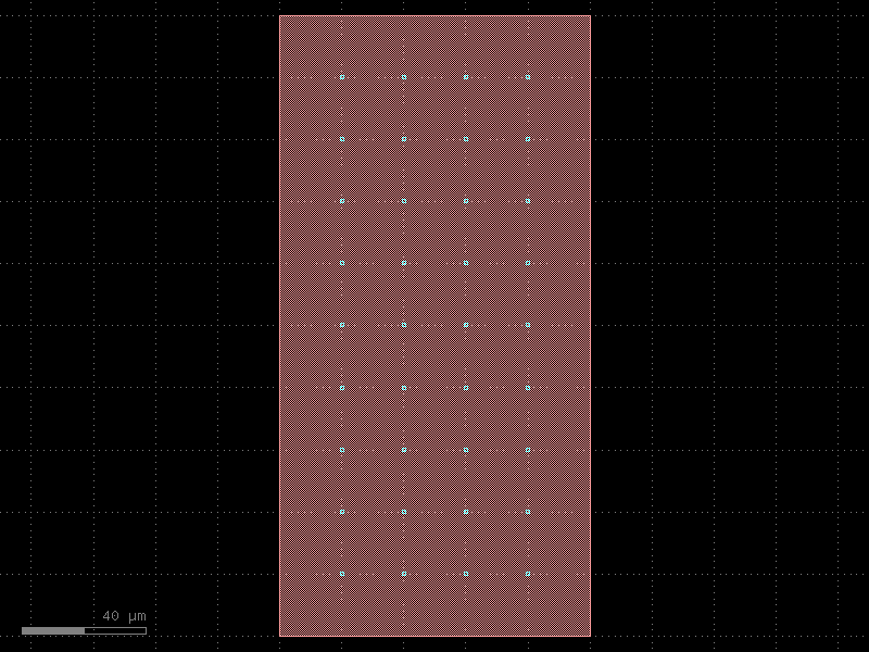
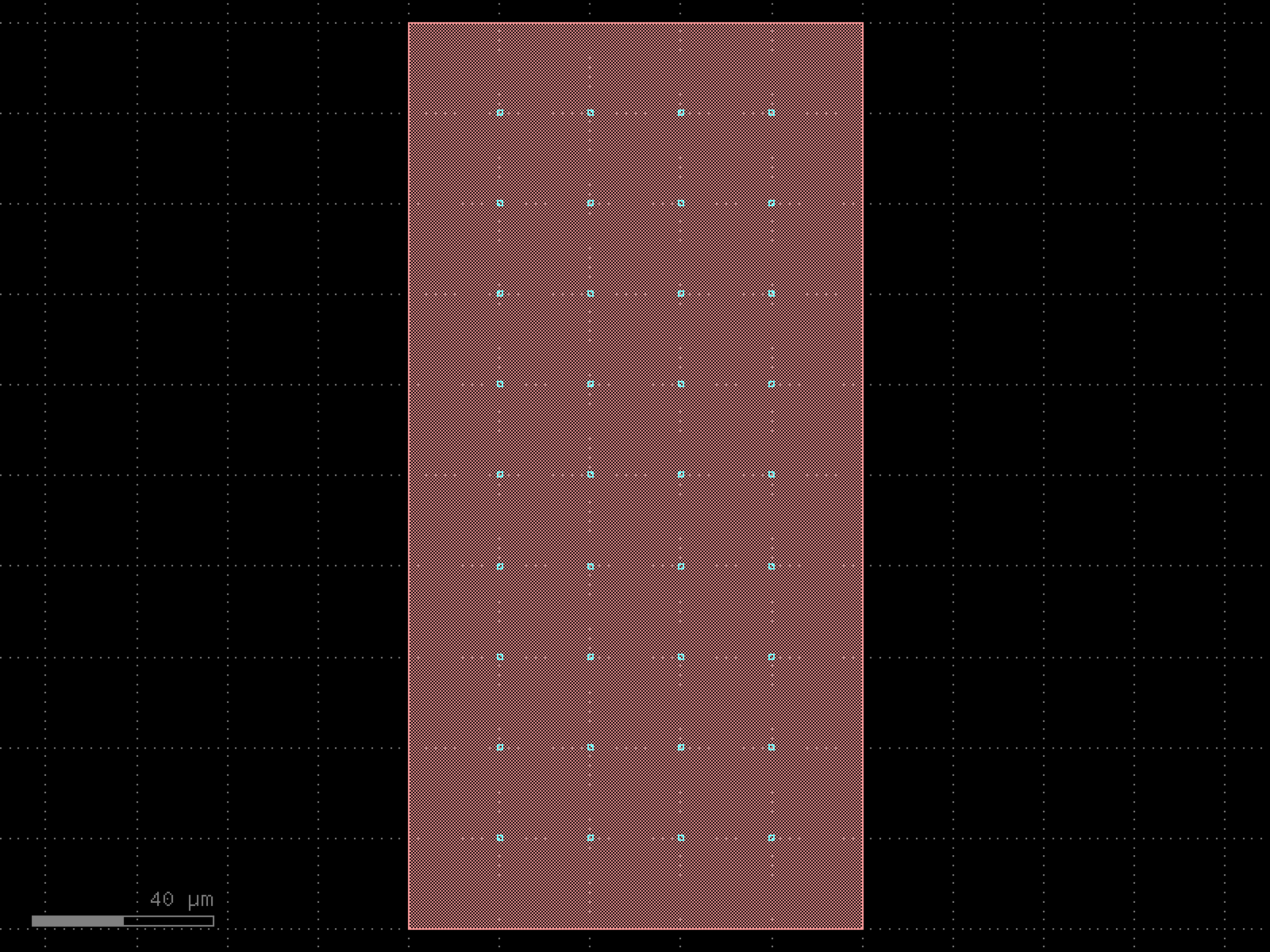

- gdsfactory.components.quantum.resonator_lumped(capacitor_fingers=4, capacitor_finger_length=20.0, capacitor_finger_gap=2.0, capacitor_thickness=5.0, inductor_width=2.0, inductor_turns=3, inductor_radius=20.0, coupling_gap=5.0, layer_metal=(1, 0), port_type='electrical')[source]#
Creates a lumped element resonator with interdigital capacitor and spiral inductor.
A lumped resonator consists of a capacitive element (interdigital capacitor) and an inductive element (spiral inductor) forming an LC circuit.
- Parameters:
capacitor_fingers (int) – Number of fingers in the interdigital capacitor.
capacitor_finger_length (float) – Length of each capacitor finger in μm.
capacitor_finger_gap (float) – Gap between capacitor fingers in μm.
capacitor_thickness (float) – Thickness of capacitor fingers in μm.
inductor_width (float) – Width of the inductor wire in μm.
inductor_turns (int) – Number of turns in the spiral inductor.
inductor_radius (float) – Radius of the spiral inductor in μm.
coupling_gap (float) – Gap for capacitive coupling in μm.
layer_metal (LayerSpec) – Layer for the metal structures.
port_type (str) – Type of port to add to the component.
- Returns:
A gdsfactory component with the lumped resonator geometry.
- Return type:
import gdsfactory as gf
gf.gpdk.PDK.activate()
c = gf.components.resonator_lumped(capacitor_fingers=4, capacitor_finger_length=20, capacitor_finger_gap=2, capacitor_thickness=5, inductor_width=2, inductor_turns=3, inductor_radius=20, coupling_gap=5, layer_metal=(1, 0), port_type='electrical').copy()
c.draw_ports()
c.plot()
(Source code, png, hires.png, pdf)
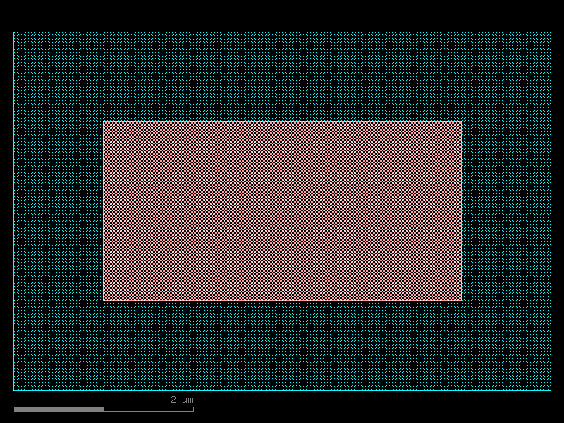
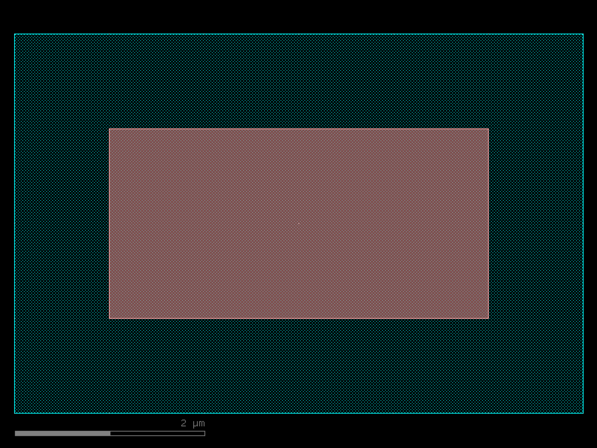

- gdsfactory.components.quantum.resonator_quarter_wave(length=2500.0, width=10.0, gap=6.0, short_stub_length=50.0, coupling_gap=5.0, coupling_length=100.0, layer_metal=(1, 0), layer_gap=(2, 0), port_type='electrical')[source]#
Creates a quarter-wave coplanar waveguide resonator.
A quarter-wave resonator is shorted at one end and has maximum electric field at the open end, making it suitable for capacitive coupling.
- Parameters:
length (float) – Length of the quarter-wave resonator in μm.
width (float) – Width of the center conductor in μm.
gap (float) – Gap width on each side of the center conductor in μm.
short_stub_length (float) – Length of the shorting stub in μm.
coupling_gap (float) – Gap for capacitive coupling in μm.
coupling_length (float) – Length of the coupling region in μm.
layer_metal (LayerSpec) – Layer for the metal conductor.
layer_gap (LayerSpec) – Layer for the gaps.
port_type (str) – Type of port to add to the component.
- Returns:
A gdsfactory component with the quarter-wave resonator geometry.
- Return type:
import gdsfactory as gf
gf.gpdk.PDK.activate()
c = gf.components.resonator_quarter_wave(length=2500, width=10, gap=6, short_stub_length=50, coupling_gap=5, coupling_length=100, layer_metal=(1, 0), layer_gap=(2, 0), port_type='electrical').copy()
c.draw_ports()
c.plot()
(Source code, png, hires.png, pdf)
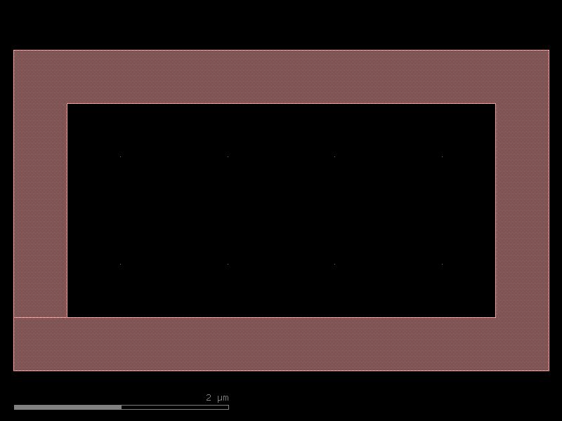
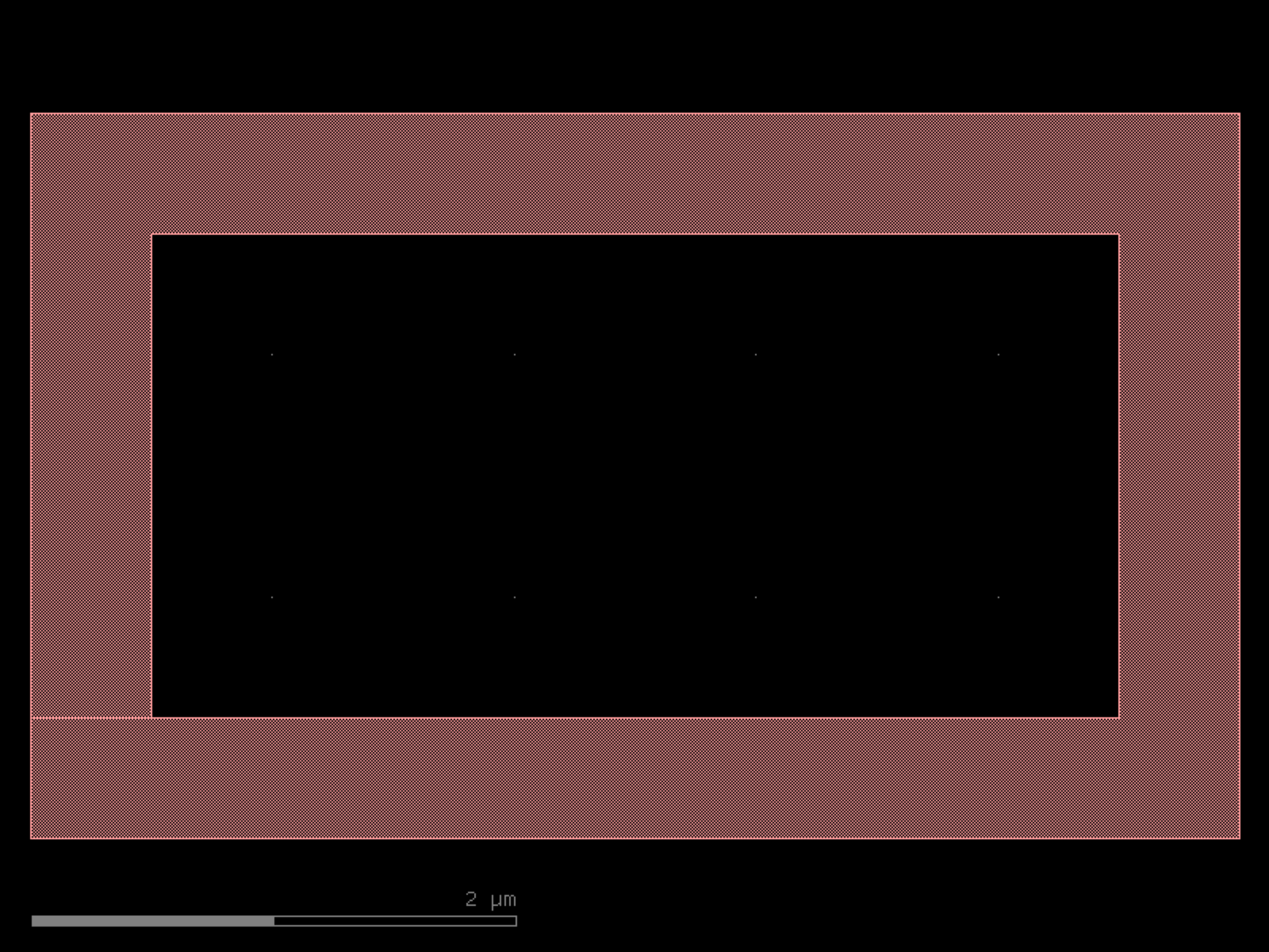

- gdsfactory.components.quantum.transmon(pad_width=200.0, pad_height=100.0, pad_gap=6.0, junction_width=0.15, junction_height=0.3, island_width=10.0, island_height=4.0, layer_metal=(1, 0), layer_junction=(2, 0), layer_island=(1, 0), port_type='electrical')[source]#
Creates a transmon qubit with Josephson junction.
A transmon qubit consists of two capacitor pads connected by a Josephson junction. The junction creates an anharmonic oscillator that can be used as a qubit.
- Parameters:
pad_width (float) – Width of each capacitor pad in μm.
pad_height (float) – Height of each capacitor pad in μm.
pad_gap (float) – Gap between the two pads in μm.
junction_width (float) – Width of the Josephson junction in μm.
junction_height (float) – Height of the Josephson junction in μm.
island_width (float) – Width of the central island in μm.
island_height (float) – Height of the central island in μm.
layer_metal (LayerSpec) – Layer for the metal pads.
layer_junction (LayerSpec) – Layer for the Josephson junction.
layer_island (LayerSpec) – Layer for the central island.
port_type (str) – Type of port to add to the component.
- Returns:
A gdsfactory component with the transmon geometry.
- Return type:
import gdsfactory as gf
gf.gpdk.PDK.activate()
c = gf.components.transmon(pad_width=200, pad_height=100, pad_gap=6, junction_width=0.15, junction_height=0.3, island_width=10, island_height=4, layer_metal=(1, 0), layer_junction=(2, 0), layer_island=(1, 0), port_type='electrical').copy()
c.draw_ports()
c.plot()
(Source code, png, hires.png, pdf)
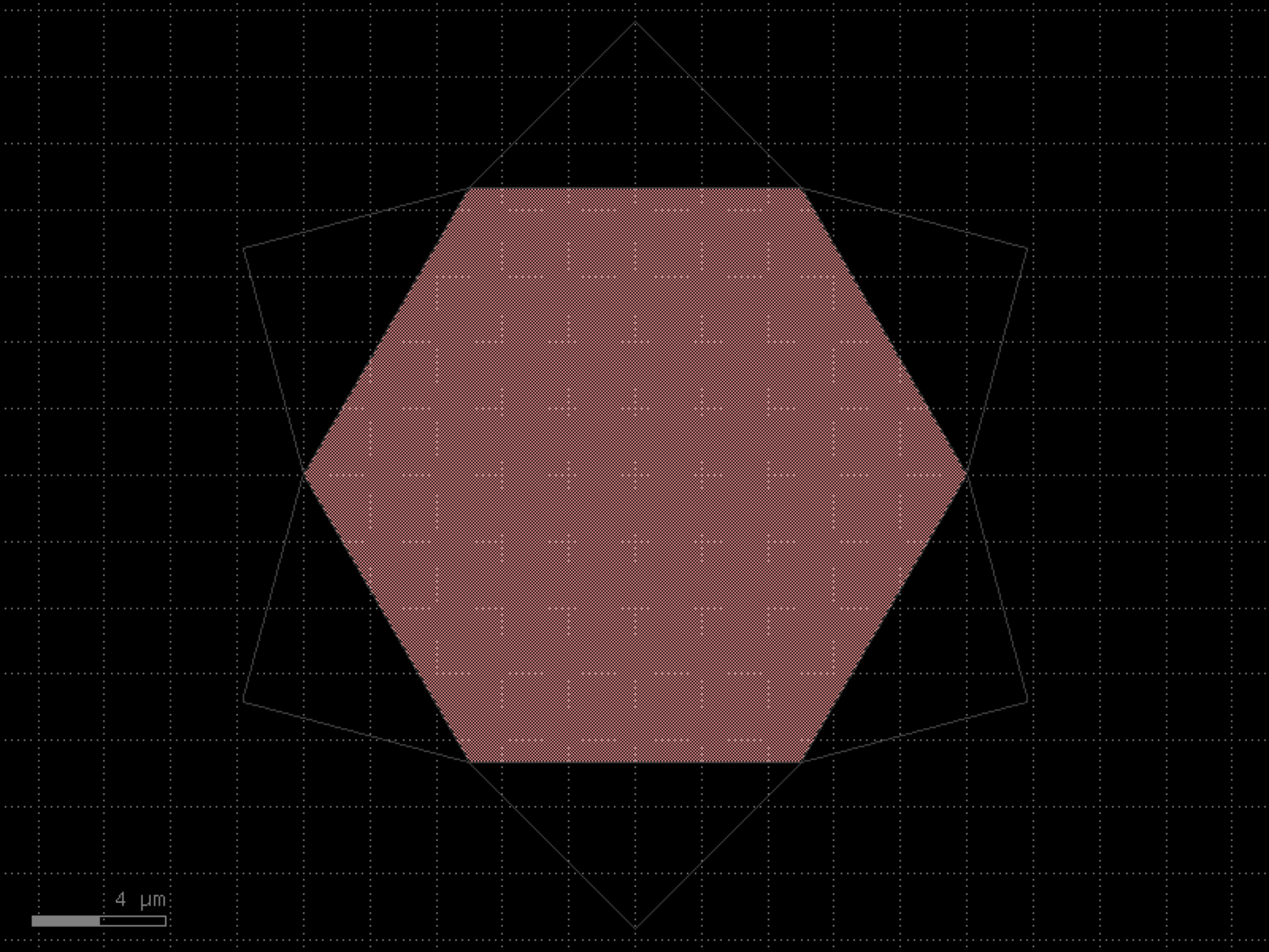

- gdsfactory.components.quantum.transmon_circular(pad_radius=100.0, pad_gap=6.0, junction_width=0.15, junction_height=0.3, island_radius=5.0, layer_metal=(1, 0), layer_junction=(2, 0), layer_island=(1, 0), port_type='electrical')[source]#
Creates a circular transmon qubit with Josephson junction.
A circular variant of the transmon qubit with circular capacitor pads.
- Parameters:
pad_radius (float) – Radius of each circular capacitor pad in μm.
pad_gap (float) – Gap between the two pads in μm.
junction_width (float) – Width of the Josephson junction in μm.
junction_height (float) – Height of the Josephson junction in μm.
island_radius (float) – Radius of the central circular island in μm.
layer_metal (LayerSpec) – Layer for the metal pads.
layer_junction (LayerSpec) – Layer for the Josephson junction.
layer_island (LayerSpec) – Layer for the central island.
port_type (str) – Type of port to add to the component.
- Returns:
A gdsfactory component with the circular transmon geometry.
- Return type:
import gdsfactory as gf
gf.gpdk.PDK.activate()
c = gf.components.transmon_circular(pad_radius=100, pad_gap=6, junction_width=0.15, junction_height=0.3, island_radius=5, layer_metal=(1, 0), layer_junction=(2, 0), layer_island=(1, 0), port_type='electrical').copy()
c.draw_ports()
c.plot()
(Source code, png, hires.png, pdf)
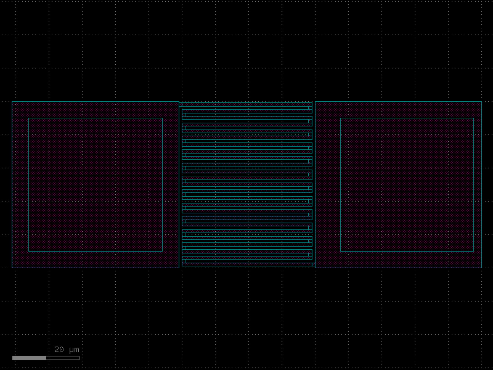
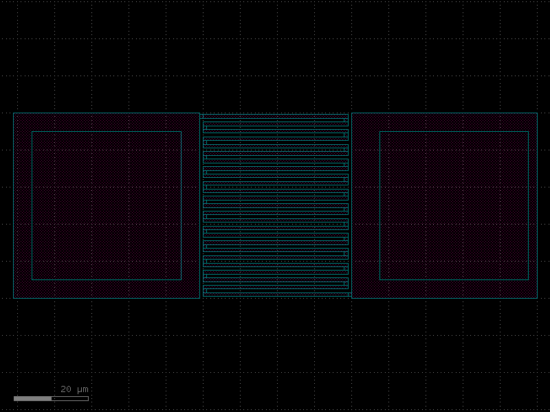
rings#
- gdsfactory.components.rings.coupler_bend(radius=None, coupler_gap=0.2, coupling_angle_coverage=120.0, cross_section_inner='strip', cross_section_outer='strip', bend=<function bend_circular_all_angle>, bend_output='bend_euler')[source]#
Compact curved coupler with bezier escape.
TODO: fix for euler bends.
- Parameters:
radius (float | None) – um.
coupler_gap (float) – um.
coupling_angle_coverage (float) – degrees.
cross_section_inner (CrossSectionSpec) – spec inner bend.
cross_section_outer (CrossSectionSpec) – spec outer bend.
bend (Callable[[...], Component | ComponentAllAngle]) – for bend.
bend_output (ComponentSpec) – for bend.
- Return type:
r 4 | | | / ___3 | / / 2____/ / 1_____/
import gdsfactory as gf
gf.gpdk.PDK.activate()
c = gf.components.coupler_bend(coupler_gap=0.2, coupling_angle_coverage=120, cross_section_inner='strip', cross_section_outer='strip', bend_output='bend_euler').copy()
c.draw_ports()
c.plot()
(Source code, png, hires.png, pdf)
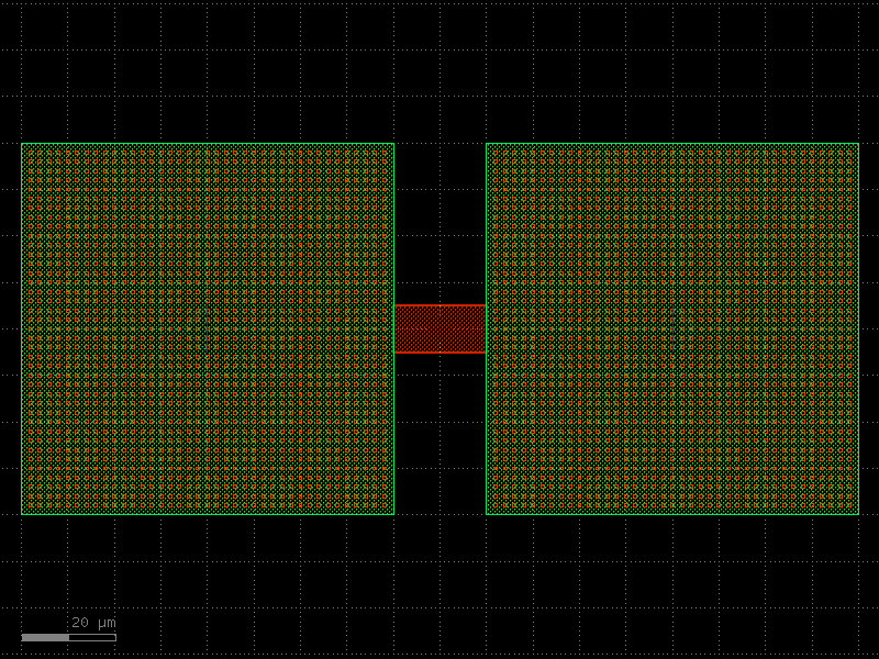
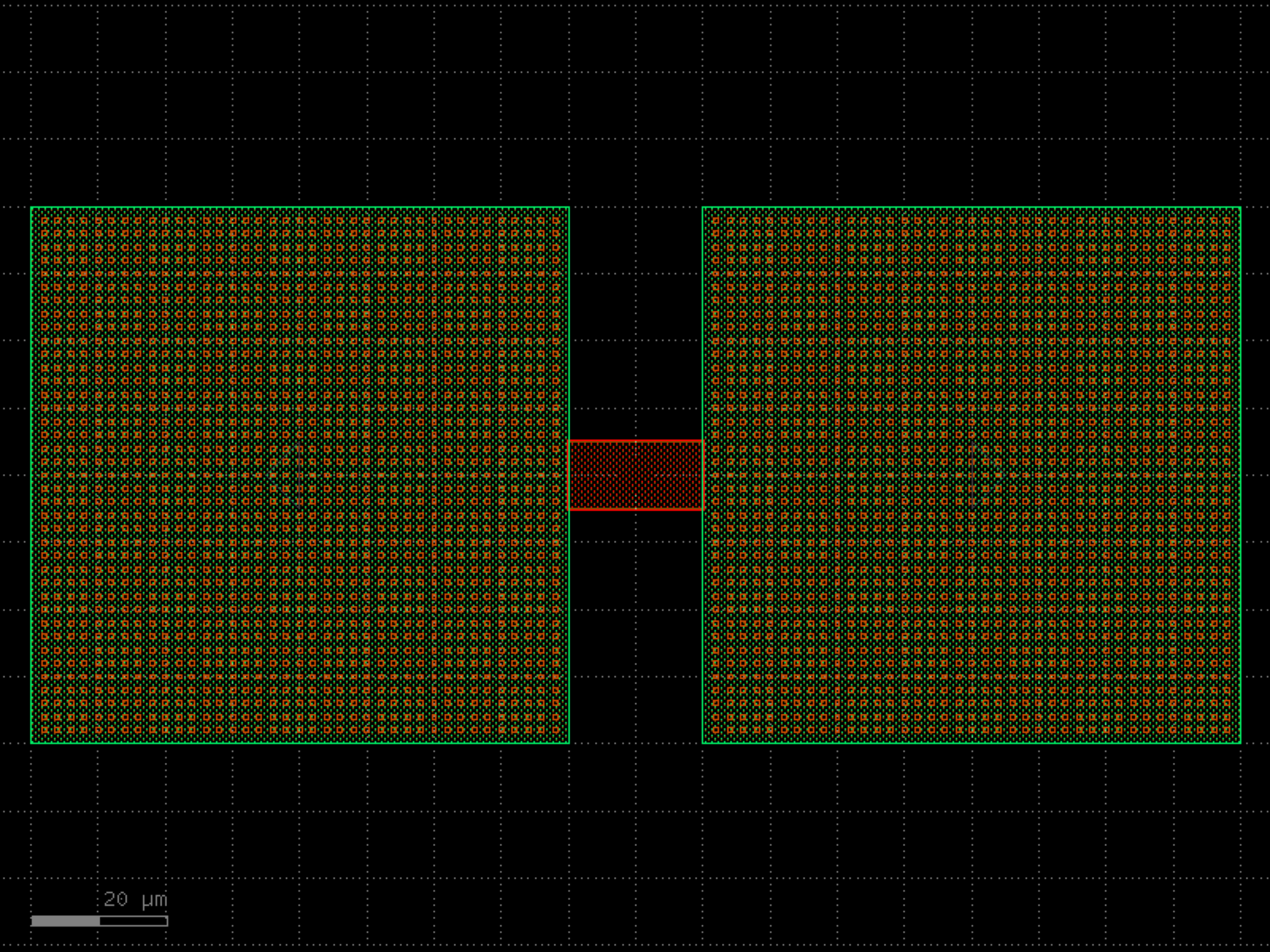

- gdsfactory.components.rings.coupler_ring_bend(radius=None, coupler_gap=0.2, coupling_angle_coverage=90.0, length_x=0.0, cross_section_inner='strip', cross_section_outer='strip', bend=<function bend_circular_all_angle>, bend_output='bend_euler', straight='straight')[source]#
Two back-to-back coupler_bend.
- Parameters:
radius (float | None) – um. Default is None, which uses the default radius of the cross_section.
coupler_gap (float) – um.
angle_inner – of the inner bend, from beginning to end. Depending on the bend chosen, gap may not be preserved.
angle_outer – of the outer bend, from beginning to end. Depending on the bend chosen, gap may not be preserved.
coupling_angle_coverage (float) – degrees.
length_x (float) – horizontal straight length.
cross_section_inner (CrossSectionSpec) – spec inner bend.
cross_section_outer (CrossSectionSpec) – spec outer bend.
bend (Callable[[...], Component | ComponentAllAngle]) – for bend.
bend_output (ComponentSpec) – for bend.
straight (ComponentSpec) – for straight.
- Return type:
import gdsfactory as gf
gf.gpdk.PDK.activate()
c = gf.components.coupler_ring_bend(coupler_gap=0.2, coupling_angle_coverage=90, length_x=0, cross_section_inner='strip', cross_section_outer='strip', bend_output='bend_euler', straight='straight').copy()
c.draw_ports()
c.plot()
(Source code, png, hires.png, pdf)
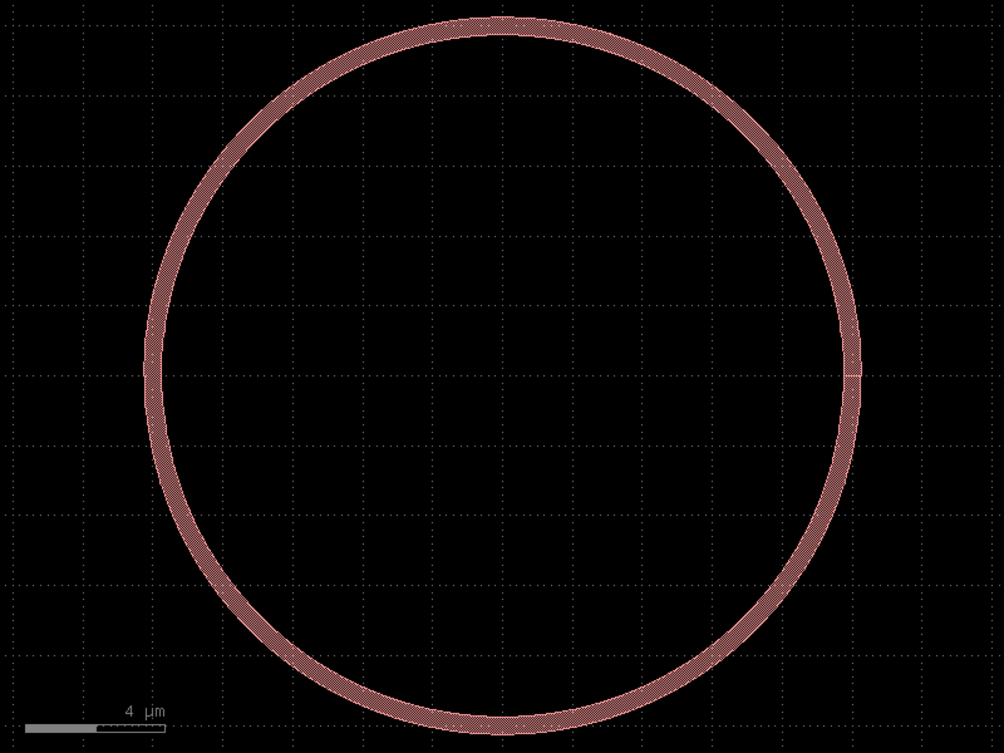
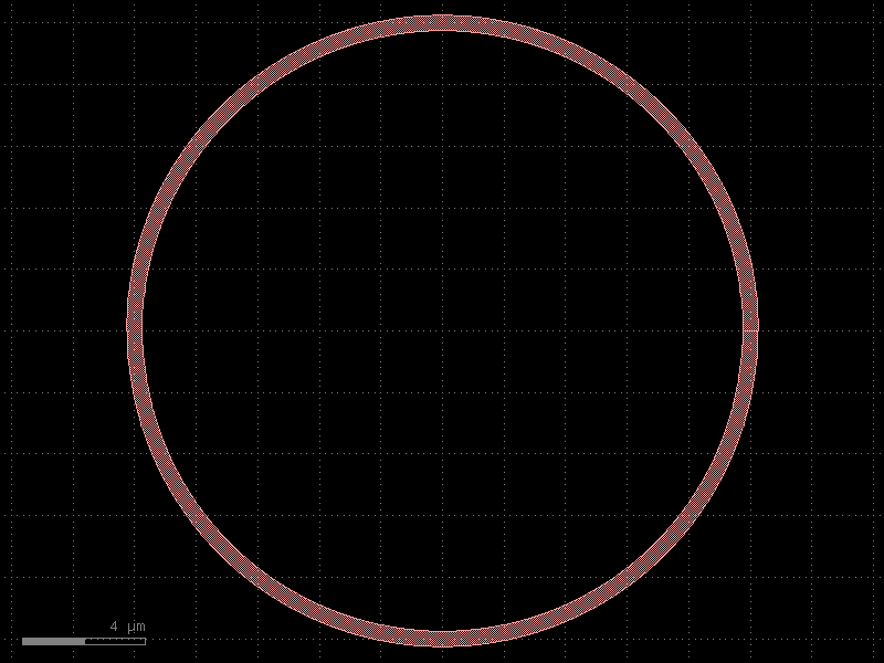
- gdsfactory.components.rings.disk(radius=10.0, gap=0.2, wrap_angle_deg=180.0, parity=1, cross_section='strip')[source]#
Disk Resonator.
- Parameters:
radius (float) – disk resonator radius.
gap (float) – Distance between the bus straight and resonator.
wrap_angle_deg (float) – Angle in degrees between 0 and 180. determines how much the bus straight wraps along the resonator. 0 corresponds to a straight bus straight. 180 corresponds to a bus straight wrapped around half of the resonator.
parity (1 or -1) – 1, resonator left from bus straight, -1 resonator to the right.
cross_section (CrossSectionSpec) – cross_section spec.
- Return type:
import gdsfactory as gf
gf.gpdk.PDK.activate()
c = gf.components.disk(radius=10, gap=0.2, wrap_angle_deg=180, parity=1, cross_section='strip').copy()
c.draw_ports()
c.plot()
(Source code, png, hires.png, pdf)
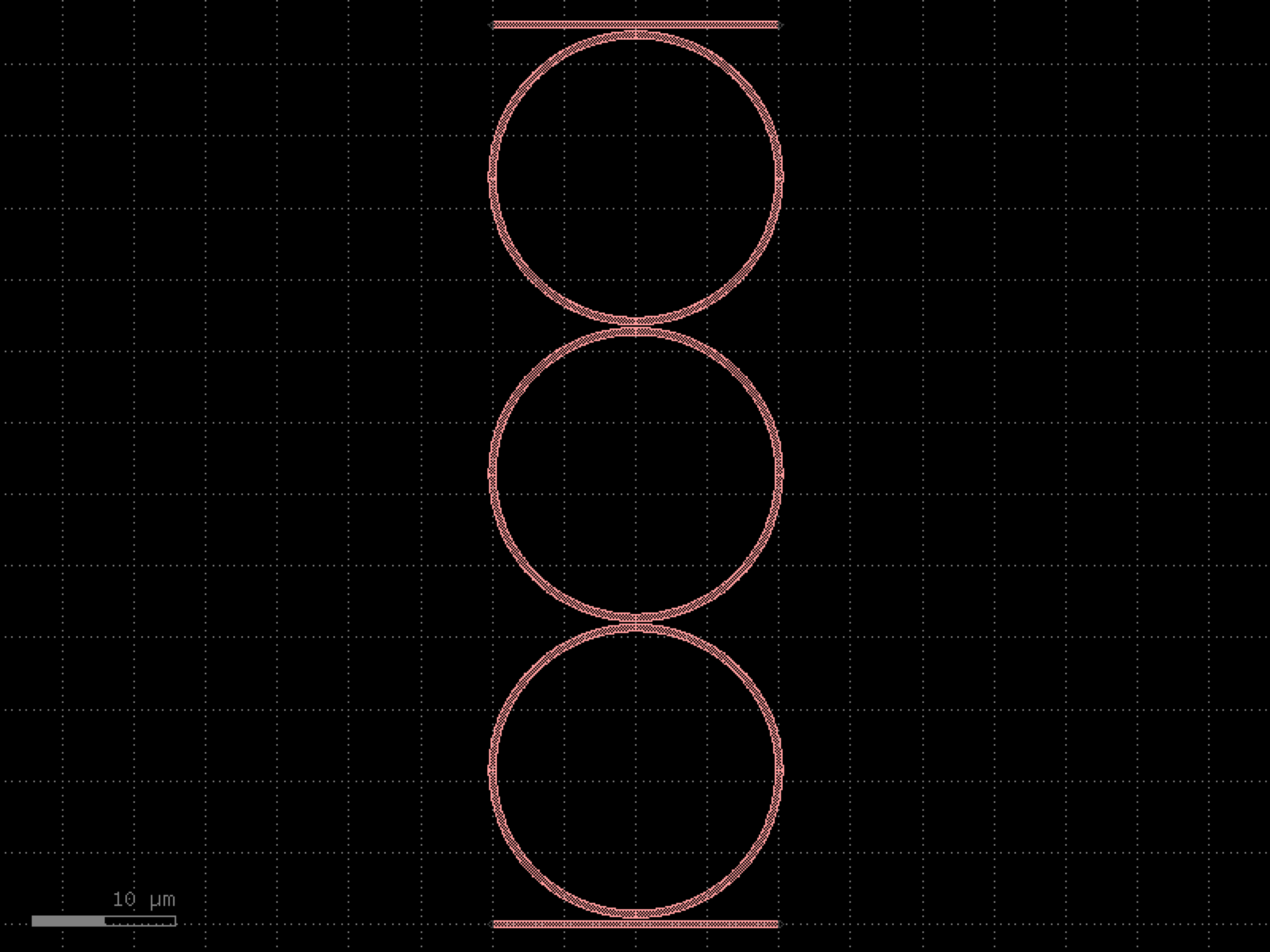
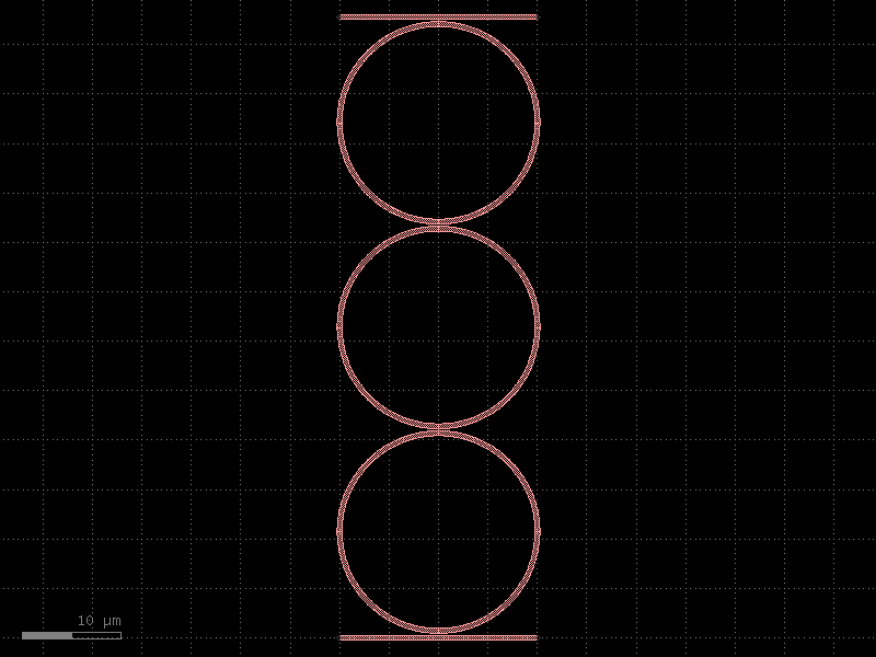
- gdsfactory.components.rings.disk_heater(radius=10.0, gap=0.2, wrap_angle_deg=180.0, parity=1, cross_section='strip', heater_layer='HEATER', via_stack='via_stack_heater_mtop', heater_width=5.0, heater_extent=2.0, via_width=10.0, port_orientation=90)[source]#
Disk Resonator with top metal heater.
- Parameters:
radius (float) – disk resonator radius.
gap (float) – Distance between the bus straight and resonator.
wrap_angle_deg (float) – Angle in degrees between 0 and 180. determines how much the bus straight wraps along the resonator. 0 corresponds to a straight bus straight. 180 corresponds to a bus straight wrapped around half of the resonator.
parity (1 or -1) – 1, resonator left from bus straight, -1 resonator to the right.
cross_section (CrossSectionSpec) – cross_section spec.
heater_layer (LayerSpec) – layer of the heater.
via_stack (ComponentSpec) – via stack component.
heater_width (float) – width of the heater.
heater_extent (float) – length of heater beyond disk.
via_width (float) – size of the square via at the end of the heater.
port_orientation (float | None) – in degrees.
- Return type:
import gdsfactory as gf
gf.gpdk.PDK.activate()
c = gf.components.disk_heater(radius=10, gap=0.2, wrap_angle_deg=180, parity=1, cross_section='strip', heater_layer='HEATER', via_stack='via_stack_heater_mtop', heater_width=5, heater_extent=2, via_width=10, port_orientation=90).copy()
c.draw_ports()
c.plot()
(Source code, png, hires.png, pdf)
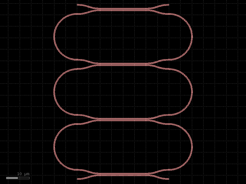
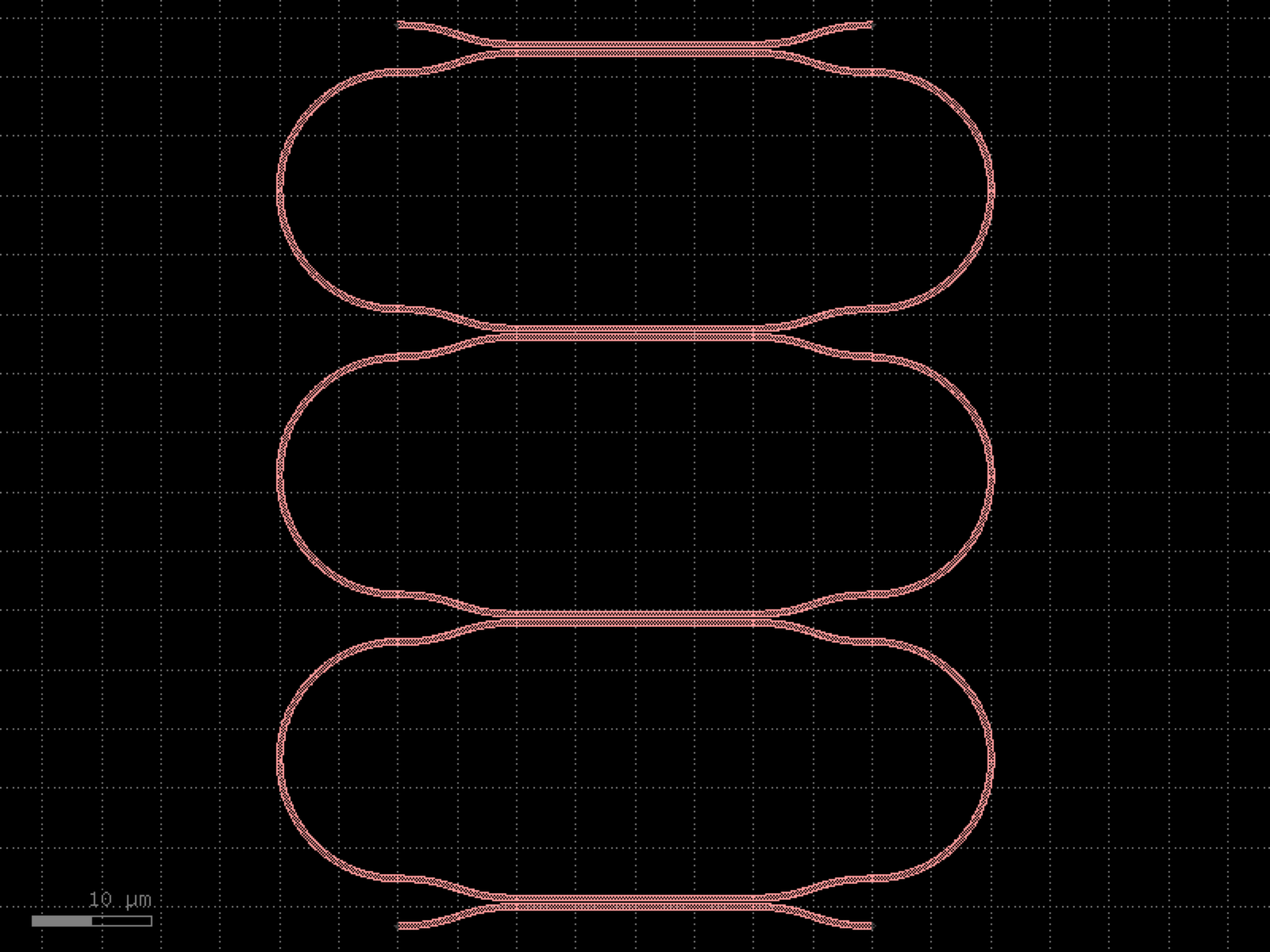

- gdsfactory.components.rings.ring(radius=10.0, width=0.5, angle_resolution=2.5, layer='WG', angle=360, distance_resolution=None)[source]#
Returns a ring.
- Parameters:
radius (float) – ring radius.
width (float) – of the ring.
angle_resolution (float) – max number of degrees per point.
layer (LayerSpec) – layer.
angle (float) – angular coverage of the ring
distance_resolution (float | None) – max distance between points. This is an alternate way to describe the resolution besides setting angle_resolution. If distance_resolution and angle_resolution are both set, distance_resolution determines the resolution.
- Return type:
import gdsfactory as gf
gf.gpdk.PDK.activate()
c = gf.components.ring(radius=10, width=0.5, angle_resolution=2.5, layer='WG', angle=360).copy()
c.draw_ports()
c.plot()
(Source code, png, hires.png, pdf)
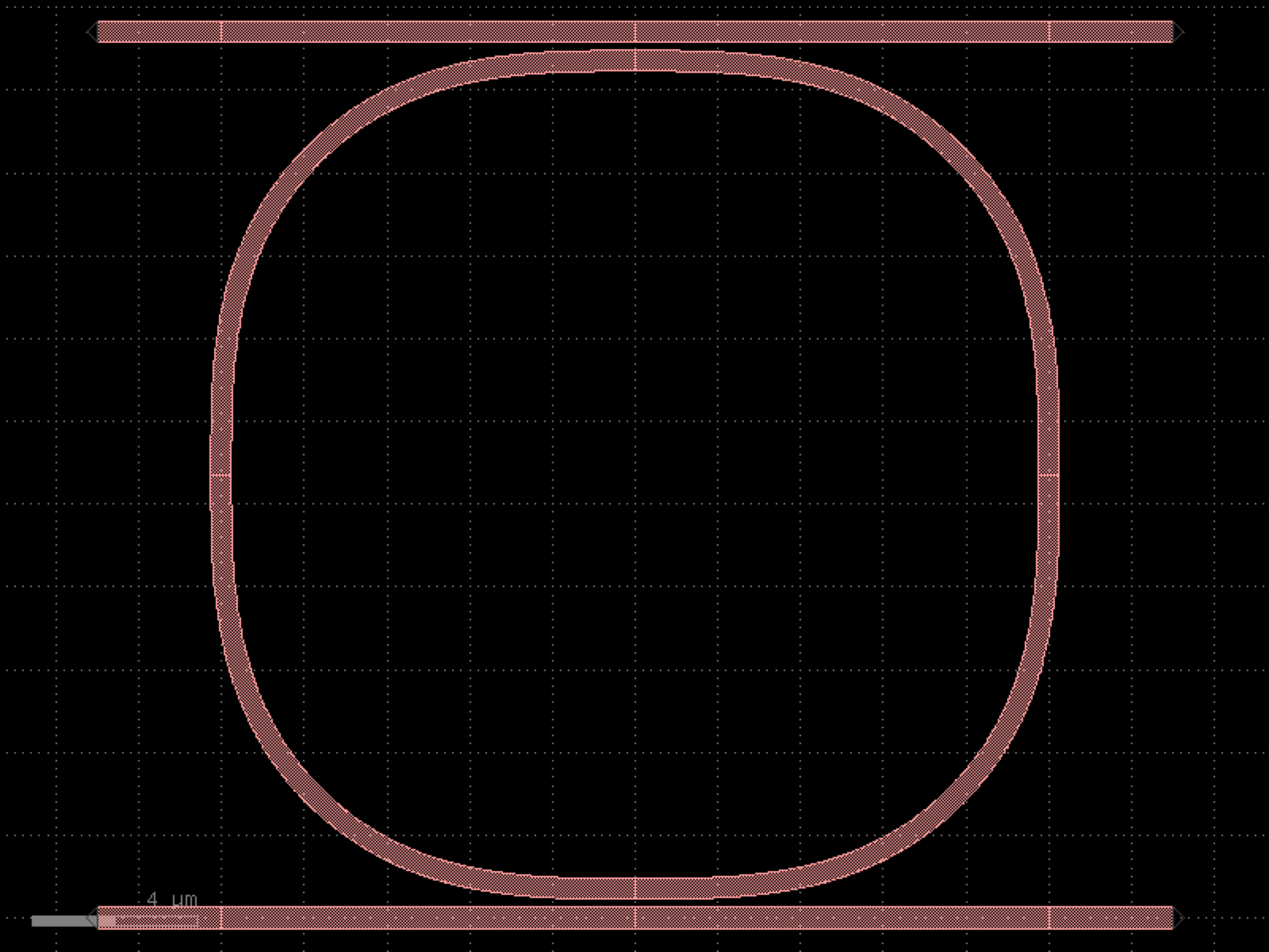
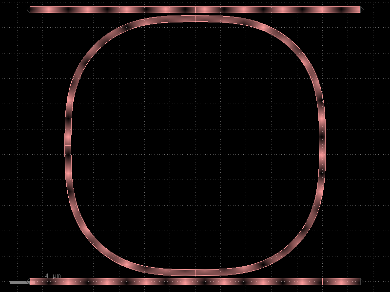
- gdsfactory.components.rings.ring_asymmetric(radius=10.0, length_x=2.0, length_y=4.0, straight='straight', bend='bend_circular', cross_section='strip')[source]#
An asymmetric ring with straight waveguides between the bends.
- Parameters:
radius (float) – of the ring.
length_x (float) – horizontal straight length.
length_y (float) – vertical straight length.
straight (ComponentSpec) – straight component spec.
bend (ComponentSpec) – bend component spec.
cross_section (CrossSectionSpec) – cross_section spec.
- Return type:
import gdsfactory as gf
gf.gpdk.PDK.activate()
c = gf.components.ring_asymmetric(radius=10, length_x=2, length_y=4, straight='straight', bend='bend_circular', cross_section='strip').copy()
c.draw_ports()
c.plot()
(Source code, png, hires.png, pdf)
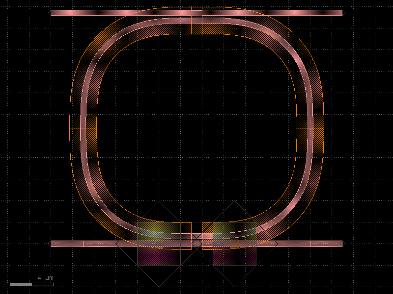
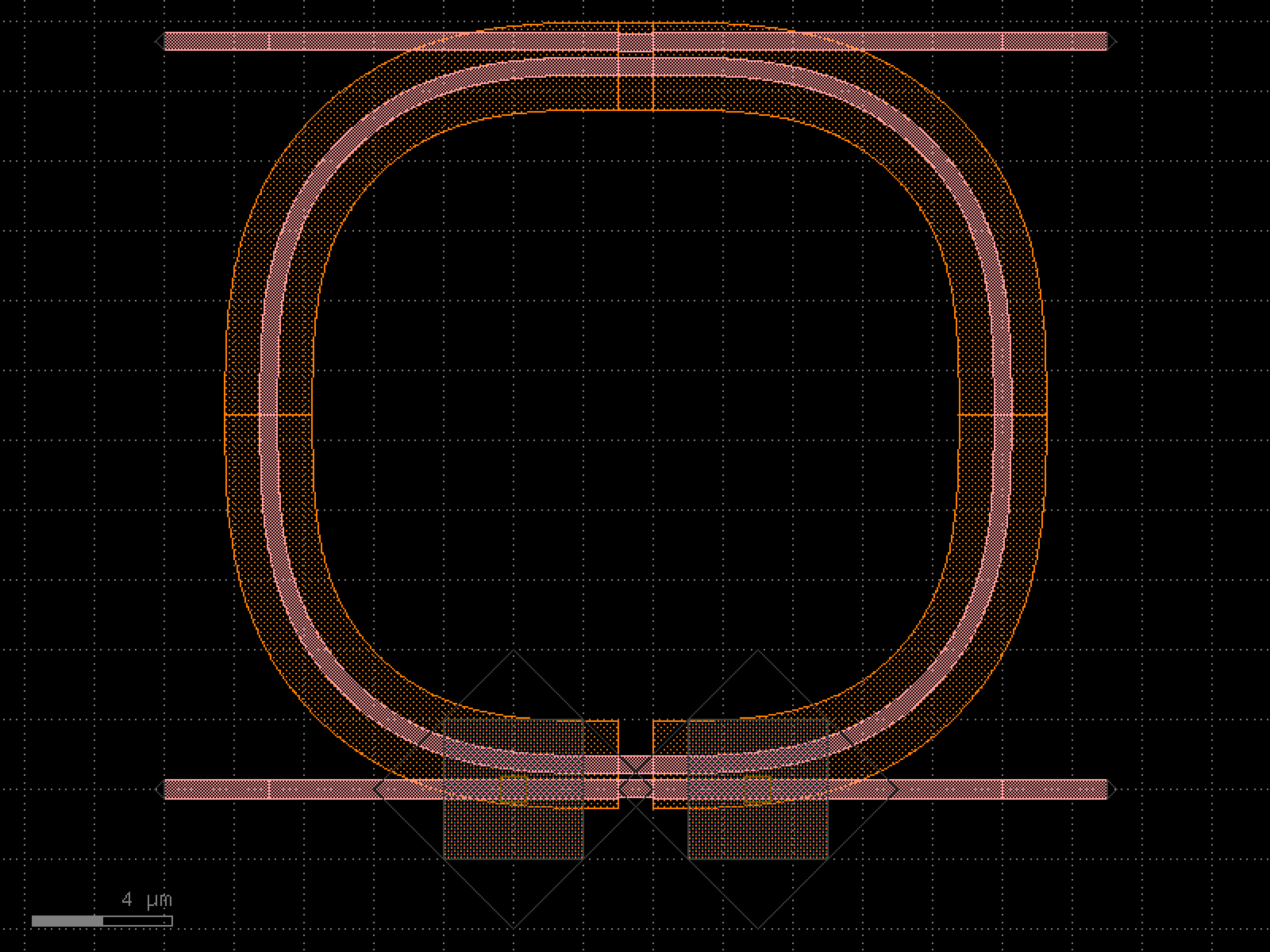

- gdsfactory.components.rings.ring_crow(gaps=(0.2, 0.2, 0.2, 0.2), radius=(10.0, 10.0, 10.0), bends=None, ring_cross_sections=('strip', 'strip', 'strip'), length_x=0, lengths_y=(0, 0, 0), input_straight_cross_section=None, output_straight_cross_section=None, cross_section='strip')[source]#
Coupled ring resonators.
- Parameters:
gaps (tuple[float, ...]) – gap between rings.
radius (tuple[float, ...]) – for each ring.
bends (tuple[ComponentSpec, ...] | None) – bend spec for each ring.
ring_cross_sections (tuple[CrossSectionSpec, ...]) – cross_section spec for each ring.
length_x (float) – ring coupler length.
lengths_y (tuple[float, ...]) – vertical straight length.
input_straight_cross_section (CrossSectionSpec | None) – cross_section spec for input and output straight. Defaults to cross_section.
output_straight_cross_section (CrossSectionSpec | None) – cross_section spec for input and output straight. Defaults to cross_section.
cross_section (CrossSectionSpec) – cross_section spec for input and output straight.
- Return type:
--==ct==-- gap[N-1] | | sl sr ring[N-1] | | --==cb==-- gap[N-2] . . . --==ct==-- | | sl sr lengths_y[1], ring[1] | | --==cb==-- gap[1] --==ct==-- | | sl sr lengths_y[0], ring[0] | | --==cb==-- gap[0] length_x
import gdsfactory as gf
gf.gpdk.PDK.activate()
c = gf.components.ring_crow(gaps=(0.2, 0.2, 0.2, 0.2), radius=(10, 10, 10), ring_cross_sections=('strip', 'strip', 'strip'), length_x=0, lengths_y=(0, 0, 0), cross_section='strip').copy()
c.draw_ports()
c.plot()
(Source code, png, hires.png, pdf)
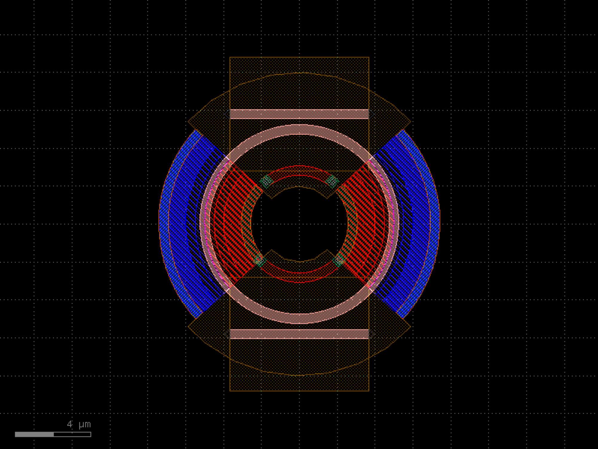
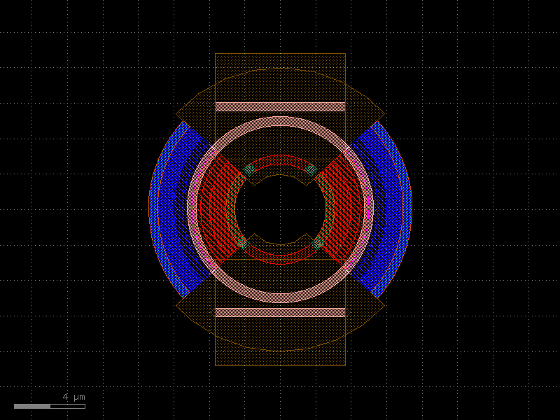
- gdsfactory.components.rings.ring_crow_couplers(radius=(10.0, 10.0, 10.0), bends=('bend_circular', 'bend_circular', 'bend_circular'), ring_cross_sections=('strip', 'strip', 'strip'), couplers=('coupler', 'coupler', 'coupler', 'coupler'))[source]#
Coupled ring resonators with coupler components between gaps.
- Parameters:
radius (Sequence[float]) – for the bend and coupler.
bends (Sequence[ComponentSpec]) – bend specs.
ring_cross_sections (Sequence[CrossSectionSpec]) – cross_section for the ring.
couplers (Sequence[ComponentSpec]) – coupling component between rings and bus.
- Return type:
--==ct==-- gap[N-1] <------- couplers[N-1] | | sl sr ring[N-1] | | --==cb==-- gap[N-2] <------- couplers[N-2] . . . --==ct==-- | | sl sr lengths_y[1], ring[1] | | --==cb==-- gap[1] <------- couplers[1] --==ct==-- | | sl sr lengths_y[0], ring[0] | | --==cb==-- gap[0] <------- couplers[0] length_x
import gdsfactory as gf
gf.gpdk.PDK.activate()
c = gf.components.ring_crow_couplers(radius=(10, 10, 10), bends=('bend_circular', 'bend_circular', 'bend_circular'), ring_cross_sections=('strip', 'strip', 'strip'), couplers=('coupler', 'coupler', 'coupler', 'coupler')).copy()
c.draw_ports()
c.plot()
(Source code, png, hires.png, pdf)
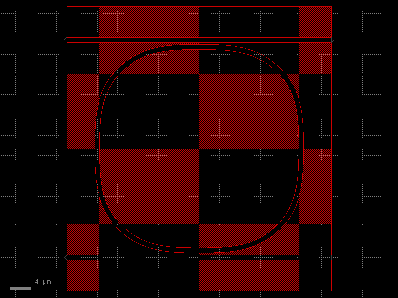
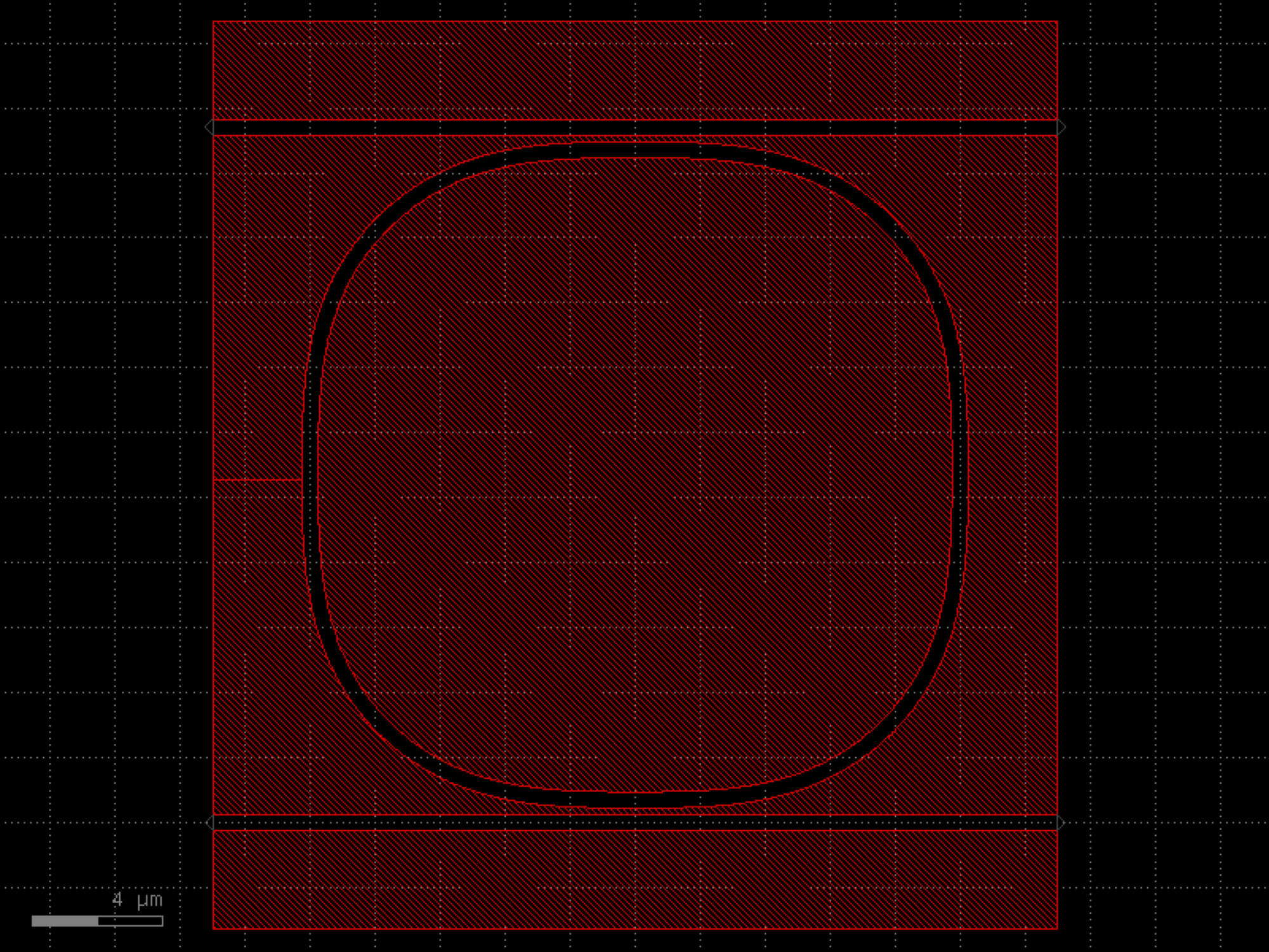

- gdsfactory.components.rings.ring_double(gap=0.2, gap_top=None, gap_bot=None, radius=None, length_x=0.01, length_y=0.01, bend='bend_euler', straight='straight', coupler_ring='coupler_ring', coupler_ring_top=None, cross_section='strip', length_extension=None)[source]#
Returns a double bus ring.
two couplers (ct: top, cb: bottom) connected with two vertical straights (sl: left, sr: right)
- Parameters:
gap (float) – gap between for coupler.
gap_top (float | None) – gap for the top coupler. Defaults to gap.
gap_bot (float | None) – gap for the bottom coupler. Defaults to gap.
radius (float | None) – for the bend and coupler.
length_x (float) – ring coupler length.
length_y (float) – vertical straight length.
bend (ComponentSpec) – 90 degrees bend spec.
straight (ComponentSpec) – straight spec.
coupler_ring (ComponentSpec) – ring coupler spec.
coupler_ring_top (ComponentSpec | None) – top ring coupler spec. Defaults to coupler_ring.
cross_section (CrossSectionSpec) – cross_section spec.
length_extension (float | None) – straight length extension at the end of the coupler bottom ports.
- Return type:
o2──────▲─────────o3 │gap_top xx──────▼─────────xxx xxx xxx xxx xxx xx xxx x xxx xx xx▲ xx xx│length_y xx xx▼ xx xx xx length_x x xx ◄───────────────► x xx xxx xx xxx xxx──────▲─────────xxx │gap o1──────▼─────────◄──────────────► o4 length_extension
import gdsfactory as gf
gf.gpdk.PDK.activate()
c = gf.components.ring_double(gap=0.2, length_x=0.01, length_y=0.01, bend='bend_euler', straight='straight', coupler_ring='coupler_ring', cross_section='strip').copy()
c.draw_ports()
c.plot()
(Source code, png, hires.png, pdf)
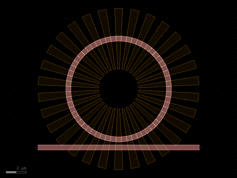
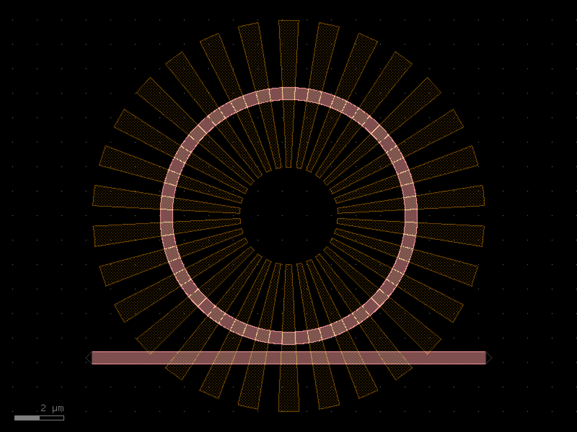

- gdsfactory.components.rings.ring_double_bend_coupler(radius=5.0, gap=0.2, coupling_angle_coverage=70.0, bend=<function bend_circular_all_angle>, length_x=0.6, length_y=0.6, cross_section_inner='strip', cross_section_outer='strip')[source]#
Returns ring with double curved couplers.
- Parameters:
radius (float) – um.
gap (float) – um.
coupling_angle_coverage (float) – degrees.
bend (Callable[[...], ComponentAllAngle]) – for bend.
length_x (float) – horizontal straight length.
length_y (float) – vertical straight length.
cross_section_inner (CrossSectionSpec) – spec inner bend.
cross_section_outer (CrossSectionSpec) – spec outer bend.
- Return type:
import gdsfactory as gf
gf.gpdk.PDK.activate()
c = gf.components.ring_double_bend_coupler(radius=5, gap=0.2, coupling_angle_coverage=70, length_x=0.6, length_y=0.6, cross_section_inner='strip', cross_section_outer='strip').copy()
c.draw_ports()
c.plot()
(Source code, png, hires.png, pdf)
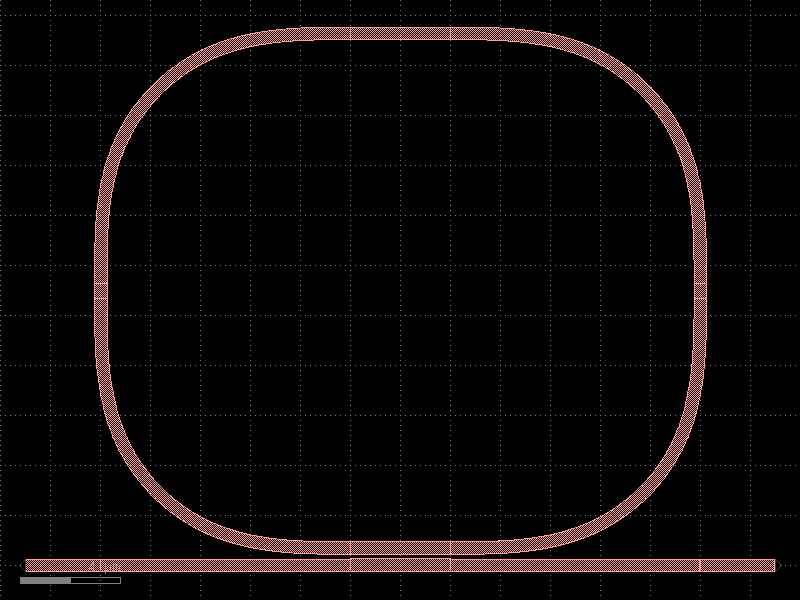
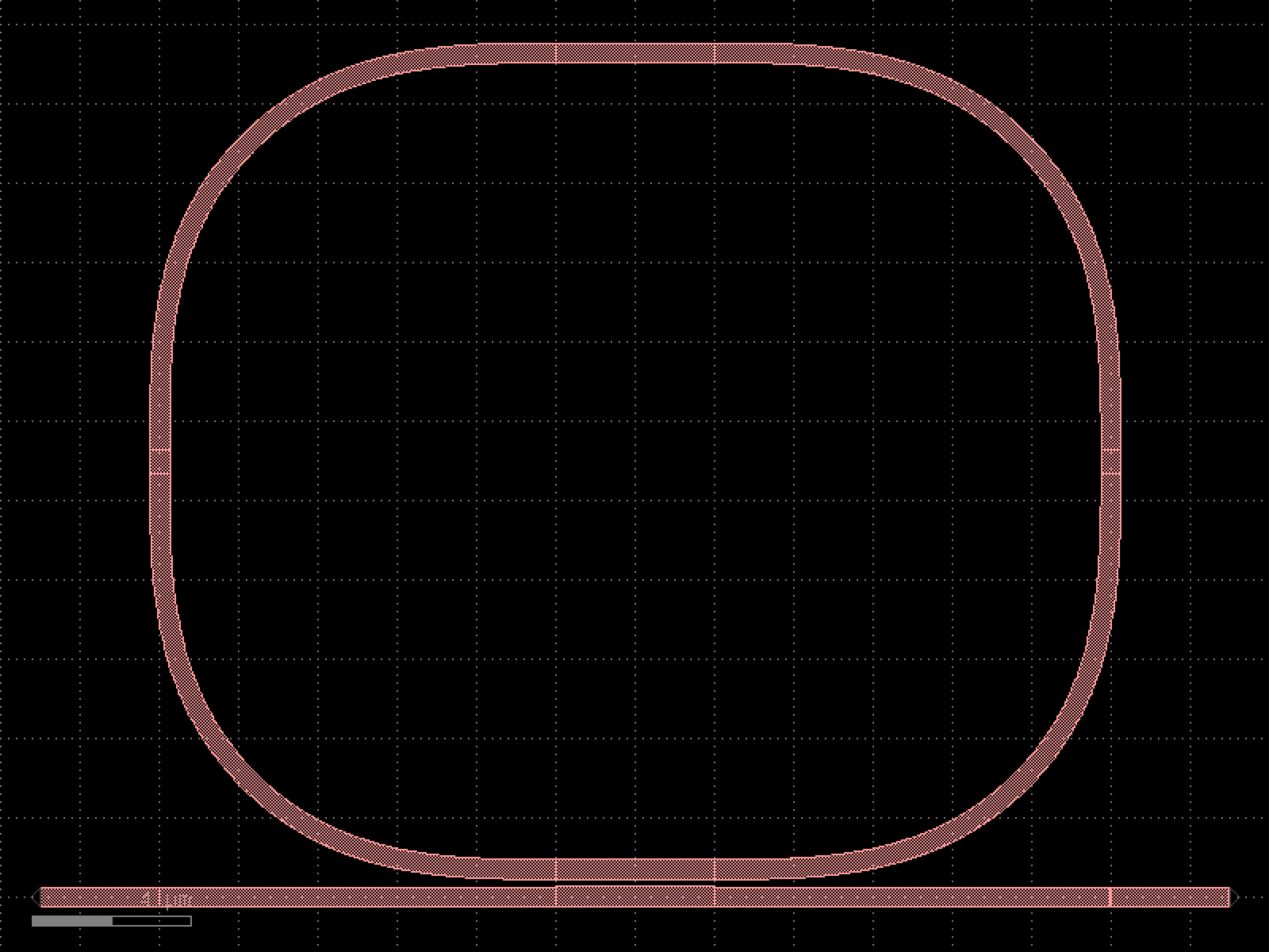

- gdsfactory.components.rings.ring_double_heater(gap=0.2, gap_top=None, gap_bot=None, radius=None, length_x=1.0, length_y=0.01, coupler_ring='coupler_ring', coupler_ring_top=None, straight='straight', bend='bend_euler', cross_section_heater='heater_metal', cross_section_waveguide_heater='strip_heater_metal', cross_section='strip', via_stack='via_stack_heater_mtop_mini', port_orientation=None, via_stack_offset=(1, 0), via_stack_size=None, with_drop=True, length_extension=None, length_extension_top=None, length_extension_bot=None)[source]#
Returns a double bus ring with heater on top.
two couplers (ct: top, cb: bottom) connected with two vertical straights (sl: left, sr: right)
- Parameters:
gap (float) – gap between for coupler.
gap_top (float | None) – gap for the top coupler. Defaults to gap.
gap_bot (float | None) – gap for the bottom coupler. Defaults to gap.
radius (float | None) – for the bend and coupler.
length_x (float) – ring coupler length.
length_y (float) – vertical straight length.
coupler_ring (ComponentSpec) – ring coupler spec.
coupler_ring_top (ComponentSpec | None) – ring coupler spec for coupler away from vias (defaults to coupler_ring)
straight (ComponentSpec) – straight spec.
bend (ComponentSpec) – bend spec.
cross_section_heater (CrossSectionSpec) – for heater.
cross_section_waveguide_heater (CrossSectionSpec) – for waveguide with heater.
cross_section (CrossSectionSpec) – for regular waveguide.
via_stack (ComponentSpec) – for heater to routing metal.
port_orientation (AngleInDegrees | None) – for electrical ports to promote from via_stack.
via_stack_size (Float2 | None) – size of via_stack.
via_stack_offset (Float2) – x,y offset for via_stack.
with_drop (bool) – adds drop ports.
length_extension (float | None) – straight length extension at the end of the coupler bottom ports.
length_extension_top (float | None) – straight length extension at the end of the coupler top ports.
length_extension_bot (float | None) – straight length extension at the end of the coupler bottom ports.
- Return type:
o2──────▲─────────o3 │gap_top xx──────▼─────────xxx xxx xxx xxx xxx xx xxx x xxx xx xx▲ xx xx│length_y xx xx▼ xx xx xx length_x x xx ◄───────────────► x xx xxx xx xxx xxx──────▲─────────xxx │gap o1──────▼─────────o4
import gdsfactory as gf
gf.gpdk.PDK.activate()
c = gf.components.ring_double_heater(gap=0.2, length_x=1, length_y=0.01, coupler_ring='coupler_ring', straight='straight', bend='bend_euler', cross_section_heater='heater_metal', cross_section_waveguide_heater='strip_heater_metal', cross_section='strip', via_stack='via_stack_heater_mtop_mini', via_stack_offset=(1, 0), with_drop=True).copy()
c.draw_ports()
c.plot()
(Source code, png, hires.png, pdf)
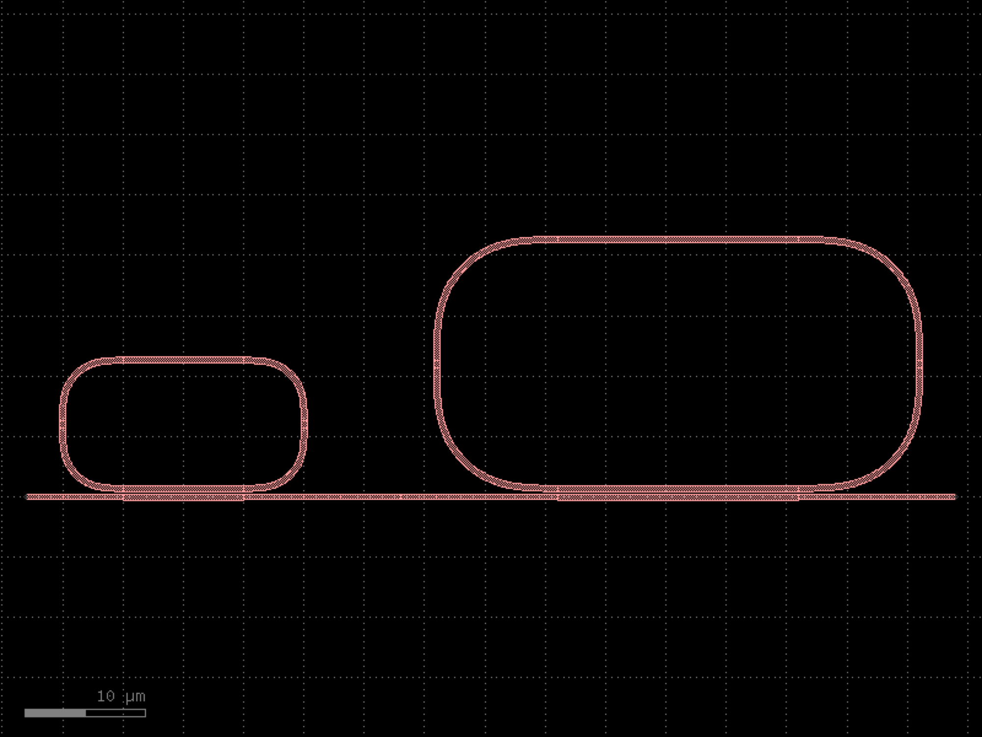
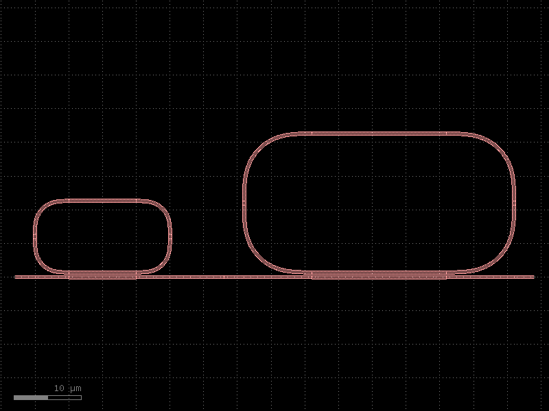
- gdsfactory.components.rings.ring_double_pn(add_gap=0.3, drop_gap=0.3, radius=5.0, doping_angle=85, cross_section=<function rib>, pn_cross_section=functools.partial(<function pn>, width_doping=2.425, width_slab=4.85, layer_via='VIAC', width_via=0.5, layer_metal='M1', width_metal=0.5), doped_heater=True, doped_heater_angle_buffer=10, doped_heater_layer='NPP', doped_heater_width=0.5, doped_heater_waveguide_offset=2.175, heater_vias=functools.partial(<function via_stack>, size=(0.5, 0.5), layers=('M1', 'M2', 'M3'), vias=(functools.partial(<function via>, layer='VIAC', size=(0.1, 0.1), enclosure=0.01, pitch=0.2), functools.partial(<function via>, layer='VIA1', size=(0.1, 0.1), enclosure=0.01, pitch=0.2), None), correct_size=True), with_drop=True, **kwargs)[source]#
Returns add-drop pn ring with optional doped heater.
- Parameters:
add_gap (float) – gap to add waveguide. Bottom gap.
drop_gap (float) – gap to drop waveguide. Top gap.
radius (float) – for the bend and coupler.
doping_angle (float) – angle in degrees representing portion of ring that is doped.
length_x – ring coupler length.
length_y – vertical straight length.
cross_section (CrossSectionFactory) – cross_section spec for non-PN doped rib waveguide sections.
pn_cross_section (CrossSectionFactory) – cross section of pn junction.
doped_heater (bool) – boolean for if we include doped heater or not.
doped_heater_angle_buffer (float) – angle in degrees buffering heater from pn junction.
doped_heater_layer (LayerSpec) – doping layer for heater.
doped_heater_width (float) – width of doped heater.
doped_heater_waveguide_offset (float) – distance from the center of the ring waveguide to the center of the doped heater.
heater_vias (ComponentSpec) – components specifications for heater vias
with_drop (bool) – boolean for if we include drop waveguide or not.
kwargs (Any) – cross_section settings.
- Return type:
import gdsfactory as gf
gf.gpdk.PDK.activate()
c = gf.components.ring_double_pn(add_gap=0.3, drop_gap=0.3, radius=5, doping_angle=85, doped_heater=True, doped_heater_angle_buffer=10, doped_heater_layer='NPP', doped_heater_width=0.5, doped_heater_waveguide_offset=2.175, with_drop=True).copy()
c.draw_ports()
c.plot()
(Source code, png, hires.png, pdf)
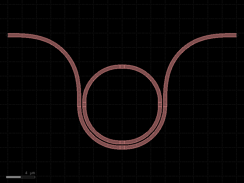
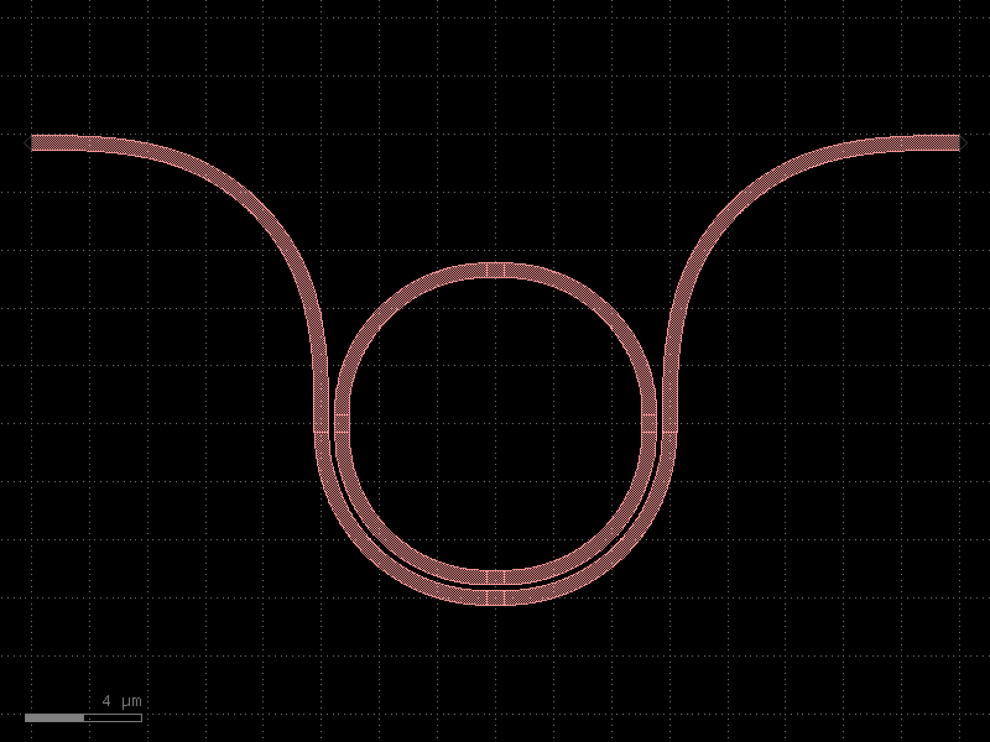

- gdsfactory.components.rings.ring_single(gap=0.2, radius=None, length_x=4.0, length_y=0.6, bend='bend_euler', straight='straight', coupler_ring='coupler_ring', cross_section='strip', length_extension=None)[source]#
Returns a single ring resonator with a directional coupler.
This component creates a ring resonator that consists of: - A directional coupler (cb) at the bottom - Two vertical straights (sl, sr) on the left and right sides - Two bends (bl, br) connecting the vertical straights - A horizontal straight (st) at the top
The ring resonator is commonly used in photonic integrated circuits for: - Wavelength filtering - Optical modulation - Sensing applications - Optical switching
- Parameters:
gap (float) – Gap between the ring and the straight waveguide in the coupler (μm).
radius (float | None) – Radius of the ring bends (μm). If None, it will use the radius from the cross section.
length_x (float) – Length of the horizontal straight section (μm).
length_y (float) – Length of the vertical straight sections (μm).
bend (ComponentSpec) – Component spec for the 90-degree bends. Default is “bend_euler”.
straight (ComponentSpec) – Component spec for the straight waveguides. Default is “straight”.
coupler_ring (ComponentSpec) – Component spec for the ring coupler. Default is “coupler_ring”.
cross_section (CrossSectionSpec) – Cross section spec for all waveguides. Default is “strip”.
length_extension (float | None) – straight length extension at the end of the coupler bottom ports.
- Returns:
- A gdsfactory Component containing the ring resonator with:
Two ports: “o1” (input) and “o2” (through)
All waveguide sections properly connected
Cross section applied to all waveguides
- Return type:
- Raises:
ValueError – If length_x or length_y is negative.
xxxxxxxxxxxxx xxxxx xxxx xxx xxx xxx xxx xx xxx x xxx xx xx▲ xx xx│length_y xx xx▼ xx xx xx length_x x xx ◄───────────────► x xx xxx xx xxx xxx──────▲─────────xxx │gap o1──────▼─────────o2◄──────────────► length_extension
import gdsfactory as gf
gf.gpdk.PDK.activate()
c = gf.components.ring_single(gap=0.2, length_x=4, length_y=0.6, bend='bend_euler', straight='straight', coupler_ring='coupler_ring', cross_section='strip').copy()
c.draw_ports()
c.plot()
(Source code, png, hires.png, pdf)
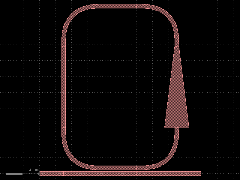
- gdsfactory.components.rings.ring_single_array(ring='ring_single', spacing=15.0, list_of_dicts=None, cross_section='strip')[source]#
Ring of single bus connected with straights.
- Parameters:
ring (ComponentSpec) – ring spec.
spacing (float) – between rings.
list_of_dicts (tuple[dict[str, Any], ...] | None) – settings for each ring.
cross_section (CrossSectionSpec) – spec.
- Return type:
______ ______ | | | | | | length_y | | | | | | --======-- spacing ----==gap==-- length_x
import gdsfactory as gf
gf.gpdk.PDK.activate()
c = gf.components.ring_single_array(ring='ring_single', spacing=15, cross_section='strip').copy()
c.draw_ports()
c.plot()
(Source code, png, hires.png, pdf)
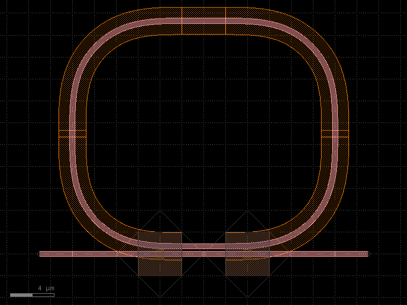
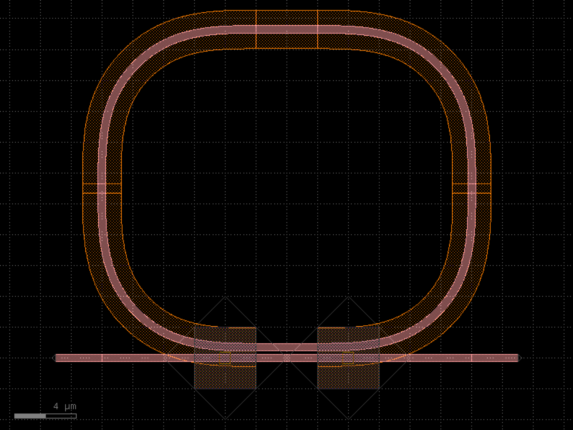

- gdsfactory.components.rings.ring_single_bend_coupler(radius=5.0, gap=0.2, coupling_angle_coverage=180.0, bend_all_angle=<function bend_circular_all_angle>, bend='bend_circular', bend_output='bend_euler', length_x=0.6, length_y=0.6, cross_section_inner='strip', cross_section_outer='strip', **kwargs)[source]#
Returns ring with curved coupler.
TODO: enable euler bends.
- Parameters:
radius (float) – um.
gap (float) – um.
coupling_angle_coverage (float) – degrees.
angle_inner – of the inner bend, from beginning to end. Depending on the bend chosen, gap may not be preserved.
angle_outer – of the outer bend, from beginning to end. Depending on the bend chosen, gap may not be preserved.
bend_all_angle (Callable[[...], Component | ComponentAllAngle]) – for bend.
bend (ComponentSpec) – for bend.
bend_output (ComponentSpec) – for bend.
length_x (float) – horizontal straight length.
length_y (float) – vertical straight length.
cross_section_inner (CrossSectionSpec) – spec inner bend.
cross_section_outer (CrossSectionSpec) – spec outer bend.
kwargs (Any) – cross_section settings.
- Return type:
import gdsfactory as gf
gf.gpdk.PDK.activate()
c = gf.components.ring_single_bend_coupler(radius=5, gap=0.2, coupling_angle_coverage=180, bend='bend_circular', bend_output='bend_euler', length_x=0.6, length_y=0.6, cross_section_inner='strip', cross_section_outer='strip').copy()
c.draw_ports()
c.plot()
(Source code, png, hires.png, pdf)
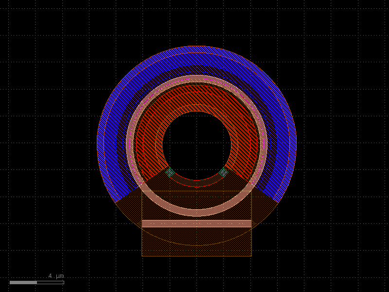
- gdsfactory.components.rings.ring_single_dut(component='straight', gap=0.2, length_x=4, length_y=0, radius=None, coupler='coupler_ring', bend='bend_euler', with_component=True, port_name='o1', length_extension=None, **kwargs)[source]#
Single bus ring made of two couplers (ct: top, cb: bottom) connected.
with two vertical straights (wyl: left, wyr: right) (Component Under Test) in the middle to extract loss from quality factor.
- Parameters:
component (ComponentSpec) – device under test.
gap (float) – in um.
length_x (float) – in um.
length_y (float) – in um.
radius (float | None) – in um. Default is None, which uses the default radius of the cross_section.
coupler (ComponentSpec) – coupler function.
bend (ComponentSpec) – bend function.
with_component (bool) – True adds component. False adds waveguide.
port_name (str) – for component input.
length_extension (float | None) – optional length extension for the coupler bottom ports.
kwargs (Any) – cross_section settings.
with_component – if False changes component for just a straight.
- Return type:
bl-wt-br | | length_y wl component | | --==cb==-- gap length_x
import gdsfactory as gf
gf.gpdk.PDK.activate()
c = gf.components.ring_single_dut(component='straight', gap=0.2, length_x=4, length_y=0, coupler='coupler_ring', bend='bend_euler', with_component=True, port_name='o1').copy()
c.draw_ports()
c.plot()
(Source code, png, hires.png, pdf)
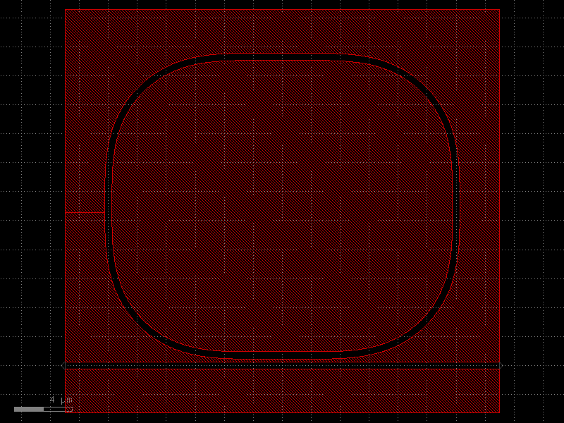
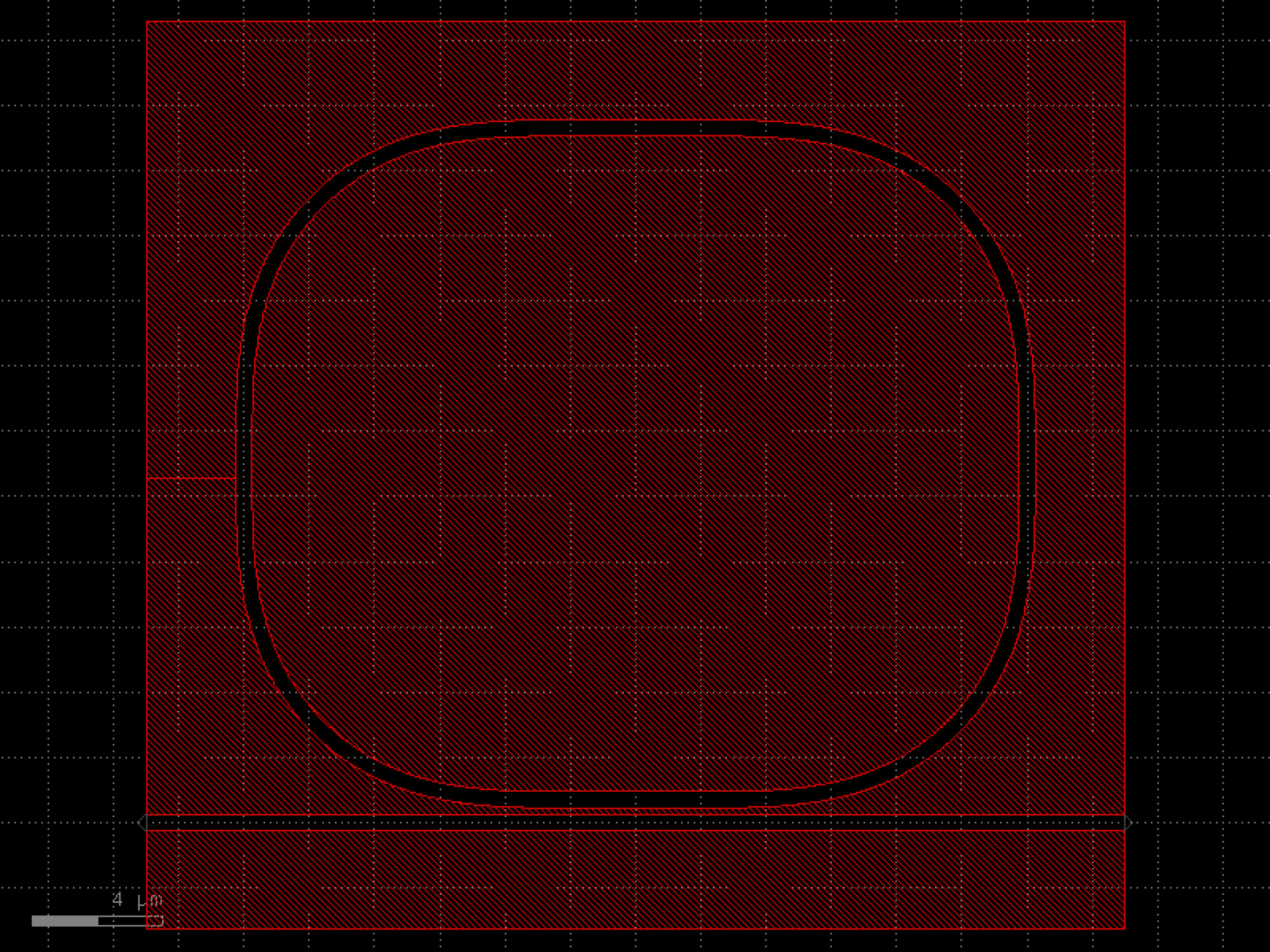

- gdsfactory.components.rings.ring_single_heater(gap=0.2, gap_top=None, gap_bot=None, radius=None, length_x=1.0, length_y=0.01, coupler_ring='coupler_ring', coupler_ring_top=None, straight='straight', bend='bend_euler', cross_section_heater='heater_metal', cross_section_waveguide_heater='strip_heater_metal', cross_section='strip', via_stack='via_stack_heater_mtop_mini', port_orientation=None, via_stack_offset=(1, 0), via_stack_size=None, *, with_drop=False, length_extension=None, length_extension_top=None, length_extension_bot=None)#
Returns a double bus ring with heater on top.
two couplers (ct: top, cb: bottom) connected with two vertical straights (sl: left, sr: right)
- Parameters:
gap (float) – gap between for coupler.
gap_top (float | None) – gap for the top coupler. Defaults to gap.
gap_bot (float | None) – gap for the bottom coupler. Defaults to gap.
radius (float | None) – for the bend and coupler.
length_x (float) – ring coupler length.
length_y (float) – vertical straight length.
coupler_ring (ComponentSpec) – ring coupler spec.
coupler_ring_top (ComponentSpec | None) – ring coupler spec for coupler away from vias (defaults to coupler_ring)
straight (ComponentSpec) – straight spec.
bend (ComponentSpec) – bend spec.
cross_section_heater (CrossSectionSpec) – for heater.
cross_section_waveguide_heater (CrossSectionSpec) – for waveguide with heater.
cross_section (CrossSectionSpec) – for regular waveguide.
via_stack (ComponentSpec) – for heater to routing metal.
port_orientation (AngleInDegrees | None) – for electrical ports to promote from via_stack.
via_stack_size (Float2 | None) – size of via_stack.
via_stack_offset (Float2) – x,y offset for via_stack.
with_drop (bool) – adds drop ports.
length_extension (float | None) – straight length extension at the end of the coupler bottom ports.
length_extension_top (float | None) – straight length extension at the end of the coupler top ports.
length_extension_bot (float | None) – straight length extension at the end of the coupler bottom ports.
- Return type:
o2──────▲─────────o3 │gap_top xx──────▼─────────xxx xxx xxx xxx xxx xx xxx x xxx xx xx▲ xx xx│length_y xx xx▼ xx xx xx length_x x xx ◄───────────────► x xx xxx xx xxx xxx──────▲─────────xxx │gap o1──────▼─────────o4
import gdsfactory as gf
gf.gpdk.PDK.activate()
c = gf.components.ring_single_heater(gap=0.2, length_x=1, length_y=0.01, coupler_ring='coupler_ring', straight='straight', bend='bend_euler', cross_section_heater='heater_metal', cross_section_waveguide_heater='strip_heater_metal', cross_section='strip', via_stack='via_stack_heater_mtop_mini', via_stack_offset=(1, 0), with_drop=False).copy()
c.draw_ports()
c.plot()
(Source code, png, hires.png, pdf)
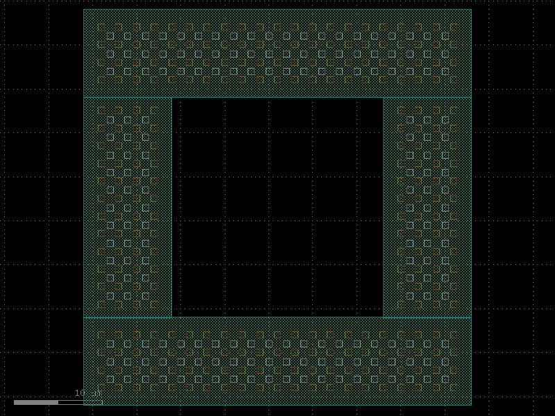
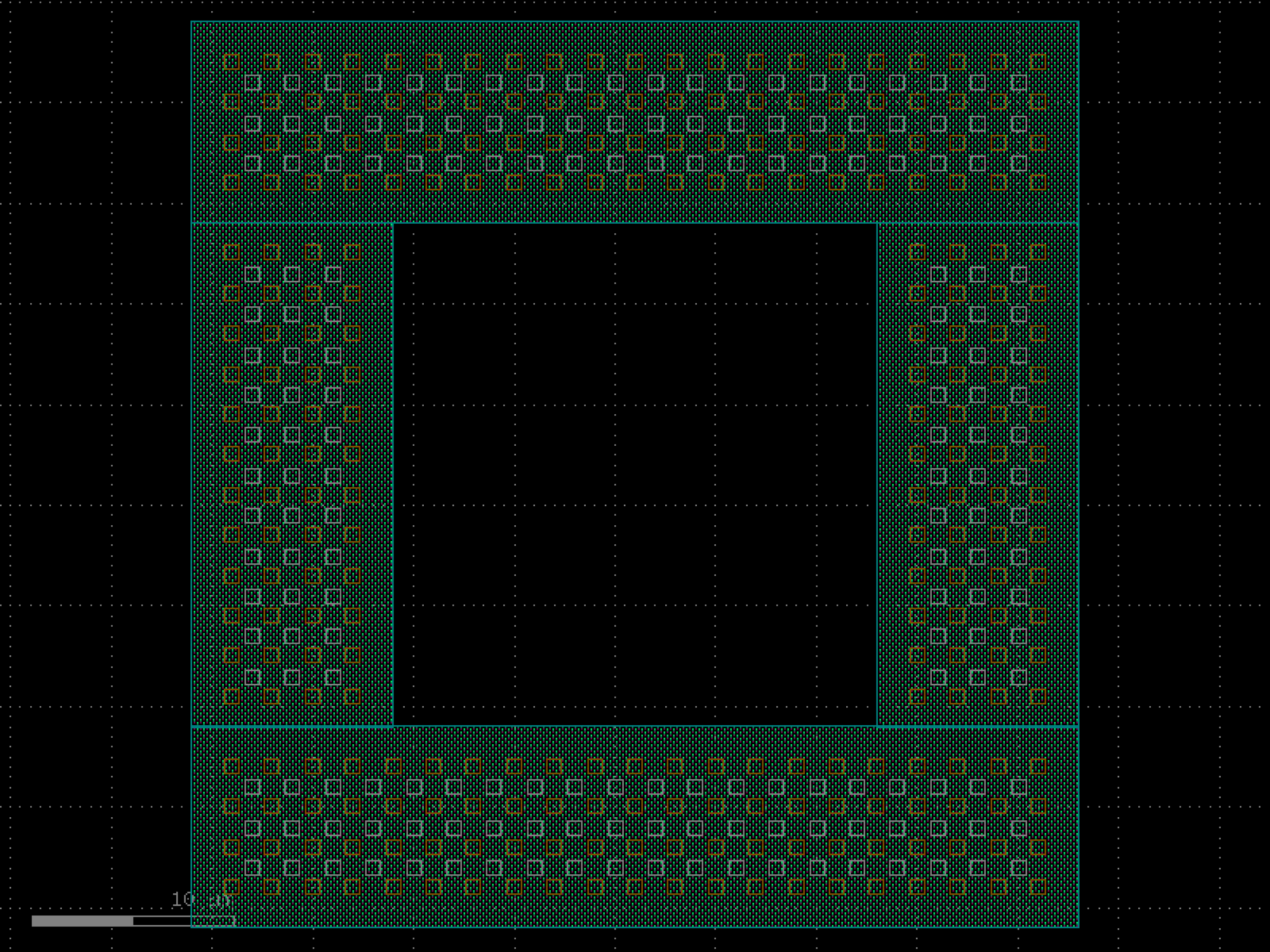

- gdsfactory.components.rings.ring_single_pn(gap=0.3, radius=5.0, doping_angle=250, cross_section=<function rib>, pn_cross_section=functools.partial(<function pn>, width_doping=2.425, width_slab=4.85, layer_via='VIAC', width_via=0.5, layer_metal='M1', width_metal=0.5), doped_heater=True, doped_heater_angle_buffer=10, doped_heater_layer='NPP', doped_heater_width=0.5, doped_heater_waveguide_offset=1.175, heater_vias=functools.partial(<function via_stack>, size=(0.5, 0.5), layers=('M1', 'M2', 'M3'), vias=(functools.partial(<function via>, layer='VIAC', size=(0.1, 0.1), enclosure=0.01, pitch=0.2), functools.partial(<function via>, layer='VIA1', size=(0.1, 0.1), enclosure=0.01, pitch=0.2), None), correct_size=True), pn_vias='via_stack_slab_m3', pn_vias_width=3)[source]#
Returns single pn ring with optional doped heater.
- Parameters:
gap (float) – gap between for coupler.
radius (float) – for the bend and coupler.
doping_angle (float) – angle in degrees representing portion of ring that is doped.
length_x – ring coupler length.
length_y – vertical straight length.
cross_section (CrossSectionSpec) – cross_section spec for non-PN doped rib waveguide sections.
pn_cross_section (CrossSectionSpec) – cross section of pn junction.
doped_heater (bool) – boolean for if we include doped heater or not.
doped_heater_angle_buffer (float) – angle in degrees buffering heater from pn junction.
doped_heater_layer (LayerSpec) – doping layer for heater.
doped_heater_width (float) – width of doped heater.
doped_heater_waveguide_offset (float) – distance from the center of the ring waveguide to the center of the doped heater.
heater_vias (ComponentSpec) – components specifications for heater vias.
pn_vias (ComponentSpec) – components specifications for pn vias.
pn_vias_width (float) – width of pn vias.
- Return type:
import gdsfactory as gf
gf.gpdk.PDK.activate()
c = gf.components.ring_single_pn(gap=0.3, radius=5, doping_angle=250, doped_heater=True, doped_heater_angle_buffer=10, doped_heater_layer='NPP', doped_heater_width=0.5, doped_heater_waveguide_offset=1.175, pn_vias='via_stack_slab_m3', pn_vias_width=3).copy()
c.draw_ports()
c.plot()
(Source code, png, hires.png, pdf)
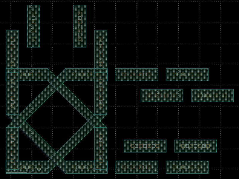
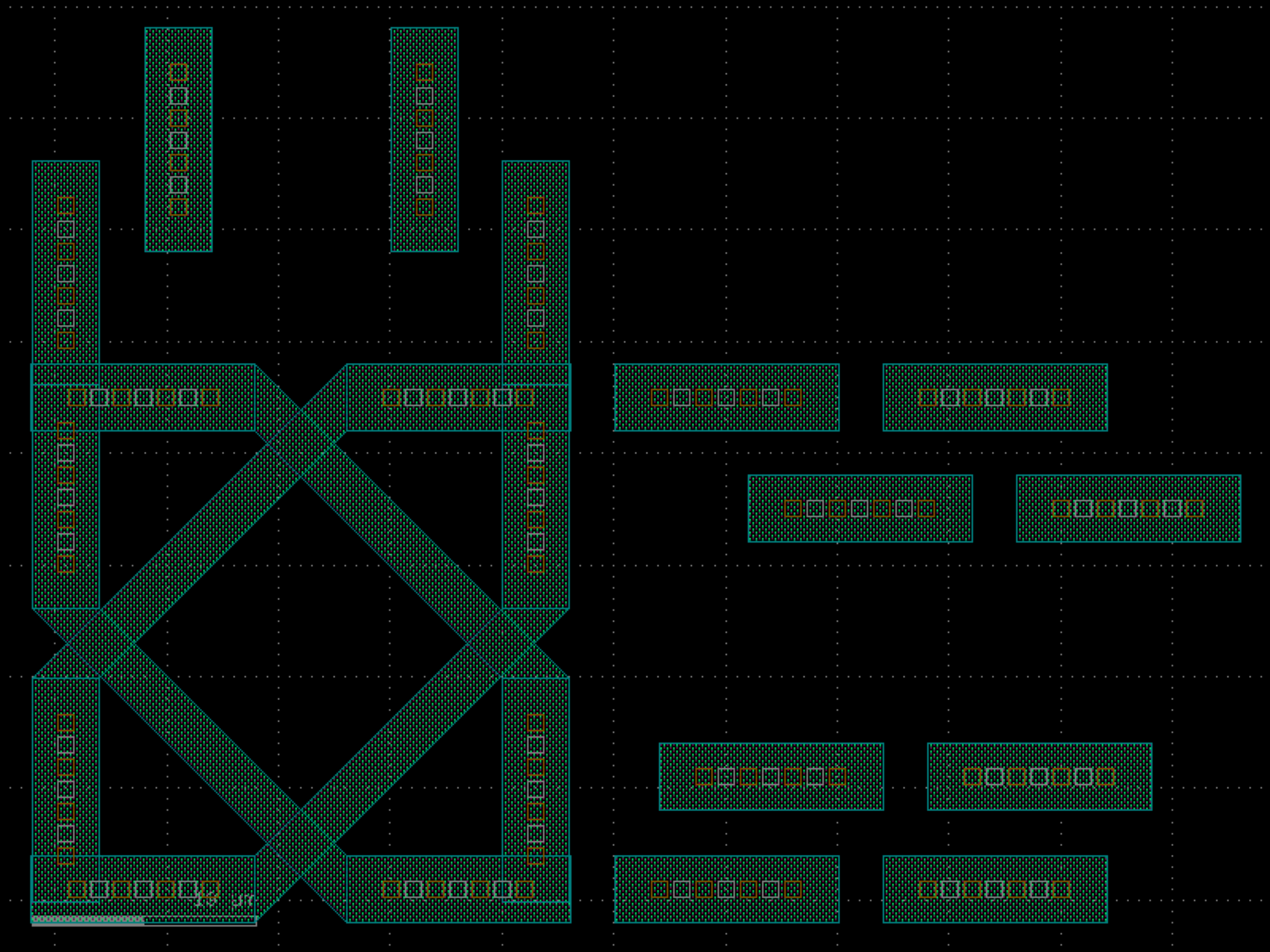

shapes#
- gdsfactory.components.shapes.C(width=1.0, size=(10.0, 20.0), layer='WG', port_type='electrical')[source]#
C geometry with ports on both ends.
based on phidl.
- Parameters:
width (float) – of the line.
size (tuple[float, float]) – length and height of the base.
layer (LayerSpec) – layer spec.
port_type (str) – optical or electrical.
- Return type:
______ | o1 | ___ | | | |___ ||<---> size[0] |______ o2
import gdsfactory as gf
gf.gpdk.PDK.activate()
c = gf.components.C(width=1, size=(10, 20), layer='WG', port_type='electrical').copy()
c.draw_ports()
c.plot()
(Source code, png, hires.png, pdf)
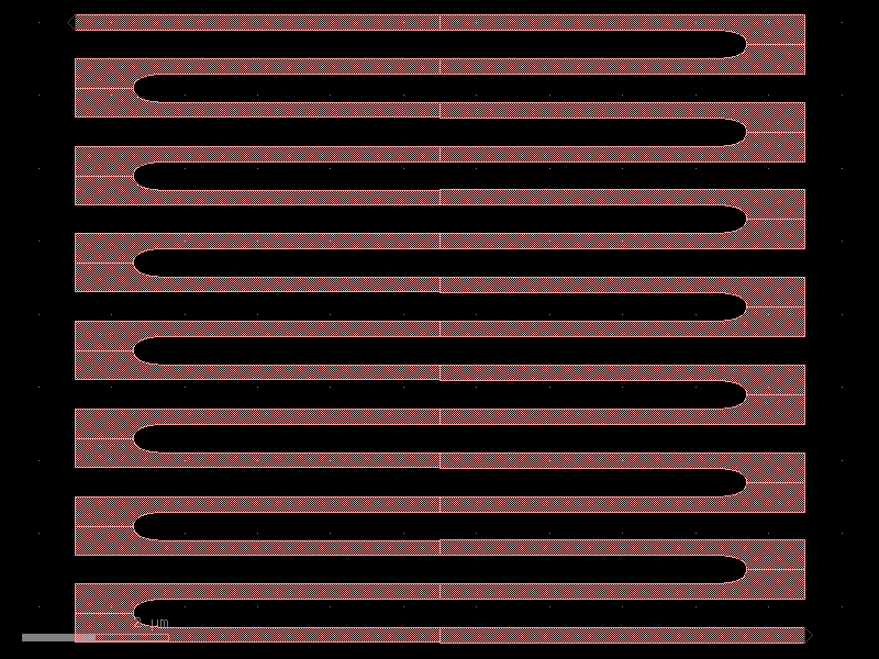
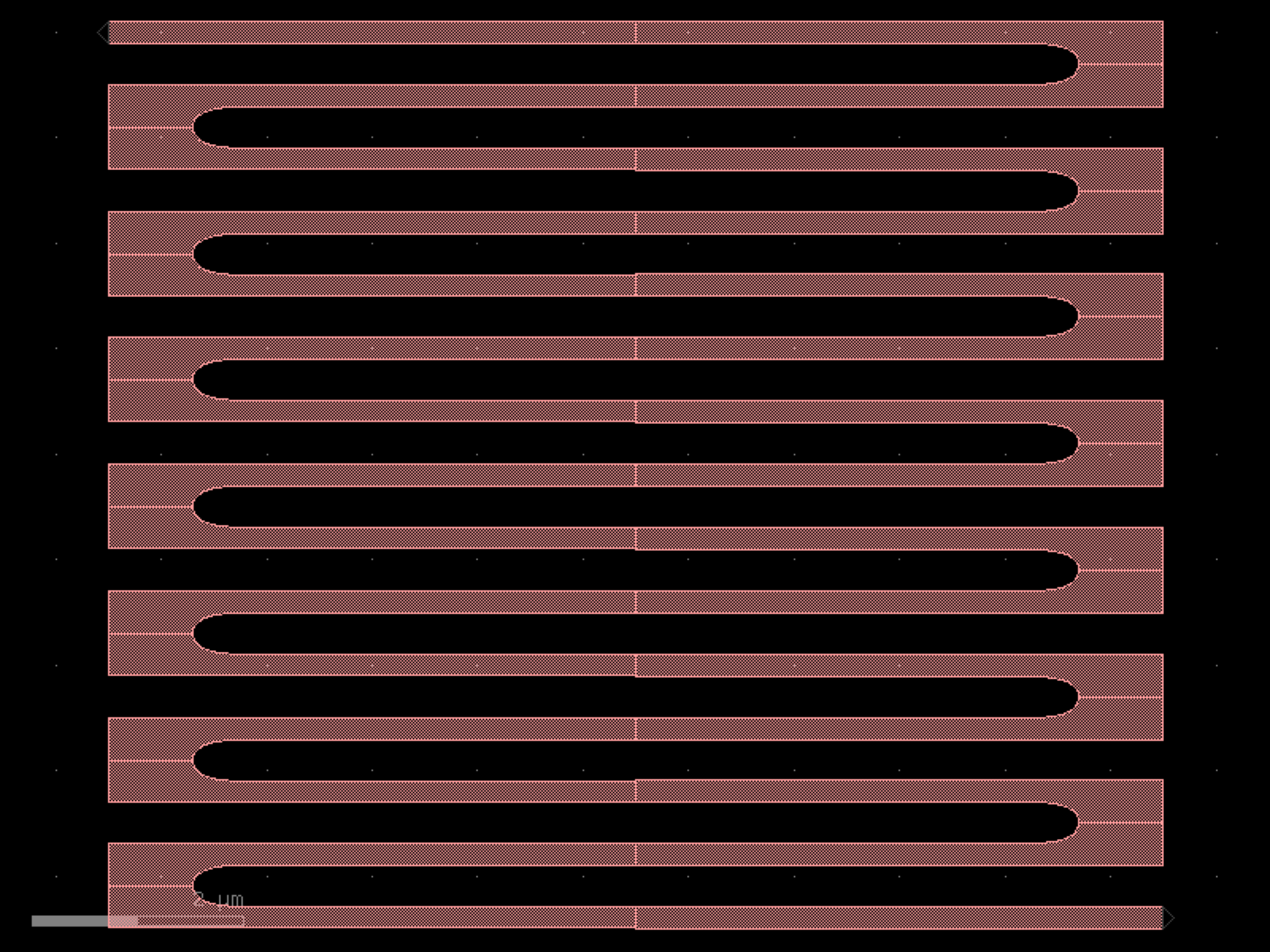

- gdsfactory.components.shapes.L(width=1, size=(10, 20), layer='MTOP', port_type='electrical')[source]#
Generates an ‘L’ geometry with ports on both ends.
Based on phidl.
- Parameters:
width (int | float) – of the line.
size (tuple[int, int]) – length and height of the base.
layer (LayerSpec) – spec.
port_type (str) – for port.
- Return type:
import gdsfactory as gf
gf.gpdk.PDK.activate()
c = gf.components.L(width=1, size=(10, 20), layer='MTOP', port_type='electrical').copy()
c.draw_ports()
c.plot()
(Source code, png, hires.png, pdf)
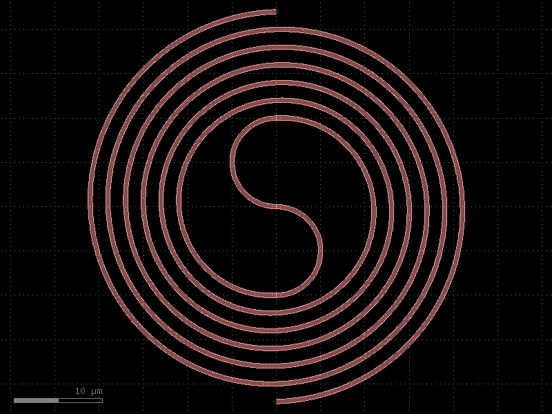
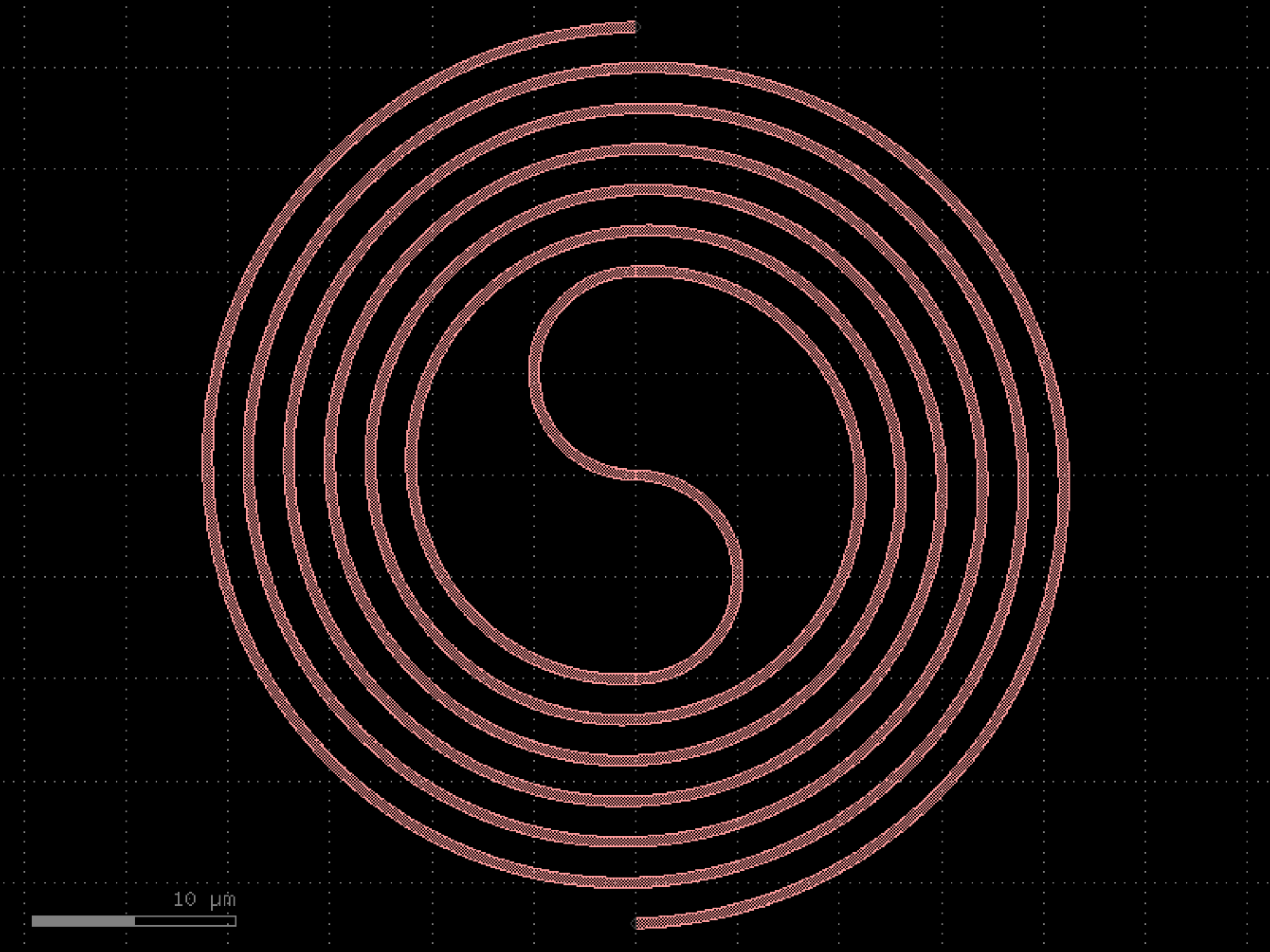

- gdsfactory.components.shapes.circle(radius=10.0, angle_resolution=2.5, layer='WG')[source]#
Generate a circle geometry.
- Parameters:
radius (float) – of the circle.
angle_resolution (float) – number of degrees per point.
layer (LayerSpec) – layer.
- Return type:
import gdsfactory as gf
gf.gpdk.PDK.activate()
c = gf.components.circle(radius=10, angle_resolution=2.5, layer='WG').copy()
c.draw_ports()
c.plot()
(Source code, png, hires.png, pdf)
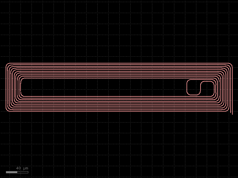
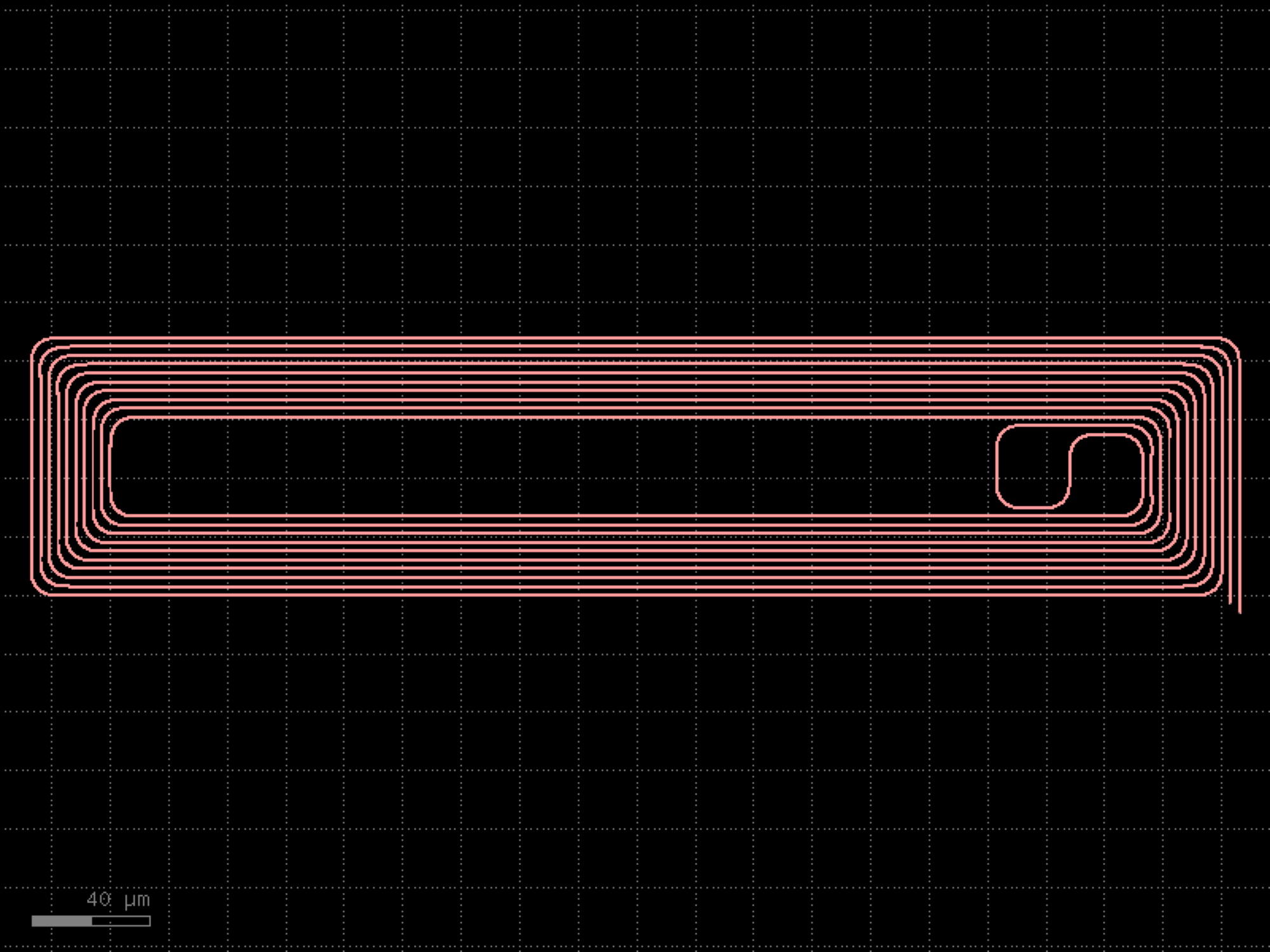

- gdsfactory.components.shapes.circle_wave(radius=10.0, amplitude=1.0, n_oscillations=8, angle_resolution=1.0, layer='WG')[source]#
Returns a circle with a sinusoidal boundary variation.
The boundary radius varies as r(theta) = radius + amplitude * sin(n * theta).
- Parameters:
radius (float) – mean radius.
amplitude (float) – amplitude of sinusoidal modulation.
n_oscillations (int) – number of oscillations around the boundary.
angle_resolution (float) – degrees per point.
layer (LayerSpec) – layer spec.
- Return type:
import gdsfactory as gf
gf.gpdk.PDK.activate()
c = gf.components.circle_wave(radius=10, amplitude=1, n_oscillations=8, angle_resolution=1, layer='WG').copy()
c.draw_ports()
c.plot()
(Source code, png, hires.png, pdf)
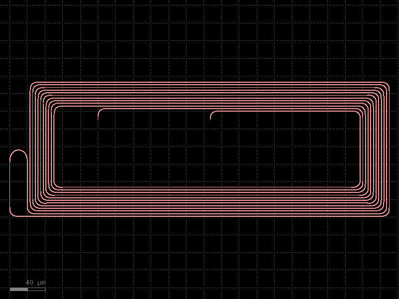
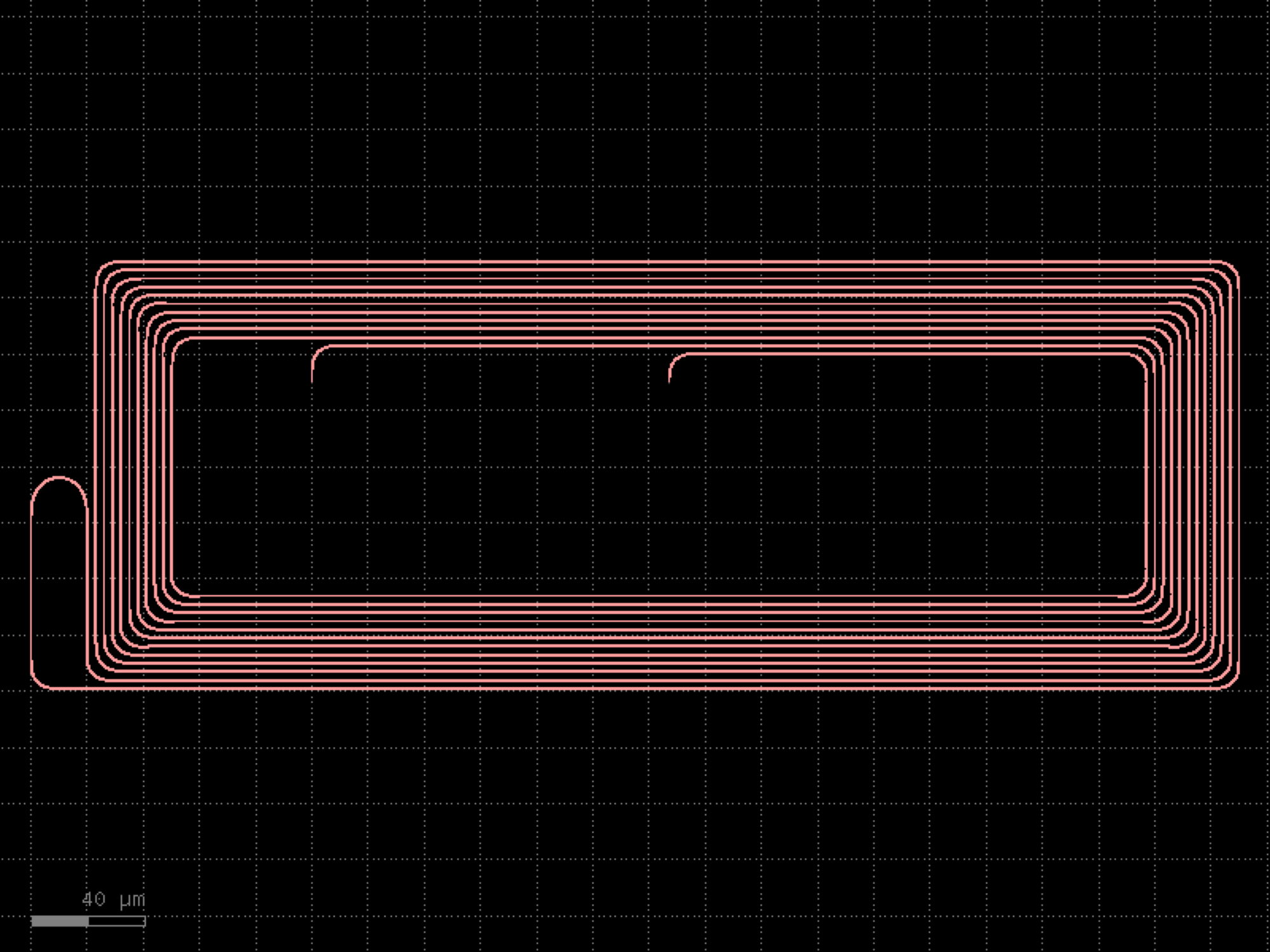

- gdsfactory.components.shapes.compass(size=(4.0, 2.0), layer='WG', port_type='electrical', port_inclusion=0.0, port_orientations=(180, 90, 0, -90), auto_rename_ports=True)[source]#
Rectangle with ports on each edge (north, south, east, and west).
- Parameters:
size (tuple[float, float]) – rectangle size.
layer (LayerSpec) – tuple (int, int).
port_type (str | None) – optical, electrical.
port_inclusion (float) – from edge.
port_orientations (tuple[int, ...] | list[int] | None) – list of port_orientations to add. None does not add ports.
auto_rename_ports (bool) – auto rename ports.
- Return type:
import gdsfactory as gf
gf.gpdk.PDK.activate()
c = gf.components.compass(size=(4, 2), layer='WG', port_type='electrical', port_inclusion=0, port_orientations=(180, 90, 0, -90), auto_rename_ports=True).copy()
c.draw_ports()
c.plot()
(Source code, png, hires.png, pdf)

- gdsfactory.components.shapes.cross(length=10.0, width=3.0, layer='WG', port_type=None)[source]#
Returns a cross from two rectangles of length and width.
- Parameters:
length (float) – float Length of the cross from one end to the other.
width (float) – float Width of the arms of the cross.
layer (LayerSpec) – layer for geometry.
port_type (str | None) – None, optical, electrical.
- Return type:
import gdsfactory as gf
gf.gpdk.PDK.activate()
c = gf.components.cross(length=10, width=3, layer='WG').copy()
c.draw_ports()
c.plot()
(Source code, png, hires.png, pdf)
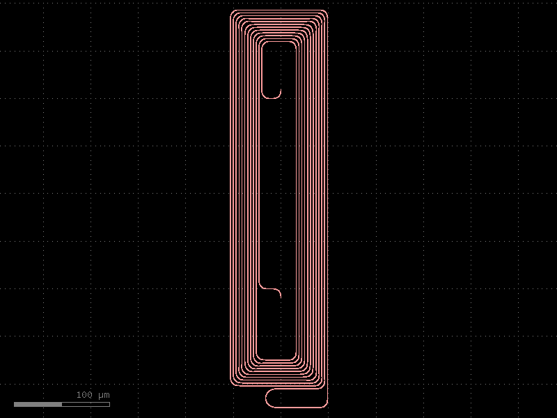
- gdsfactory.components.shapes.dash(width=10.0, width_end=1.0, length=20.0, taper_length=5.0, tip_length=2.0, n_bezier_points=30, layer='WG')[source]#
Returns a dash shape with Bezier-curved tapered tips.
An elongated shape wider in the middle (width) that tapers via Bezier curves to a narrower tip (width_end) at each end. Based on the pyNISTtoolbox Dash pattern.
- Parameters:
width (float) – width at the center/body of the dash.
width_end (float) – width at the tips.
length (float) – total length of the straight body section.
taper_length (float) – length of each tapered transition.
tip_length (float) – length of each rounded tip beyond the taper.
n_bezier_points (int) – points per Bezier curve segment.
layer (LayerSpec) – layer spec.
- Return type:
import gdsfactory as gf
gf.gpdk.PDK.activate()
c = gf.components.dash(width=10, width_end=1, length=20, taper_length=5, tip_length=2, n_bezier_points=30, layer='WG').copy()
c.draw_ports()
c.plot()
(Source code, png, hires.png, pdf)
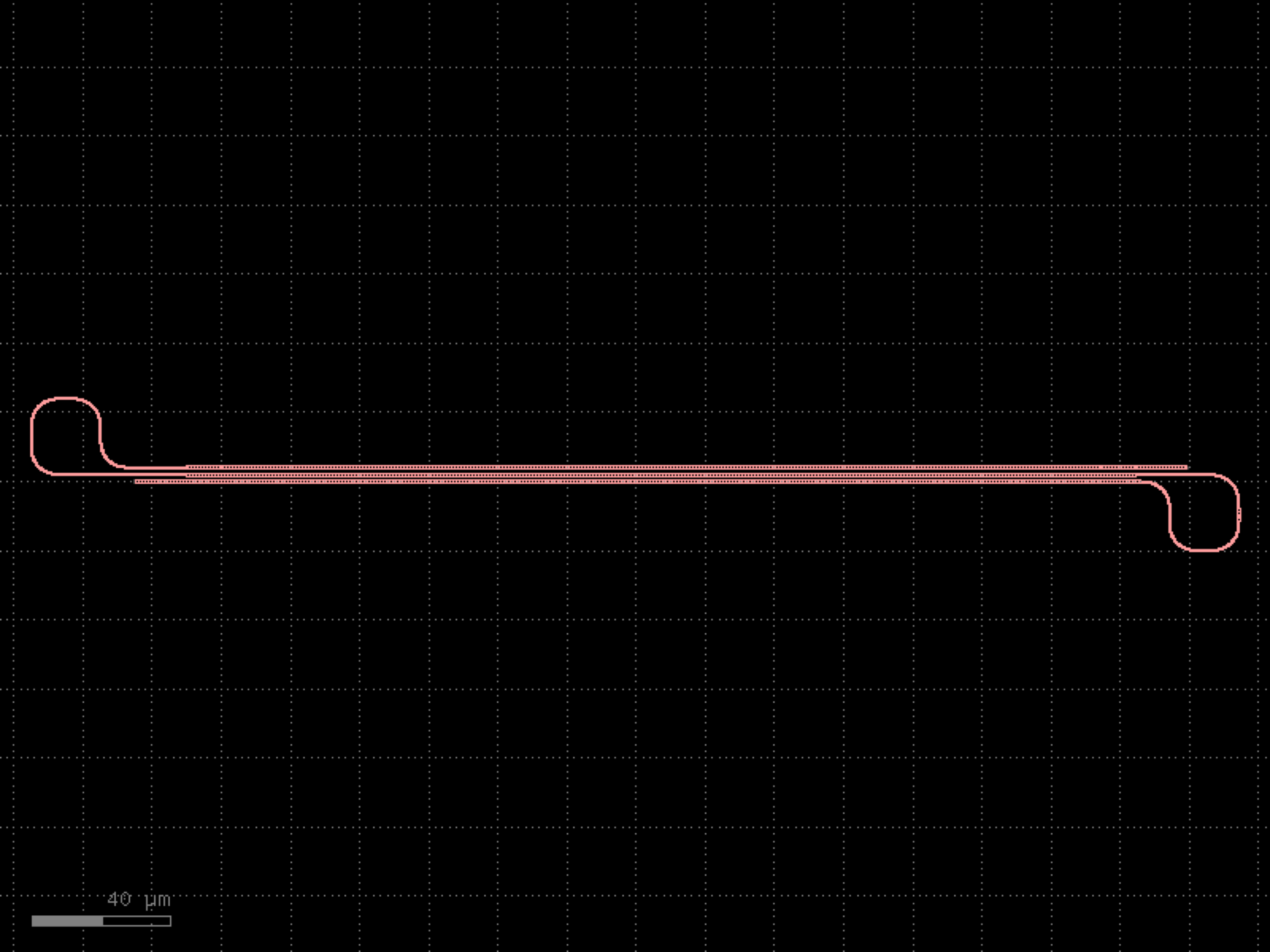

- gdsfactory.components.shapes.ellipse(radii=(10.0, 5.0), angle_resolution=2.5, layer='WG')[source]#
Returns ellipse component.
- Parameters:
radii (tuple[float, float]) – Semimajor and semiminor axis lengths of the ellipse.
angle_resolution (float) – number of degrees per point.
layer (LayerSpec) – Specific layer(s) to put polygon geometry on.
- Return type:
The orientation of the ellipse is determined by the order of the radii variables; if the first element is larger, the ellipse will be horizontal and if the second element is larger, the ellipse will be vertical.
import gdsfactory as gf
gf.gpdk.PDK.activate()
c = gf.components.ellipse(radii=(10, 5), angle_resolution=2.5, layer='WG').copy()
c.draw_ports()
c.plot()
(Source code, png, hires.png, pdf)
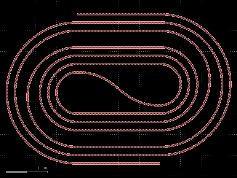
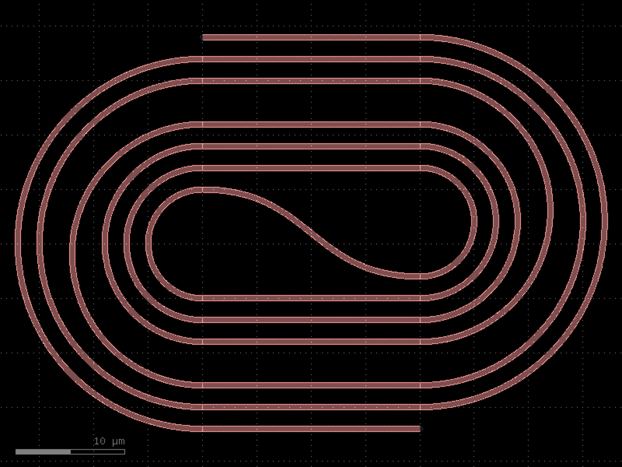

- gdsfactory.components.shapes.fiducial_squares(layers=('WG',), size=(5, 5), offset=0.14)[source]#
Returns fiducials with two squares.
- Parameters:
layers (LayerSpecs) – list of layers to draw the squares.
size (tuple[float, float]) – size of each square in um.
offset (float) – space between squares in x and y.
- Return type:
import gdsfactory as gf
gf.gpdk.PDK.activate()
c = gf.components.fiducial_squares(layers=('WG',), size=(5, 5), offset=0.14).copy()
c.draw_ports()
c.plot()
(Source code, png, hires.png, pdf)
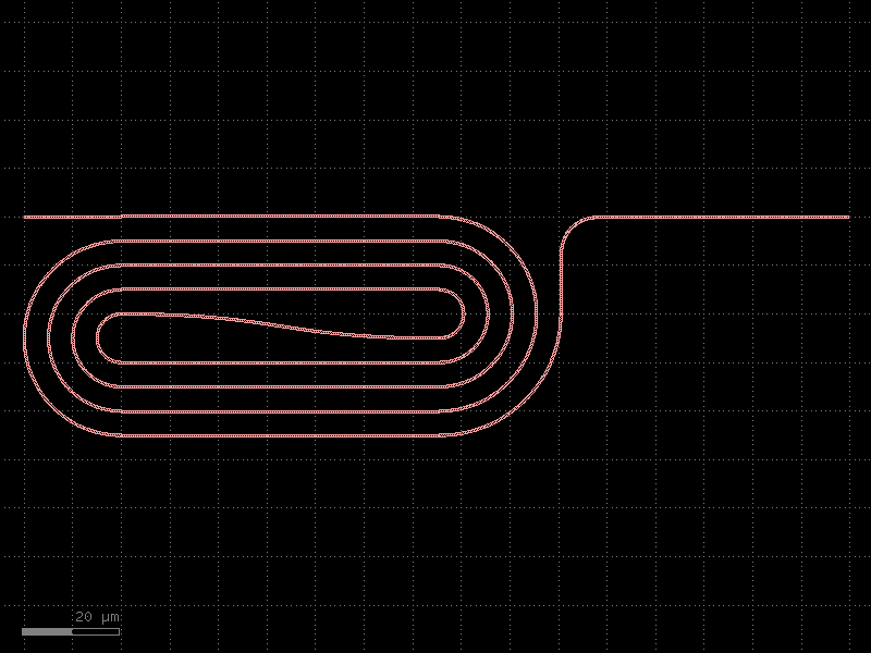
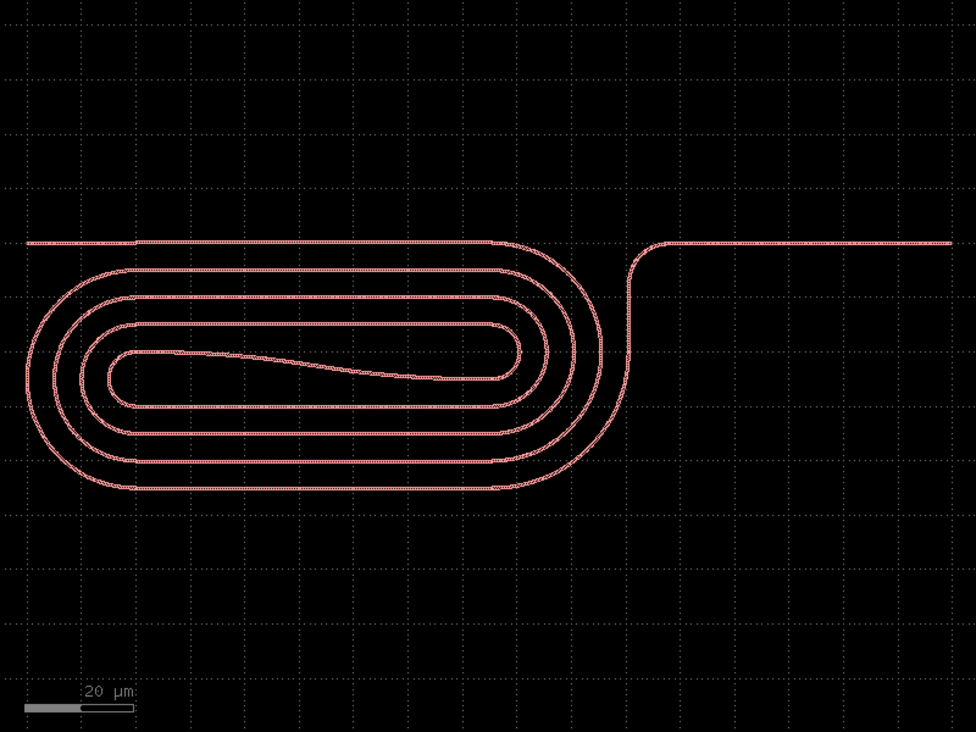

- gdsfactory.components.shapes.fractal(fractal_type='sierpinski_triangle', depth=4, size=100.0, layer='WG')[source]#
Returns a fractal pattern.
- Parameters:
fractal_type (Literal['sierpinski_triangle', 'sierpinski_carpet', 'vicsek_cross', 'vicsek_saltire']) – type of fractal.
depth (int) – recursion depth (max recommended: 6).
size (float) – overall size of the fractal.
layer (LayerSpec) – layer spec.
- Return type:
import gdsfactory as gf
gf.gpdk.PDK.activate()
c = gf.components.fractal(fractal_type='sierpinski_triangle', depth=4, size=100, layer='WG').copy()
c.draw_ports()
c.plot()
(Source code, png, hires.png, pdf)
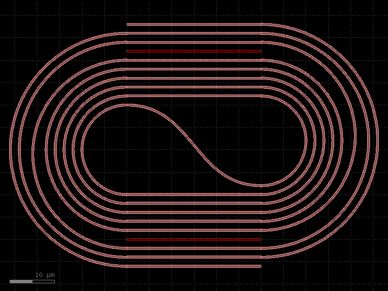
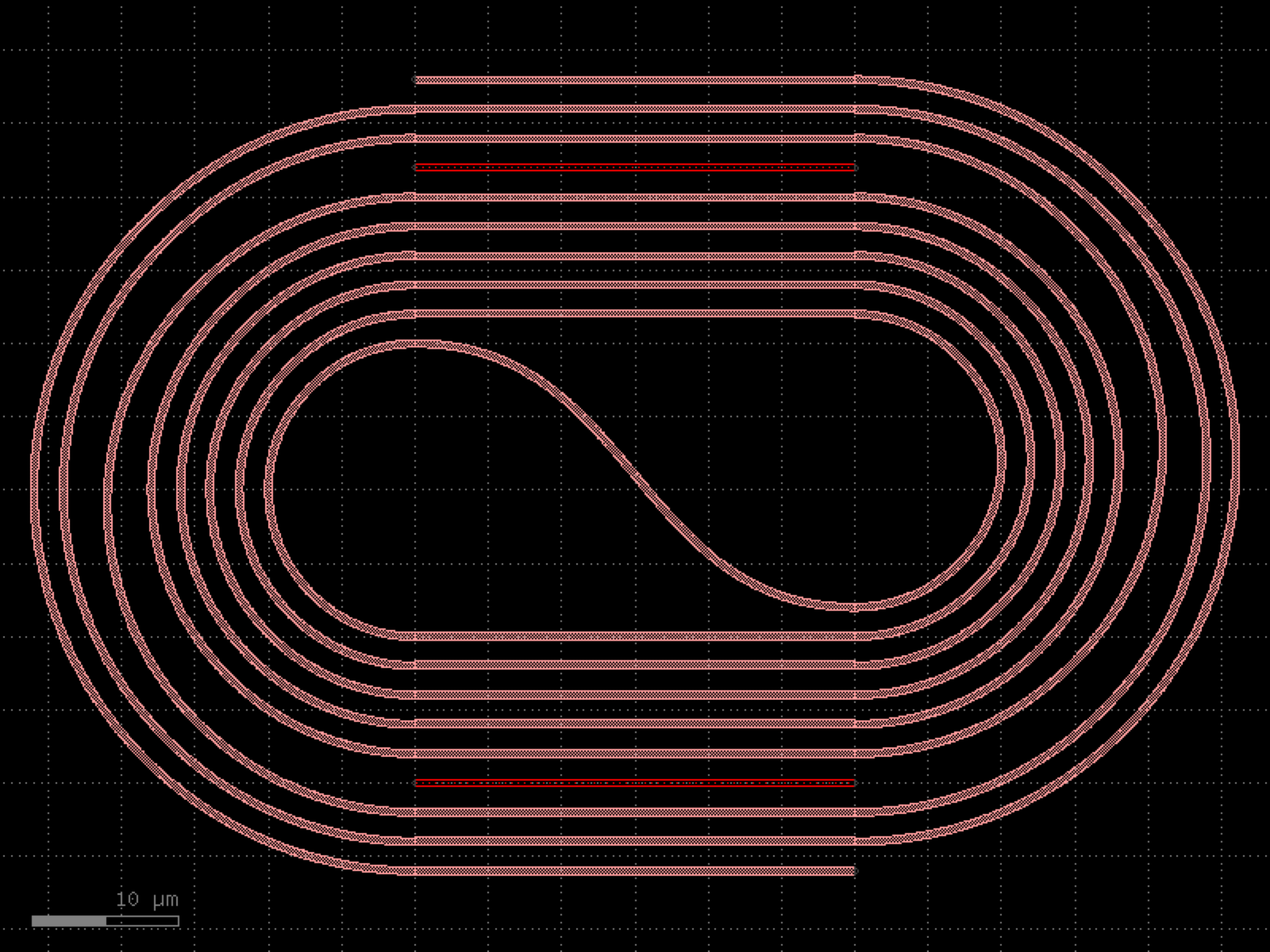

- gdsfactory.components.shapes.hexagon(*, sides=6, side_length=10, layer='WG', port_width=None, port_type='placement')#
Returns a regular N-sided polygon, with ports on each edge.
- Parameters:
sides (int) – number of sides for the polygon.
side_length (float) – of the edges.
layer (LayerSpec) – Specific layer to put polygon geometry on.
port_width (float | None) – the width of port of the polygon (in electrical pads, the port width may not equal to the side length).
port_type (str | None) – optical, electrical.
- Return type:
import gdsfactory as gf
gf.gpdk.PDK.activate()
c = gf.components.hexagon(sides=6, side_length=10, layer='WG', port_type='placement').copy()
c.draw_ports()
c.plot()
(Source code, png, hires.png, pdf)
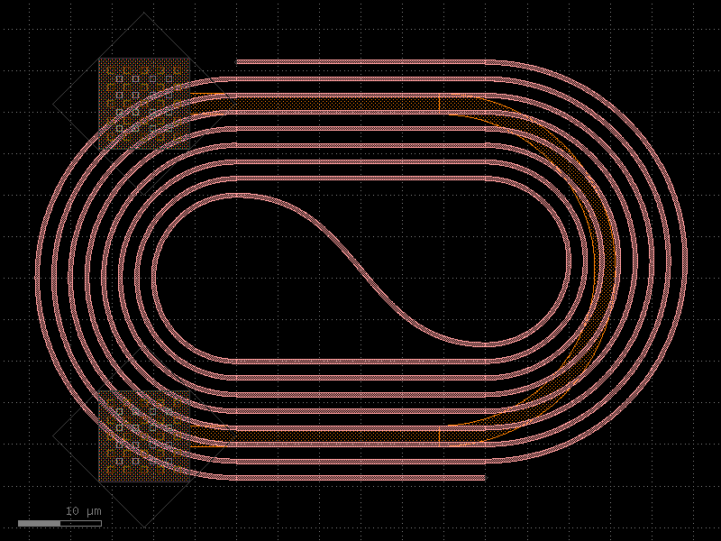
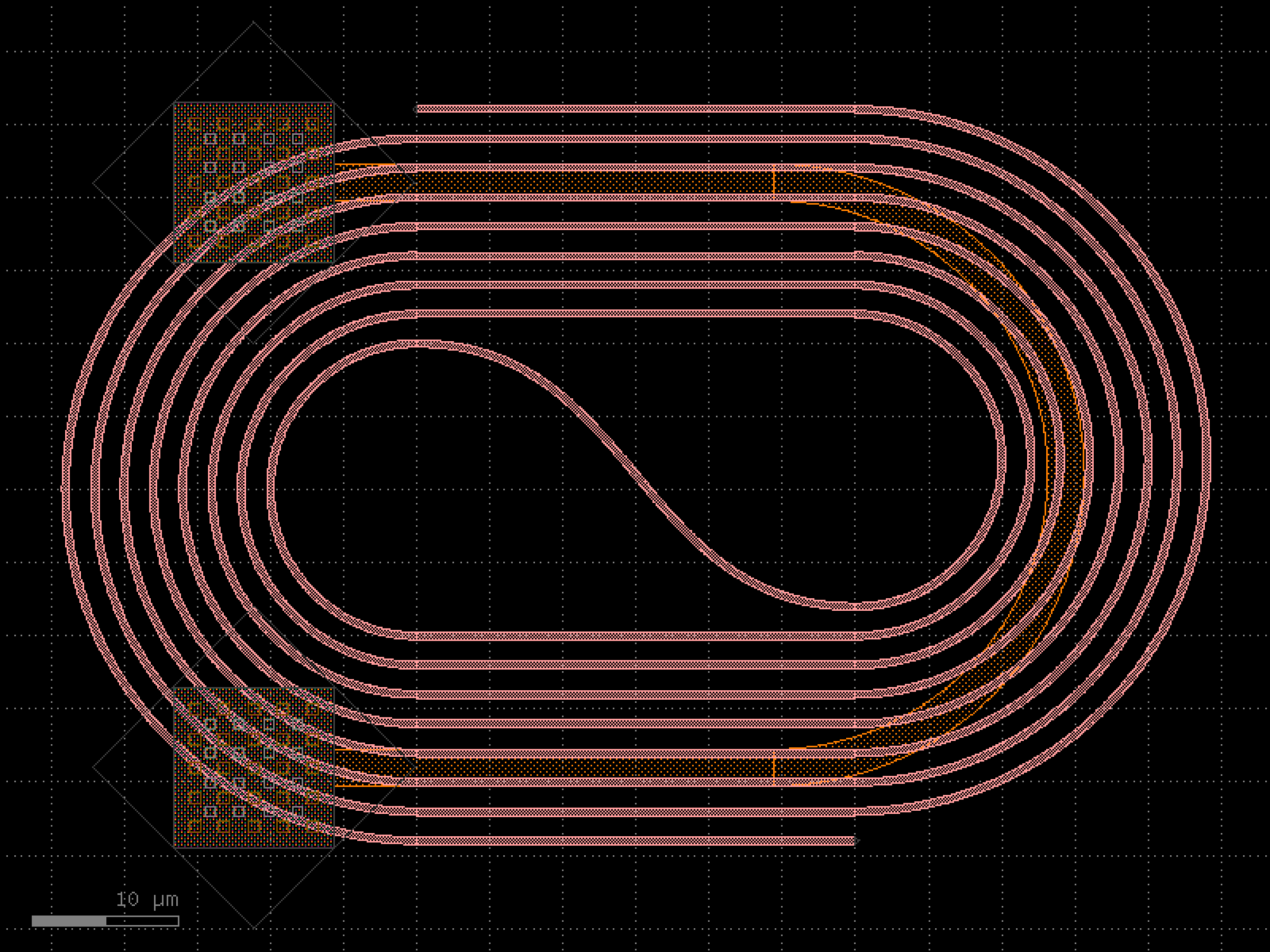

- gdsfactory.components.shapes.marker_te(*, size=(10.4, 10.4), layer='TE', centered=True, port_type='electrical', port_orientations=(180, 90, 0, -90))#
Returns a rectangle.
- Parameters:
size (Size) – (tuple) Width and height of rectangle.
layer (LayerSpec) – Specific layer to put polygon geometry on.
centered (bool) – True sets center to (0, 0), False sets south-west to (0, 0).
port_type (str | None) – optical, electrical.
port_orientations (Ints | None) – list of port_orientations to add. None adds no ports.
- Return type:
import gdsfactory as gf
gf.gpdk.PDK.activate()
c = gf.components.marker_te(size=(10.4, 10.4), layer='TE', centered=True, port_type='electrical', port_orientations=(180, 90, 0, -90)).copy()
c.draw_ports()
c.plot()
(Source code, png, hires.png, pdf)
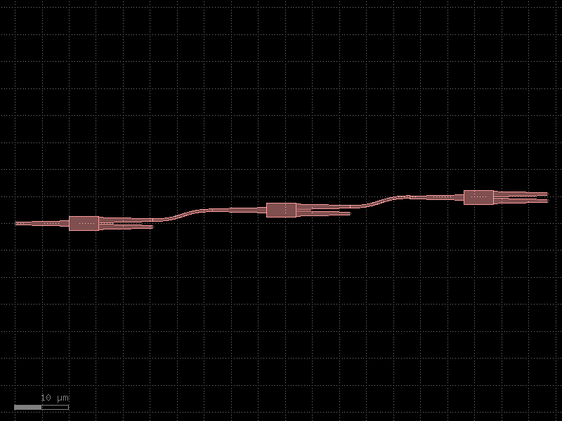
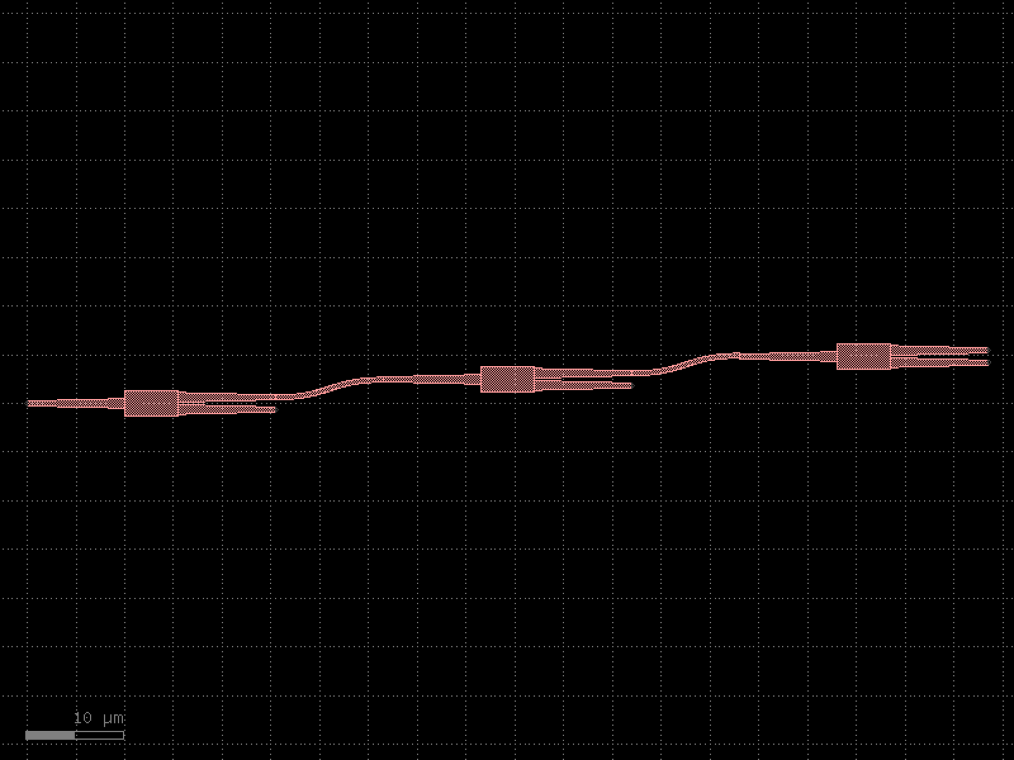

- gdsfactory.components.shapes.marker_tm(*, size=(10.4, 10.4), layer='TM', centered=True, port_type='electrical', port_orientations=(180, 90, 0, -90))#
Returns a rectangle.
- Parameters:
size (Size) – (tuple) Width and height of rectangle.
layer (LayerSpec) – Specific layer to put polygon geometry on.
centered (bool) – True sets center to (0, 0), False sets south-west to (0, 0).
port_type (str | None) – optical, electrical.
port_orientations (Ints | None) – list of port_orientations to add. None adds no ports.
- Return type:
import gdsfactory as gf
gf.gpdk.PDK.activate()
c = gf.components.marker_tm(size=(10.4, 10.4), layer='TM', centered=True, port_type='electrical', port_orientations=(180, 90, 0, -90)).copy()
c.draw_ports()
c.plot()
(Source code, png, hires.png, pdf)
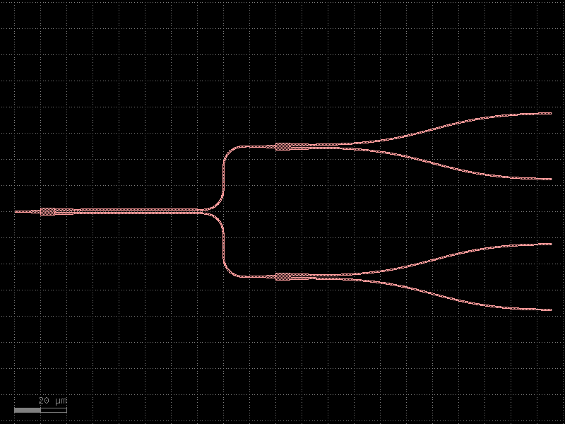
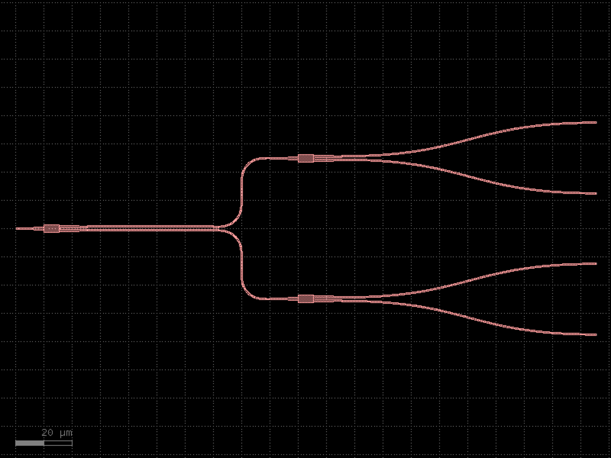

- gdsfactory.components.shapes.nxn(west=1, east=4, north=0, south=0, xsize=8.0, ysize=8.0, wg_width=0.5, layer='WG', wg_margin=1.0, **kwargs)[source]#
Returns a nxn component with nxn ports (west, east, north, south).
- Parameters:
west (int) – number of west ports.
east (int) – number of east ports.
north (int) – number of north ports.
south (int) – number of south ports.
xsize (float) – size in X.
ysize (float) – size in Y.
wg_width (float) – width of the straight ports.
layer (LayerSpec) – layer.
wg_margin (float) – margin from straight to component edge.
kwargs (Any) – port_settings.
- Return type:
3 4 |___|_ 2 -| |- 5 | | 1 -|______|- 6 | | 8 7
import gdsfactory as gf
gf.gpdk.PDK.activate()
c = gf.components.nxn(west=1, east=4, north=0, south=0, xsize=8, ysize=8, wg_width=0.5, layer='WG', wg_margin=1).copy()
c.draw_ports()
c.plot()
(Source code, png, hires.png, pdf)
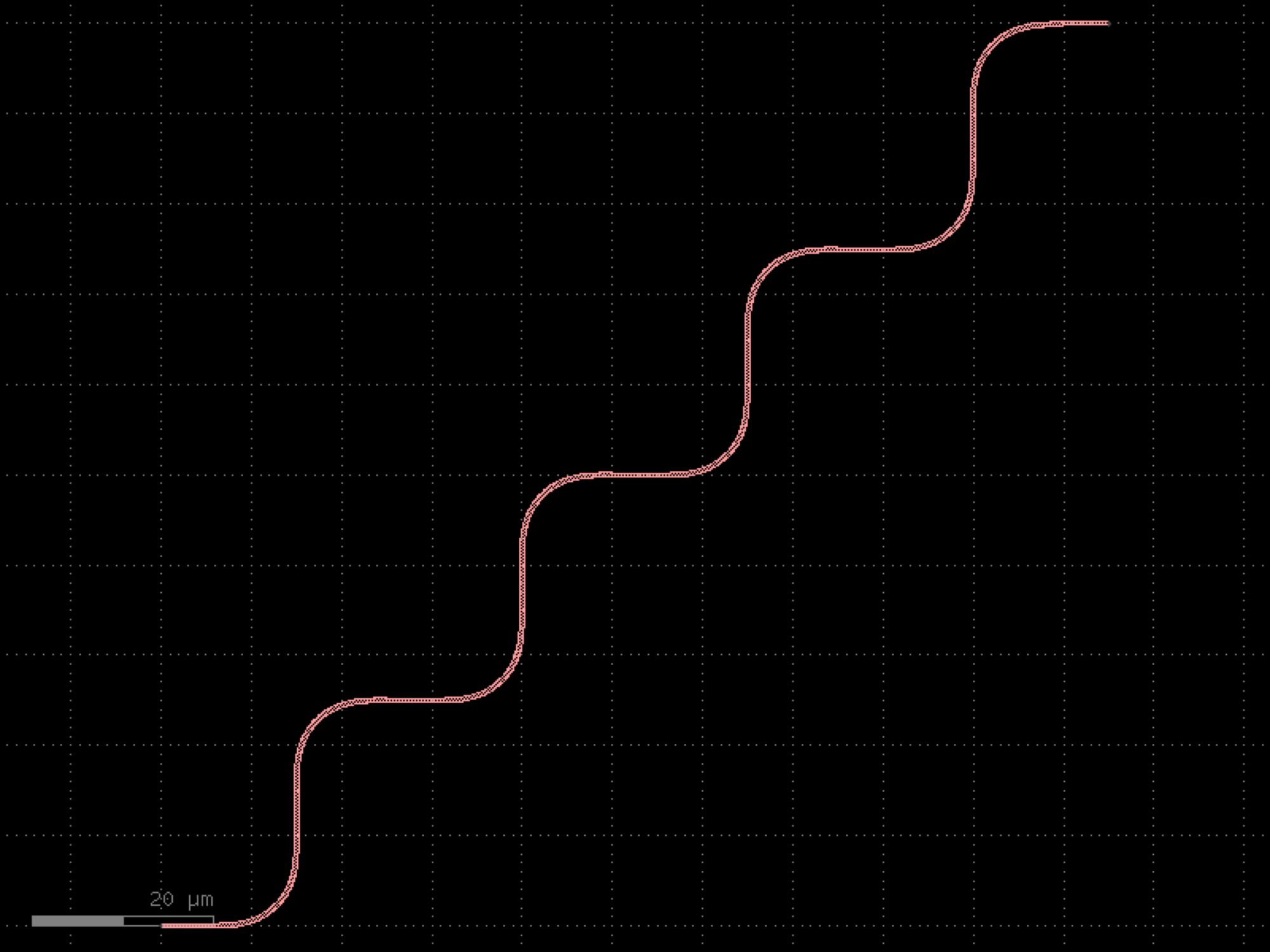
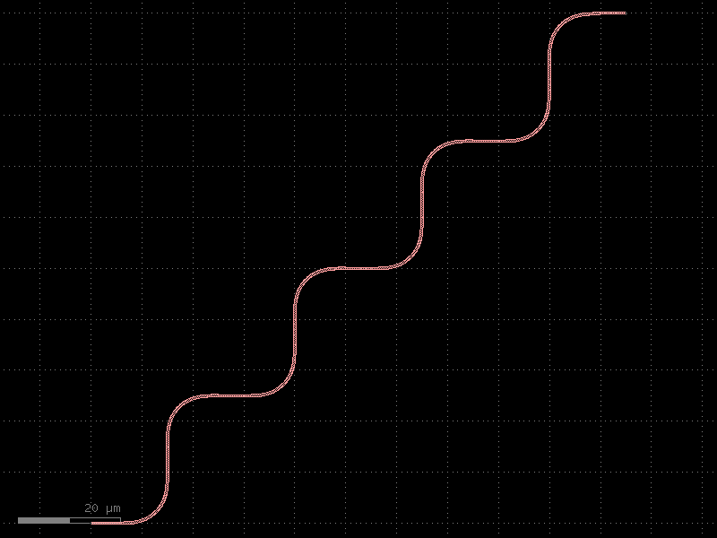
- gdsfactory.components.shapes.octagon(*, sides=8, side_length=10, layer='WG', port_width=None, port_type='placement')#
Returns a regular N-sided polygon, with ports on each edge.
- Parameters:
sides (int) – number of sides for the polygon.
side_length (float) – of the edges.
layer (LayerSpec) – Specific layer to put polygon geometry on.
port_width (float | None) – the width of port of the polygon (in electrical pads, the port width may not equal to the side length).
port_type (str | None) – optical, electrical.
- Return type:
import gdsfactory as gf
gf.gpdk.PDK.activate()
c = gf.components.octagon(sides=8, side_length=10, layer='WG', port_type='placement').copy()
c.draw_ports()
c.plot()
(Source code, png, hires.png, pdf)
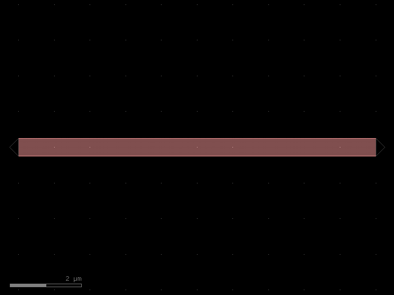
- gdsfactory.components.shapes.pie_arc(radius=10.0, radius_y=None, start_angle=0.0, end_angle=90.0, angle_resolution=2.5, layer='WG')[source]#
Returns a pie-shaped arc (sector/wedge), centered at origin.
The shape is a closed polygon from the origin along two radial lines connected by an elliptical arc.
- Parameters:
radius (float) – x-radius (or uniform radius if radius_y is None).
radius_y (float | None) – y-radius for elliptical arc. Defaults to radius.
start_angle (float) – start angle in degrees.
end_angle (float) – end angle in degrees.
angle_resolution (float) – degrees per arc point.
layer (LayerSpec) – layer spec.
- Return type:
import gdsfactory as gf
gf.gpdk.PDK.activate()
c = gf.components.pie_arc(radius=10, start_angle=0, end_angle=90, angle_resolution=2.5, layer='WG').copy()
c.draw_ports()
c.plot()
(Source code, png, hires.png, pdf)
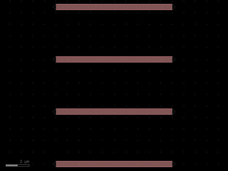
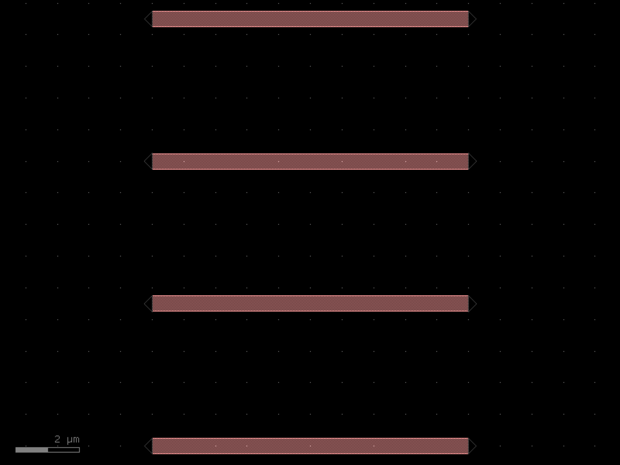

- gdsfactory.components.shapes.rect_su_shape(L1=10.0, L2=10.0, L3=20.0, width=1.0, layer='WG', port_type='electrical')[source]#
Returns a rectangular S- or U-shaped routing structure.
The shape consists of three connected rectangular segments forming an S or U pattern. Positive and negative values of L1, L2, L3 produce different orientations (S-shape, U-shape, etc.).
- Parameters:
L1 (float) – length of first vertical segment.
L2 (float) – length of horizontal segment.
L3 (float) – length of second vertical segment.
width (float) – width of all segments.
layer (LayerSpec) – layer spec.
port_type (str | None) – None, optical, or electrical.
- Return type:
import gdsfactory as gf
gf.gpdk.PDK.activate()
c = gf.components.rect_su_shape(L1=10, L2=10, L3=20, width=1, layer='WG', port_type='electrical').copy()
c.draw_ports()
c.plot()
(Source code, png, hires.png, pdf)
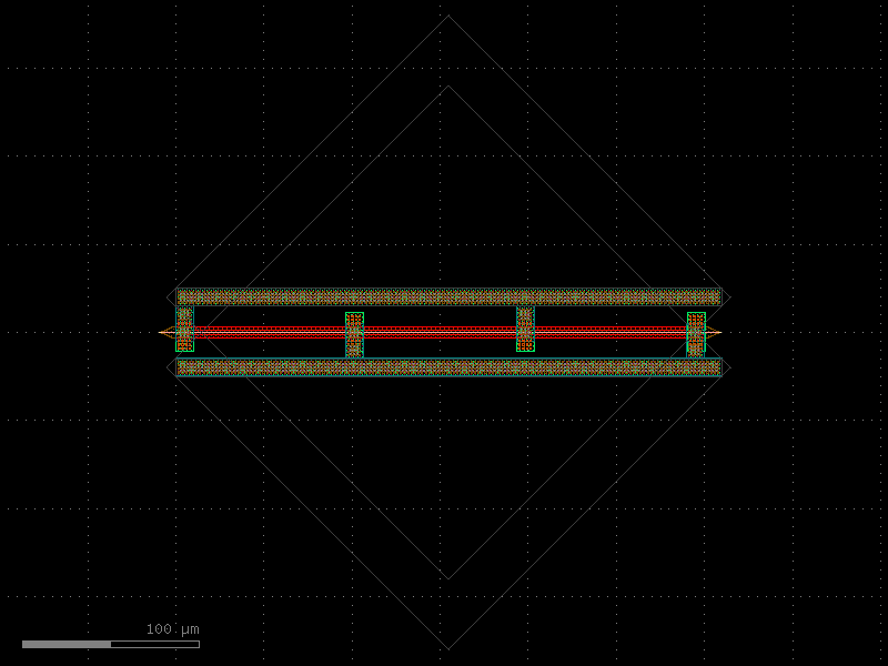
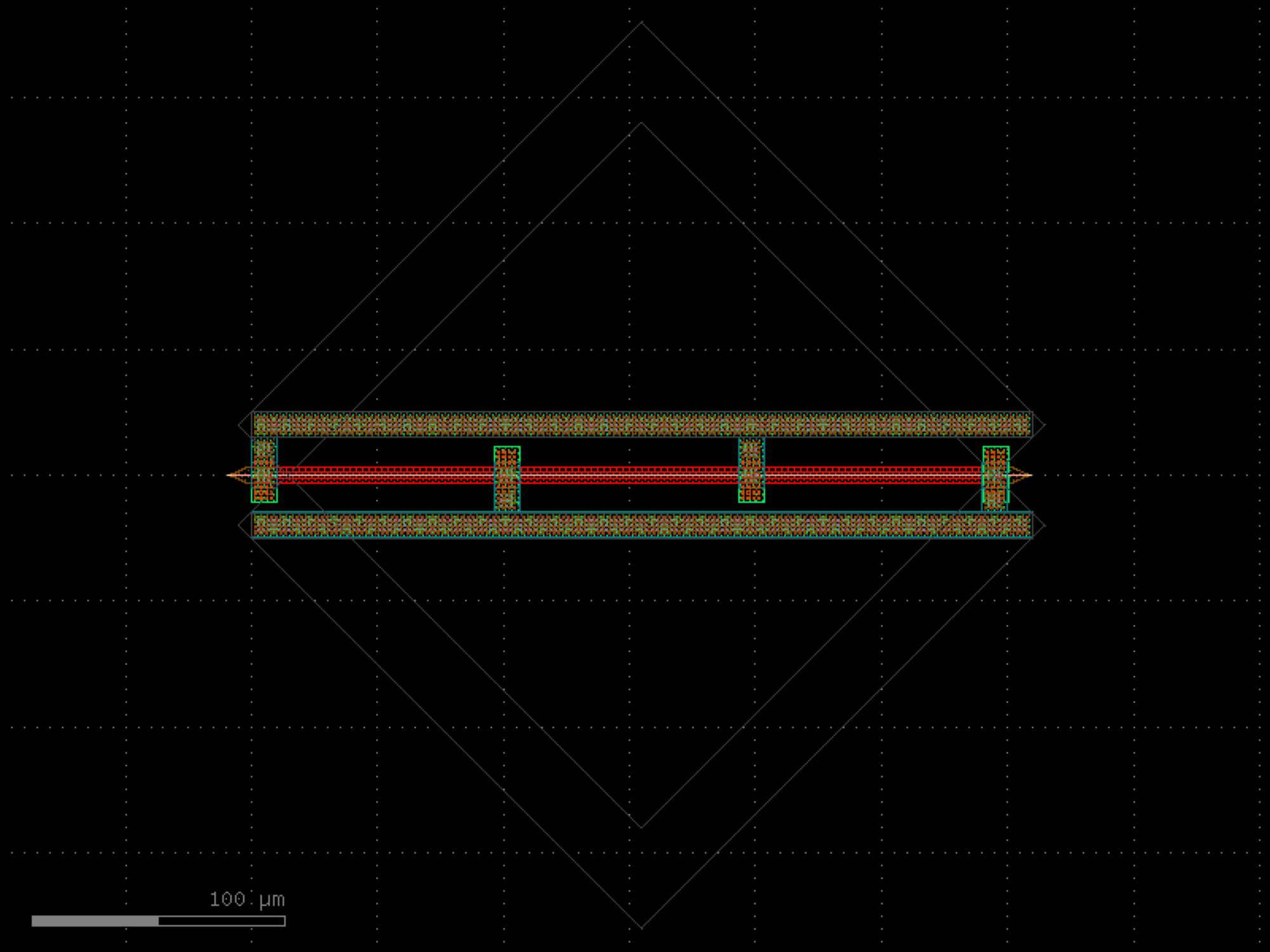

- gdsfactory.components.shapes.rect_taper(rect_width=1.0, rect_length=10.0, taper_length=5.0, taper_width=4.0, layer='WG', port_type='optical')[source]#
Returns a rectangle connected to a linear taper.
The rectangle of width rect_width and length rect_length is connected on the right to a taper that linearly expands from rect_width to taper_width over taper_length.
- Parameters:
rect_width (float) – width of the rectangular section.
rect_length (float) – length of the rectangular section.
taper_length (float) – length of the taper section.
taper_width (float) – end width of the taper.
layer (LayerSpec) – layer spec.
port_type (str | None) – None, optical, or electrical.
- Return type:
import gdsfactory as gf
gf.gpdk.PDK.activate()
c = gf.components.rect_taper(rect_width=1, rect_length=10, taper_length=5, taper_width=4, layer='WG', port_type='optical').copy()
c.draw_ports()
c.plot()
(Source code, png, hires.png, pdf)
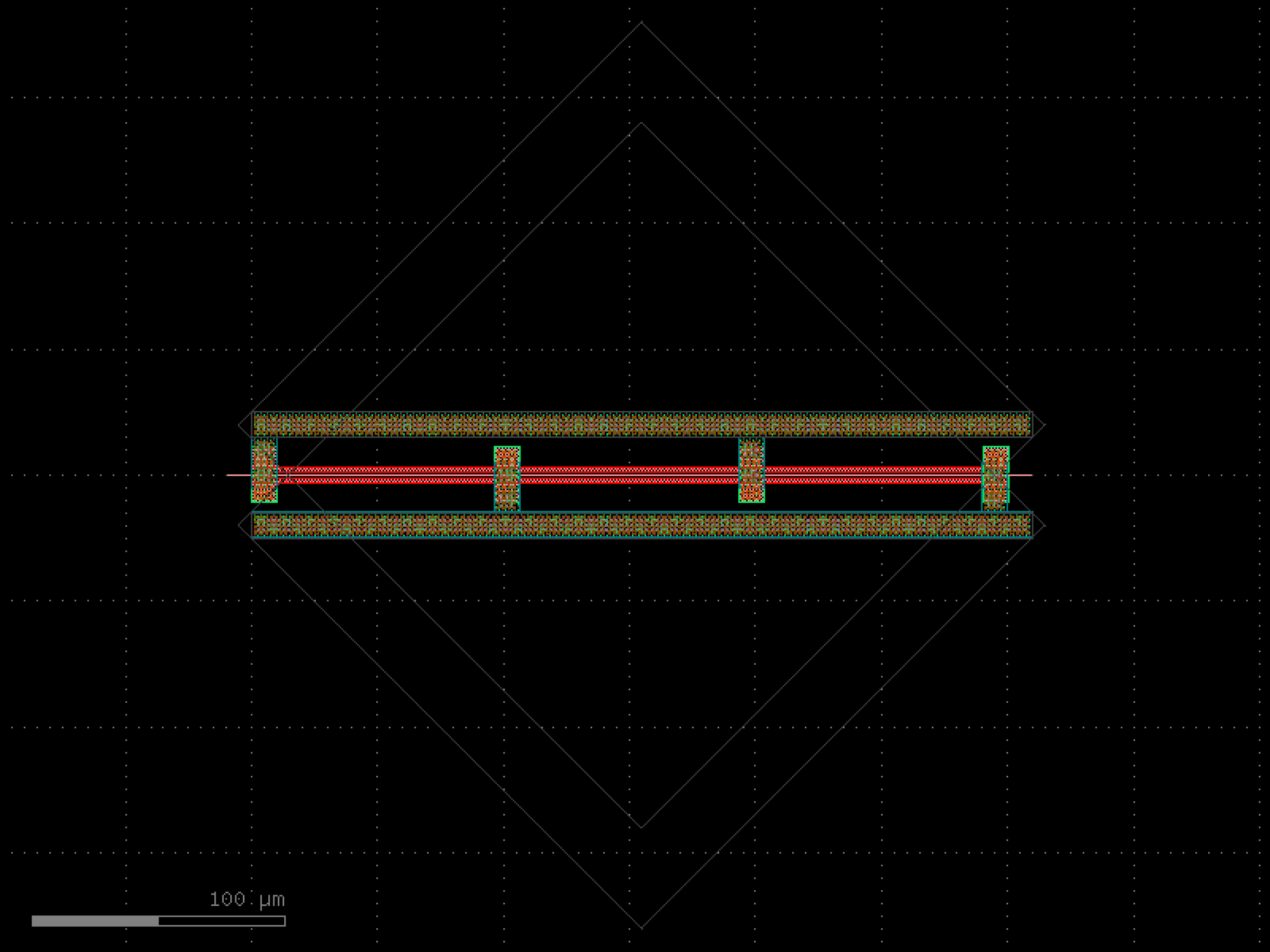
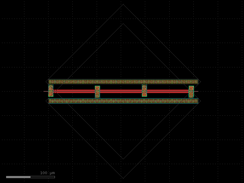
- gdsfactory.components.shapes.rectangle(size=(4.0, 2.0), layer='WG', centered=False, port_type='electrical', port_orientations=(180, 90, 0, -90))[source]#
Returns a rectangle.
- Parameters:
size (tuple[float, float]) – (tuple) Width and height of rectangle.
layer (LayerSpec) – Specific layer to put polygon geometry on.
centered (bool) – True sets center to (0, 0), False sets south-west to (0, 0).
port_type (str | None) – optical, electrical.
port_orientations (tuple[int, ...] | list[int] | None) – list of port_orientations to add. None adds no ports.
- Return type:
import gdsfactory as gf
gf.gpdk.PDK.activate()
c = gf.components.rectangle(size=(4, 2), layer='WG', centered=False, port_type='electrical', port_orientations=(180, 90, 0, -90)).copy()
c.draw_ports()
c.plot()
(Source code, png, hires.png, pdf)
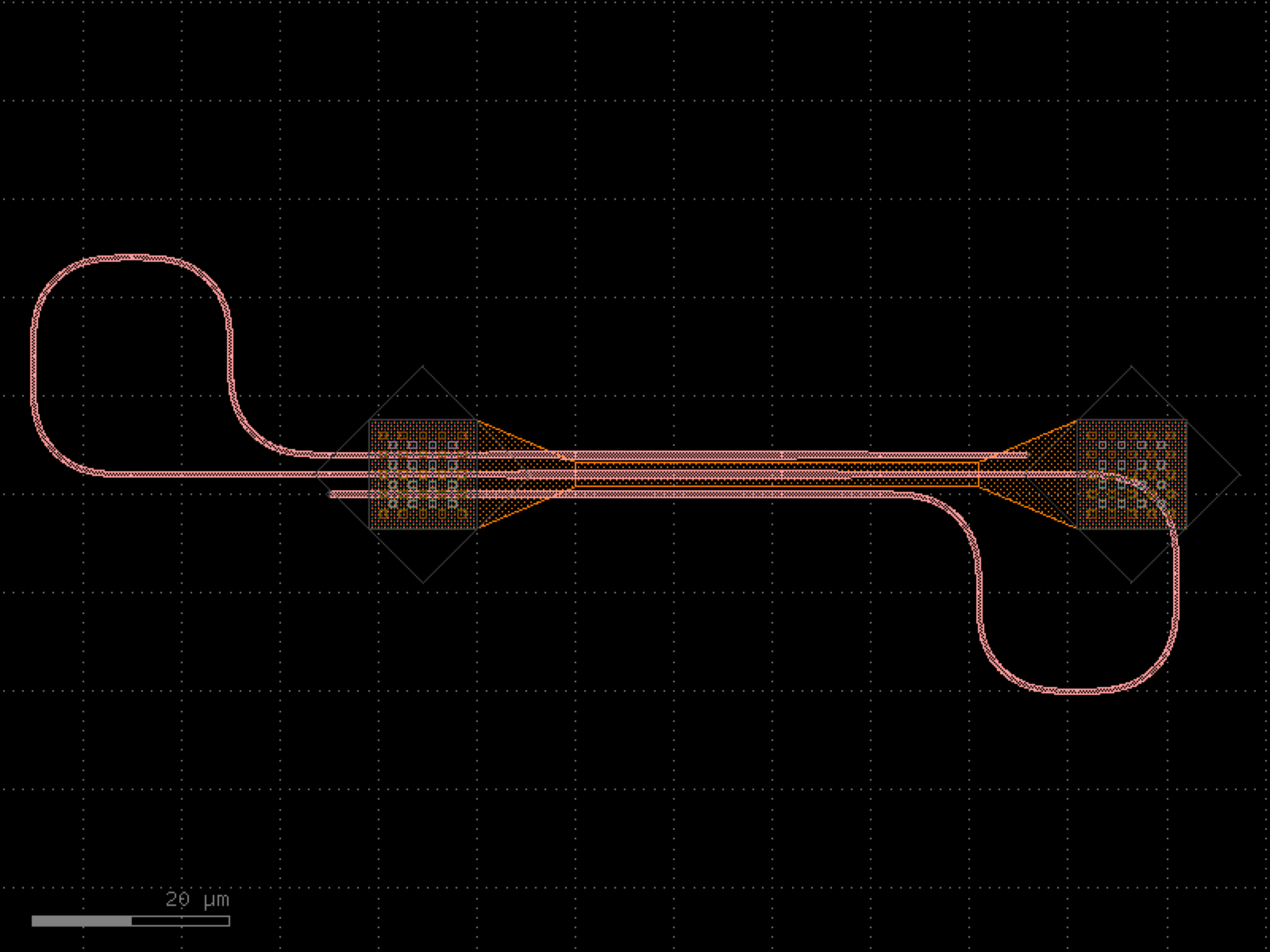

- gdsfactory.components.shapes.rectangles(size=(4.0, 2.0), offsets=None, layers=('WG', 'SLAB150'), centered=True, **kwargs)[source]#
Returns overimposed rectangles.
- Parameters:
size (tuple[float, float]) – (tuple) Width and height of rectangle.
layers (LayerSpecs) – Specific layer to put polygon geometry on.
offsets (Sequence[float] | None) – list of offsets. If None, all rectangles have a zero offset.
centered (bool) – True sets center to (0, 0), False sets south-west of first rectangle to (0, 0).
kwargs (Any) – additional arguments to pass to rectangle.
- Keyword Arguments:
port_type – optical, electrical.
port_orientations – list of port_orientations to add.
- Return type:
┌──────────────┐ │ │ │ ┌──────┐ │ │ │ │ │ │ │ ├───► │ │ │offset │ └──────┘ │ │ │ └──────────────┘
import gdsfactory as gf
gf.gpdk.PDK.activate()
c = gf.components.rectangles(size=(4, 2), layers=('WG', 'SLAB150'), centered=True).copy()
c.draw_ports()
c.plot()
(Source code, png, hires.png, pdf)
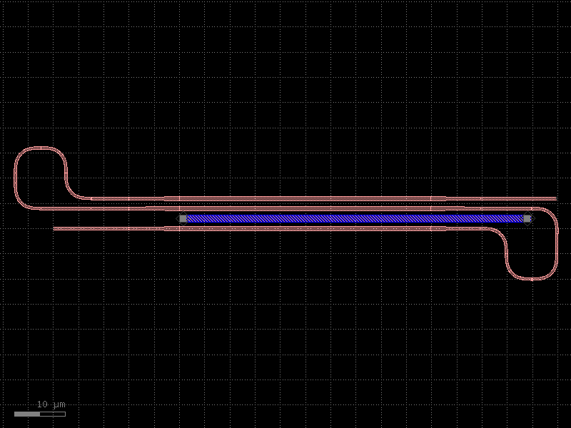
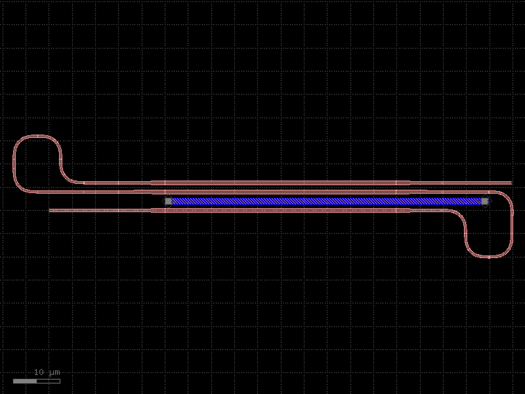

- gdsfactory.components.shapes.regular_polygon(sides=6, side_length=10, layer='WG', port_width=None, port_type='placement')[source]#
Returns a regular N-sided polygon, with ports on each edge.
- Parameters:
sides (int) – number of sides for the polygon.
side_length (float) – of the edges.
layer (LayerSpec) – Specific layer to put polygon geometry on.
port_width (float | None) – the width of port of the polygon (in electrical pads, the port width may not equal to the side length).
port_type (str | None) – optical, electrical.
- Return type:
import gdsfactory as gf
gf.gpdk.PDK.activate()
c = gf.components.regular_polygon(sides=6, side_length=10, layer='WG', port_type='placement').copy()
c.draw_ports()
c.plot()
(Source code, png, hires.png, pdf)
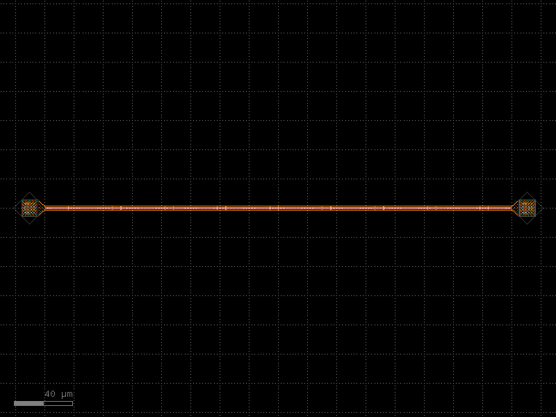
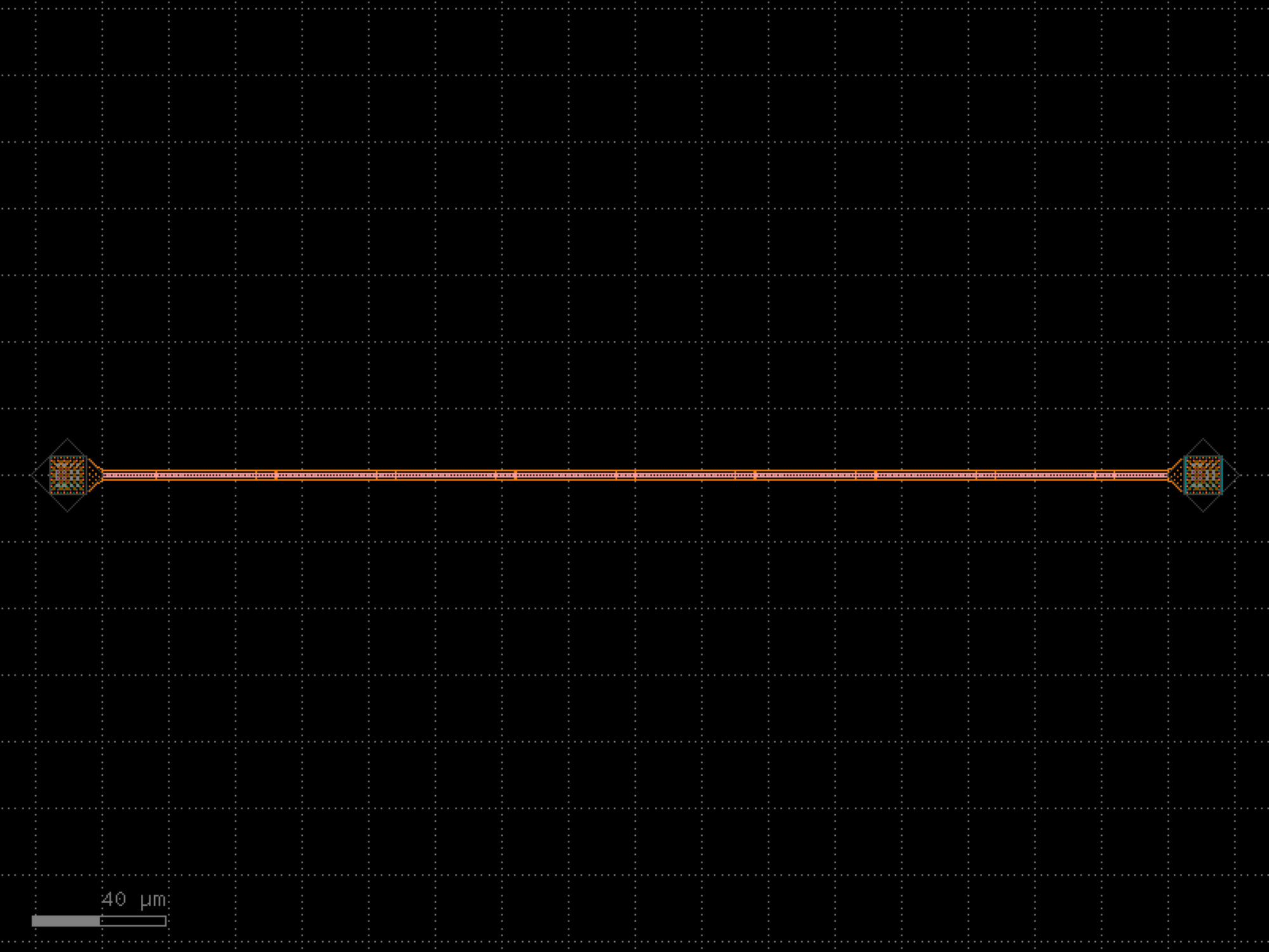
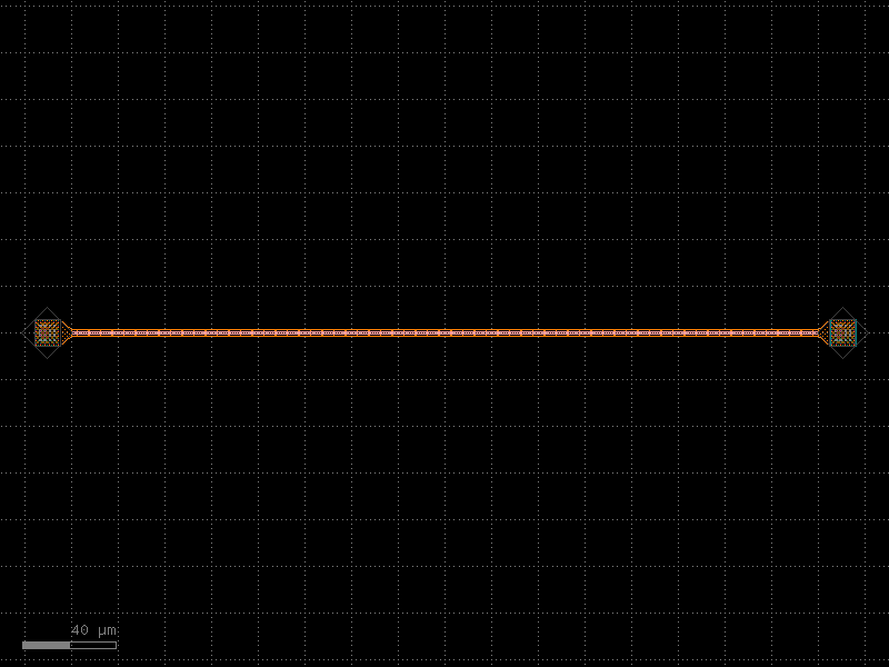
- gdsfactory.components.shapes.rounded_rectangle(width=20.0, height=10.0, corner_radius_x=3.0, corner_radius_y=None, n_corner_points=20, layer='WG', port_type=None)[source]#
Returns a rectangle with rounded corners, centered at origin.
- Parameters:
width (float) – total width of the rectangle.
height (float) – total height of the rectangle.
corner_radius_x (float) – x-radius of the corner arcs.
corner_radius_y (float | None) – y-radius of the corner arcs. Defaults to corner_radius_x.
n_corner_points (int) – number of points per corner arc.
layer (LayerSpec) – layer spec.
port_type (str | None) – None, optical, or electrical.
- Return type:
import gdsfactory as gf
gf.gpdk.PDK.activate()
c = gf.components.rounded_rectangle(width=20, height=10, corner_radius_x=3, n_corner_points=20, layer='WG').copy()
c.draw_ports()
c.plot()
(Source code, png, hires.png, pdf)
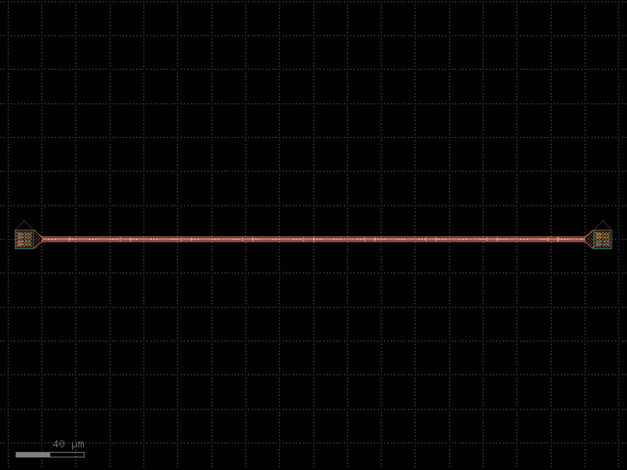
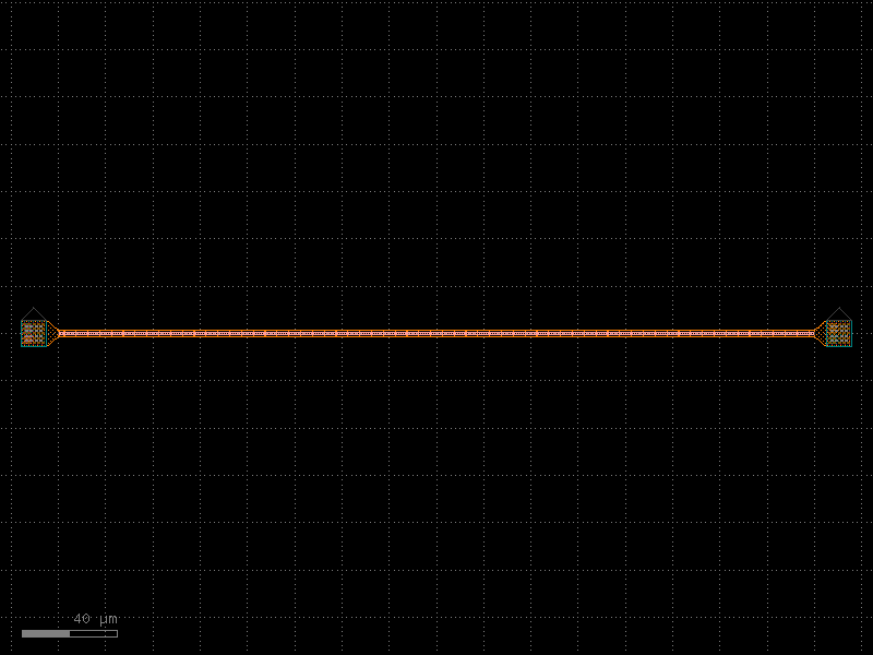
- gdsfactory.components.shapes.star(inner_radius=5.0, outer_radius=10.0, n_points=5, layer='WG')[source]#
Returns a star shape with alternating inner and outer radii.
- Parameters:
inner_radius (float) – radius of inner vertices.
outer_radius (float) – radius of outer vertices.
n_points (int) – number of star points.
layer (LayerSpec) – layer spec.
- Return type:
import gdsfactory as gf
gf.gpdk.PDK.activate()
c = gf.components.star(inner_radius=5, outer_radius=10, n_points=5, layer='WG').copy()
c.draw_ports()
c.plot()
(Source code, png, hires.png, pdf)
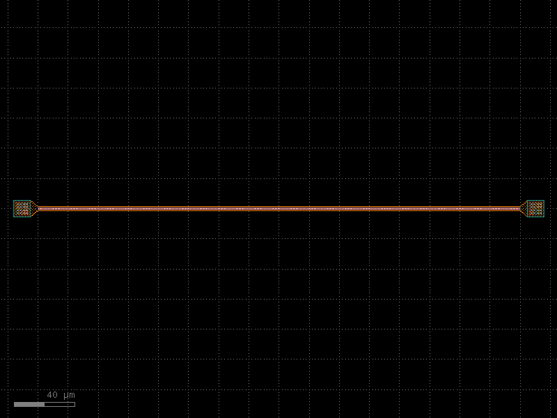
- gdsfactory.components.shapes.torus(inner_radius=5.0, outer_radius=10.0, start_angle=0.0, end_angle=360.0, angle_resolution=2.5, layer='WG', port_type=None)[source]#
Returns a torus (annular sector / ring sector) centered at origin.
- Parameters:
inner_radius (float) – inner radius.
outer_radius (float) – outer radius.
start_angle (float) – start angle in degrees.
end_angle (float) – end angle in degrees.
angle_resolution (float) – degrees per arc point.
layer (LayerSpec) – layer spec.
port_type (str | None) – None, optical, or electrical.
- Return type:
import gdsfactory as gf
gf.gpdk.PDK.activate()
c = gf.components.torus(inner_radius=5, outer_radius=10, start_angle=0, end_angle=360, angle_resolution=2.5, layer='WG').copy()
c.draw_ports()
c.plot()
(Source code, png, hires.png, pdf)
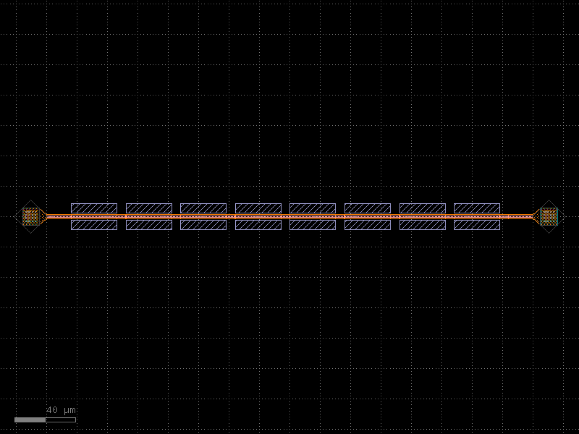
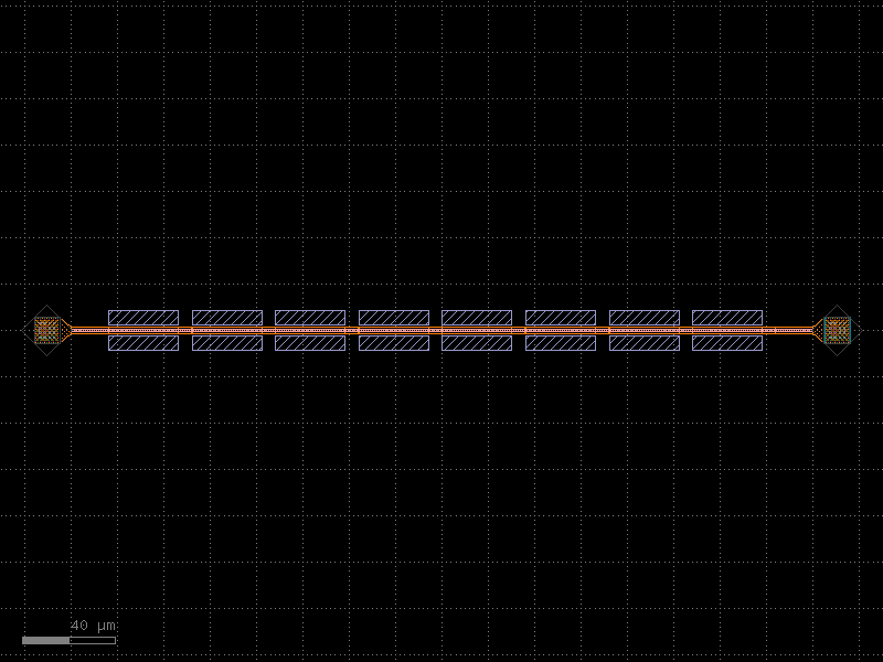
- gdsfactory.components.shapes.torus_wave(inner_radius=5.0, outer_radius=10.0, amplitude=0.5, n_oscillations=8, in_phase=True, angle_resolution=1.0, layer='WG')[source]#
Returns a torus (full ring) with sinusoidal boundary modulation.
Inner and outer boundaries oscillate sinusoidally. When in_phase=True, both boundaries are modulated in phase; when False, they are pi/2 out of phase.
- Parameters:
inner_radius (float) – mean inner radius.
outer_radius (float) – mean outer radius.
amplitude (float) – amplitude of boundary oscillation.
n_oscillations (int) – number of oscillations around the boundary.
in_phase (bool) – if True, inner and outer modulations are in phase.
angle_resolution (float) – degrees per point.
layer (LayerSpec) – layer spec.
- Return type:
import gdsfactory as gf
gf.gpdk.PDK.activate()
c = gf.components.torus_wave(inner_radius=5, outer_radius=10, amplitude=0.5, n_oscillations=8, in_phase=True, angle_resolution=1, layer='WG').copy()
c.draw_ports()
c.plot()
(Source code, png, hires.png, pdf)
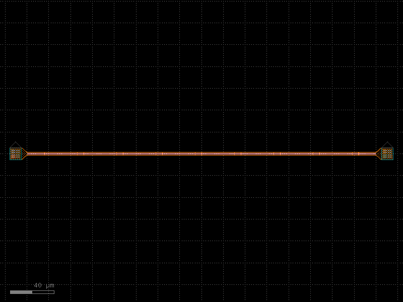
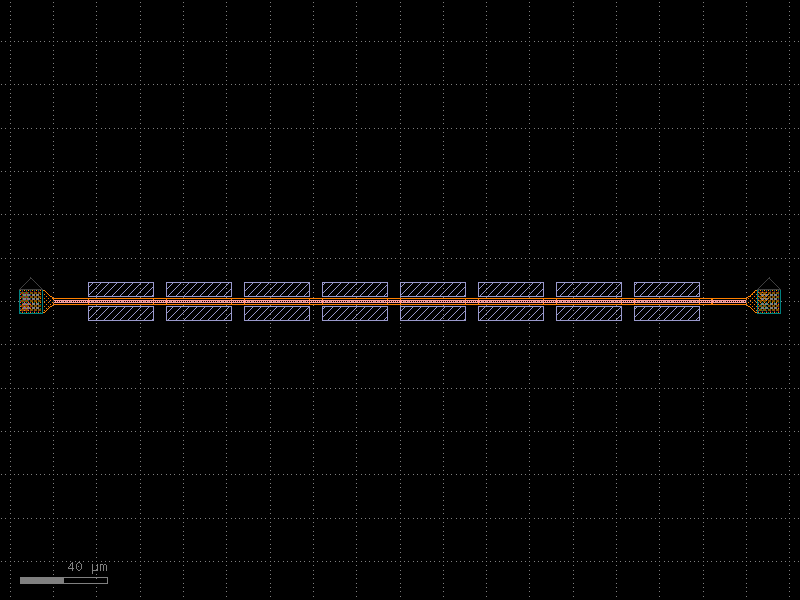
- gdsfactory.components.shapes.triangle(x=10, xtop=0, y=20, ybot=0, layer='WG')[source]#
Return triangle.
- Parameters:
x (float) – base xsize.
xtop (float) – top xsize.
y (float) – ysize.
ybot (float) – bottom ysize.
layer (LayerSpec) – layer.
- Return type:
xtop _ | \ | \ | \ y| \ | \ | \ |______|ybot x
import gdsfactory as gf
gf.gpdk.PDK.activate()
c = gf.components.triangle(x=10, xtop=0, y=20, ybot=0, layer='WG').copy()
c.draw_ports()
c.plot()
(Source code, png, hires.png, pdf)
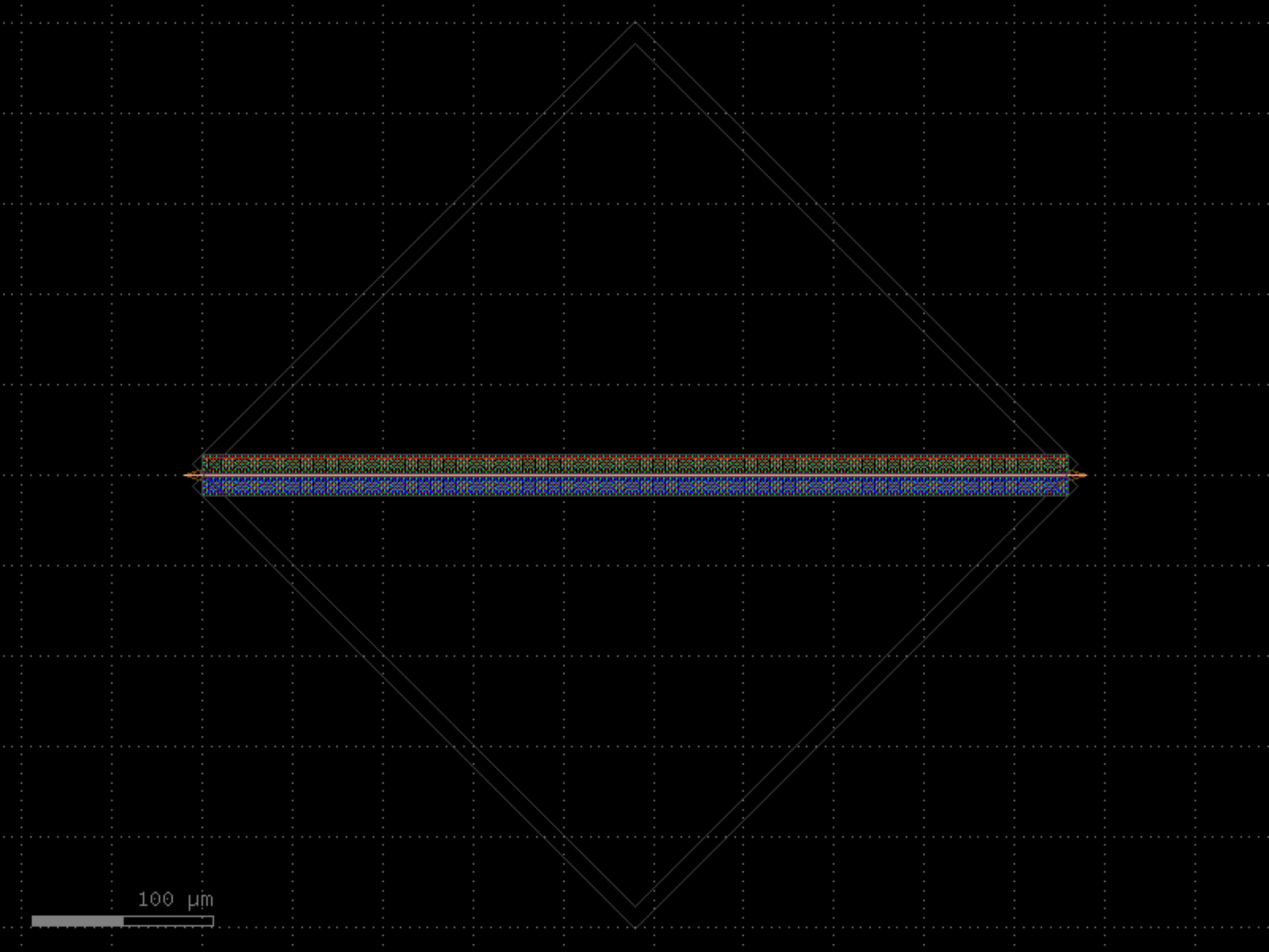
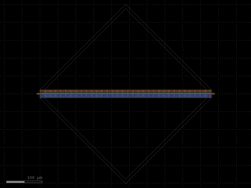
- gdsfactory.components.shapes.triangle2(spacing=3, **kwargs)[source]#
Return 2 triangles (bot, top).
- Parameters:
spacing (float) – between top and bottom.
kwargs (Any) – triangle arguments.
- Keyword Arguments:
x – base xsize.
xtop – top xsize.
y – ysize.
ybot – bottom ysize.
layer – layer.
- Return type:
_ | \ | \ | \ | \ | \ | \ | \ | | spacing | / | / | / | / | / |_/
import gdsfactory as gf
gf.gpdk.PDK.activate()
c = gf.components.triangle2(spacing=3).copy()
c.draw_ports()
c.plot()
(Source code, png, hires.png, pdf)
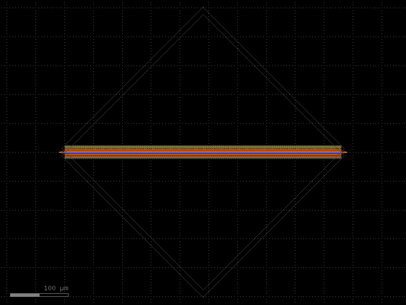
- gdsfactory.components.shapes.triangle2_thin(spacing=3, **kwargs)#
Return 2 triangles (bot, top).
- Parameters:
spacing (float) – between top and bottom.
kwargs (Any) – triangle arguments.
- Keyword Arguments:
x – base xsize.
xtop – top xsize.
y – ysize.
ybot – bottom ysize.
layer – layer.
- Return type:
_ | \ | \ | \ | \ | \ | \ | \ | | spacing | / | / | / | / | / |_/
import gdsfactory as gf
gf.gpdk.PDK.activate()
c = gf.components.triangle2_thin(spacing=3).copy()
c.draw_ports()
c.plot()
(Source code, png, hires.png, pdf)
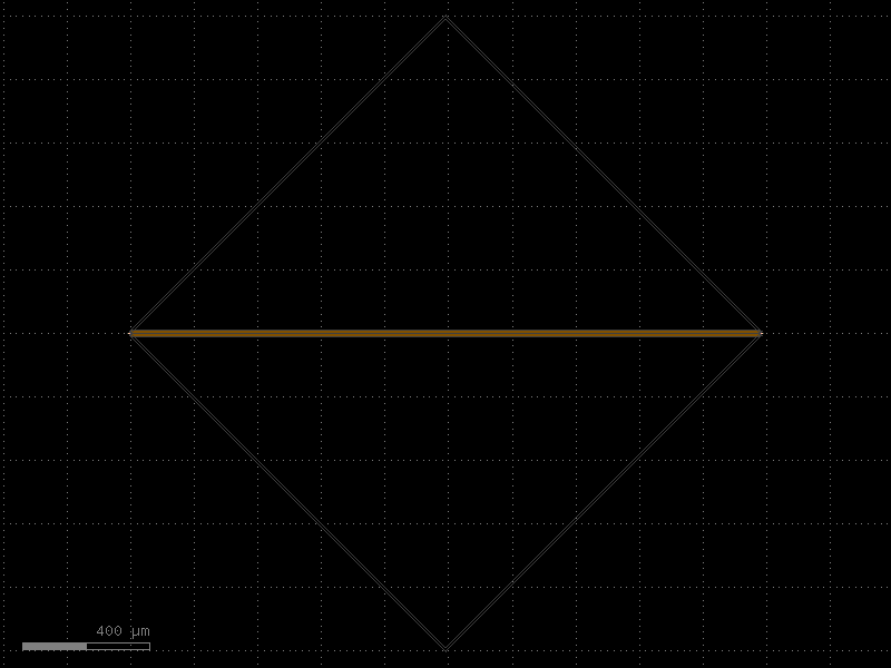

- gdsfactory.components.shapes.triangle4(**kwargs)[source]#
Return 4 triangles.
- Parameters:
kwargs (Any) – triangle arguments.
- Keyword Arguments:
x – base xsize.
xtop – top xsize.
y – ysize.
ybot – bottom ysize.
layer – layer.
- Return type:
/ | \ / | \ / | \ / | \ / | \ / | \ / | \ | | | \ | / \ | / \ | / \ | / \ | / \ |_/
import gdsfactory as gf
gf.gpdk.PDK.activate()
c = gf.components.triangle4().copy()
c.draw_ports()
c.plot()
(Source code, png, hires.png, pdf)
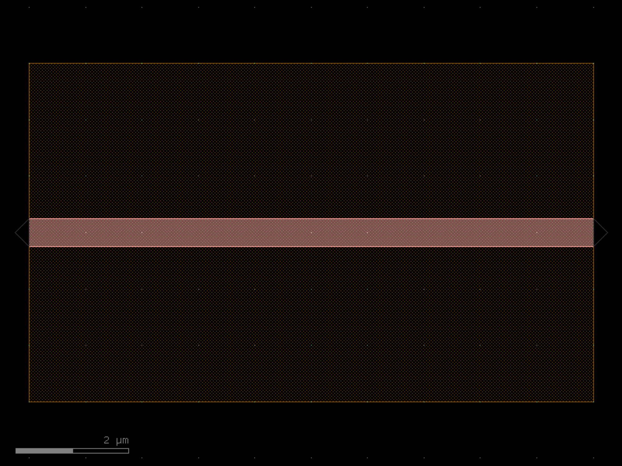
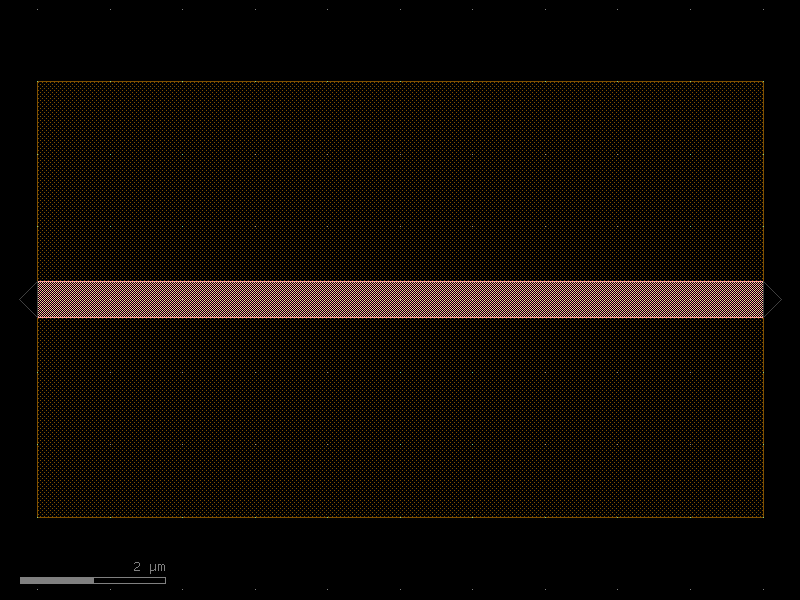
- gdsfactory.components.shapes.triangle4_thin(**kwargs)#
Return 4 triangles.
- Parameters:
kwargs (Any) – triangle arguments.
- Keyword Arguments:
x – base xsize.
xtop – top xsize.
y – ysize.
ybot – bottom ysize.
layer – layer.
- Return type:
/ | \ / | \ / | \ / | \ / | \ / | \ / | \ | | | \ | / \ | / \ | / \ | / \ | / \ |_/
import gdsfactory as gf
gf.gpdk.PDK.activate()
c = gf.components.triangle4_thin().copy()
c.draw_ports()
c.plot()
(Source code, png, hires.png, pdf)
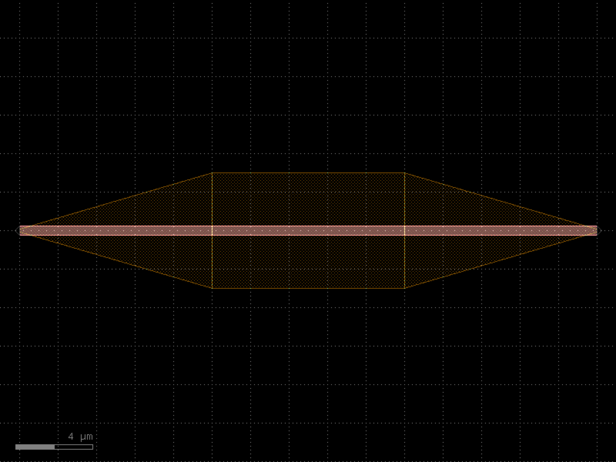
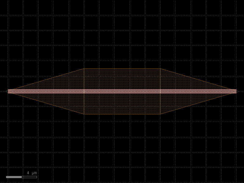
- gdsfactory.components.shapes.triangle_thin(*, x=2, xtop=0.2, y=5, ybot=0, layer='WG')#
Return triangle.
- Parameters:
x (float) – base xsize.
xtop (float) – top xsize.
y (float) – ysize.
ybot (float) – bottom ysize.
layer (LayerSpec) – layer.
- Return type:
xtop _ | \ | \ | \ y| \ | \ | \ |______|ybot x
import gdsfactory as gf
gf.gpdk.PDK.activate()
c = gf.components.triangle_thin(x=2, xtop=0.2, y=5, ybot=0, layer='WG').copy()
c.draw_ports()
c.plot()
(Source code, png, hires.png, pdf)
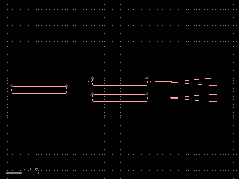

spirals#
- gdsfactory.components.spirals.delay_snake(length=1600.0, length0=0.0, length2=0.0, n=2, bend180=functools.partial(<function bend_euler>, angle=180), cross_section='strip', width=None)[source]#
Returns Snake with a starting bend and 180 bends.
- Parameters:
length (float) – total length.
length0 (float) – start length.
length2 (float) – end length.
n (int) – number of loops.
bend180 (ComponentSpec) – ubend spec.
cross_section (CrossSectionSpec) – cross_section spec.
width (float | None) – width of the waveguide. If None, it will use the width of the cross_section.
- Return type:
| length0 | >---------\ \bend180.info['length'] / |-------------------/ | |------------------->------->| length2 | delta_length | |
import gdsfactory as gf
gf.gpdk.PDK.activate()
c = gf.components.delay_snake(length=1600, length0=0, length2=0, n=2, cross_section='strip').copy()
c.draw_ports()
c.plot()
(Source code, png, hires.png, pdf)

- gdsfactory.components.spirals.delay_snake2(length=1600.0, length0=0.0, length2=0.0, n=2, bend180='bend_euler180', cross_section='strip', width=None)[source]#
Returns Snake with a starting straight and 180 bends.
Input faces west output faces east.
- Parameters:
length (float) – total length.
length0 (float) – start length.
length2 (float) – end length.
n (int) – number of loops.
bend180 (ComponentSpec) – ubend spec.
cross_section (CrossSectionSpec) – cross_section spec.
width (float | None) – width of the waveguide. If None, it will use the width of the cross_section.
- Return type:
| length0 | length1 | >---------| | bend180.length |-------------------| | |------------------->------- | length2 | delta_length | |
import gdsfactory as gf
gf.gpdk.PDK.activate()
c = gf.components.delay_snake2(length=1600, length0=0, length2=0, n=2, bend180='bend_euler180', cross_section='strip').copy()
c.draw_ports()
c.plot()
(Source code, png, hires.png, pdf)
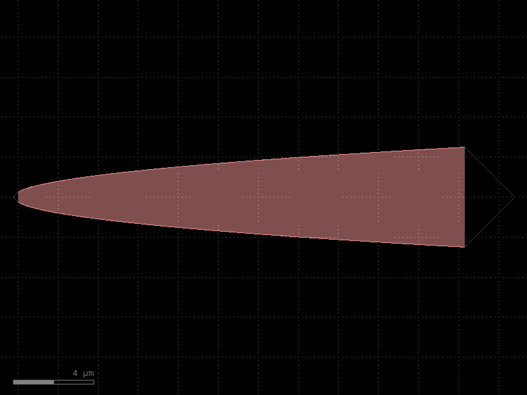
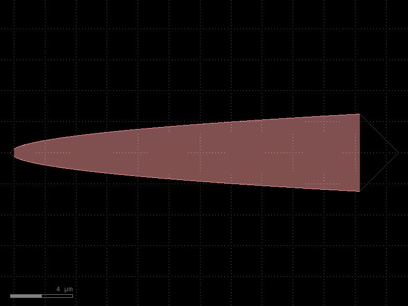
- gdsfactory.components.spirals.delay_snake_sbend(length=100.0, length1=0.0, length4=0.0, radius=5.0, waveguide_spacing=5.0, bend='bend_euler', sbend='bend_s', sbend_xsize=100.0, cross_section='strip')[source]#
Returns compact Snake with sbend in the middle.
Input port faces west and output port faces east.
- Parameters:
length (float) – total length.
length1 (float) – first straight section length in um.
length4 (float) – fourth straight section length in um.
radius (float) – u bend radius in um.
waveguide_spacing (float) – waveguide pitch in um.
bend (ComponentSpec) – bend spec.
sbend (ComponentSpec) – sbend spec.
sbend_xsize (float) – sbend size.
cross_section (CrossSectionSpec) – cross_section spec.
- Return type:
length1 <---------------------------- length2 spacing | _______ | | \ | | \ | bend1 radius | \sbend | bend2| \ | | \ | | \__| | ---------------------->-----------> length3 length4 We adjust length2 and length3
import gdsfactory as gf
gf.gpdk.PDK.activate()
c = gf.components.delay_snake_sbend(length=100, length1=0, length4=0, radius=5, waveguide_spacing=5, bend='bend_euler', sbend='bend_s', sbend_xsize=100, cross_section='strip').copy()
c.draw_ports()
c.plot()
(Source code, png, hires.png, pdf)
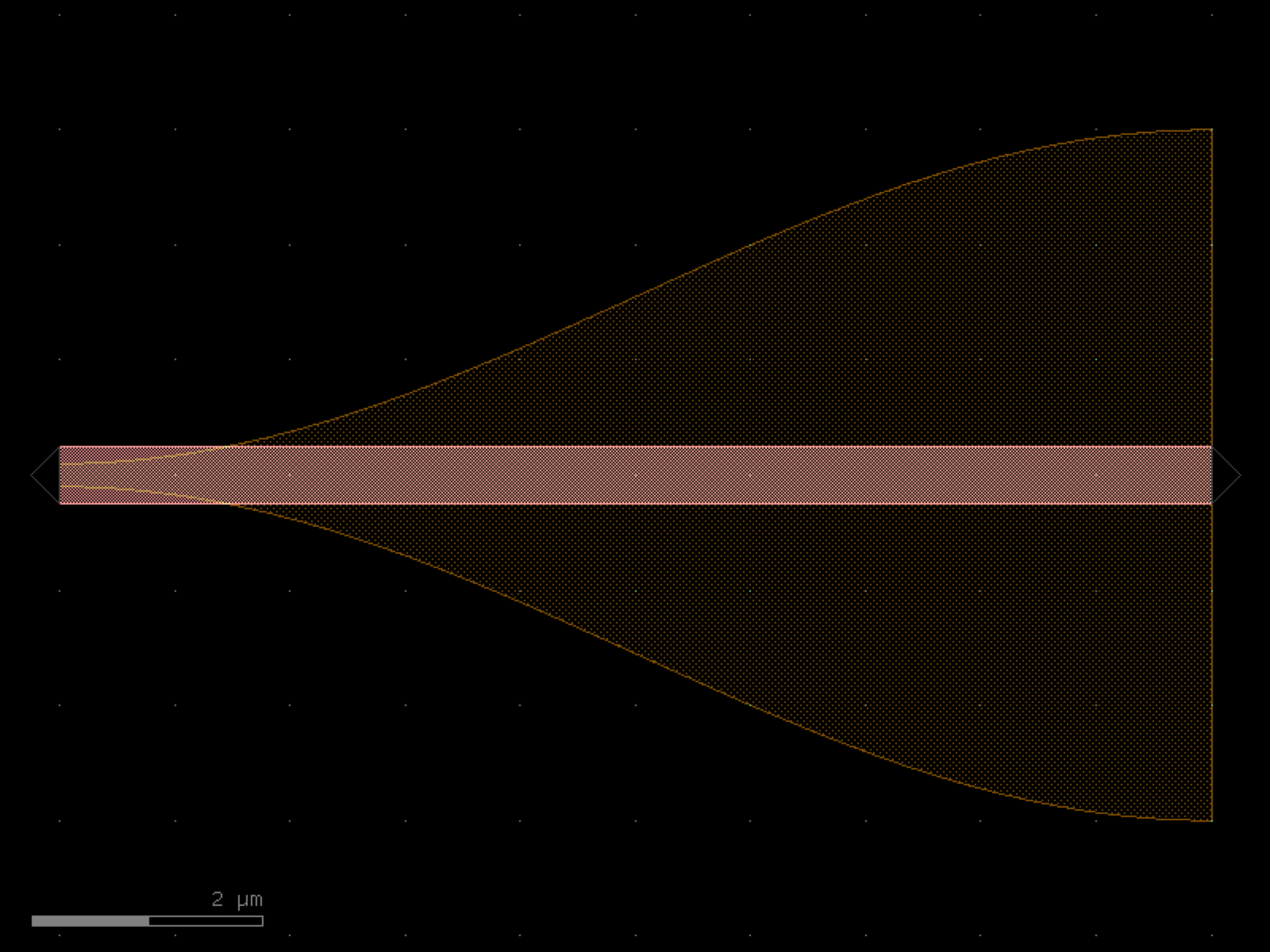

- gdsfactory.components.spirals.spiral(length=100, bend='bend_euler', straight='straight', cross_section='strip', spacing=3.0, n_loops=6)[source]#
Returns a spiral double (spiral in, and then out).
- Parameters:
length (float) – length of the spiral straight section.
bend (ComponentSpec) – bend component.
straight (ComponentSpec) – straight component.
cross_section (CrossSectionSpec) – cross_section component.
spacing (float) – spacing between the spiral loops.
n_loops (int) – number of loops.
- Return type:
import gdsfactory as gf
gf.gpdk.PDK.activate()
c = gf.components.spiral(length=100, bend='bend_euler', straight='straight', cross_section='strip', spacing=3, n_loops=6).copy()
c.draw_ports()
c.plot()
(Source code, png, hires.png, pdf)
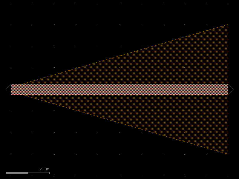
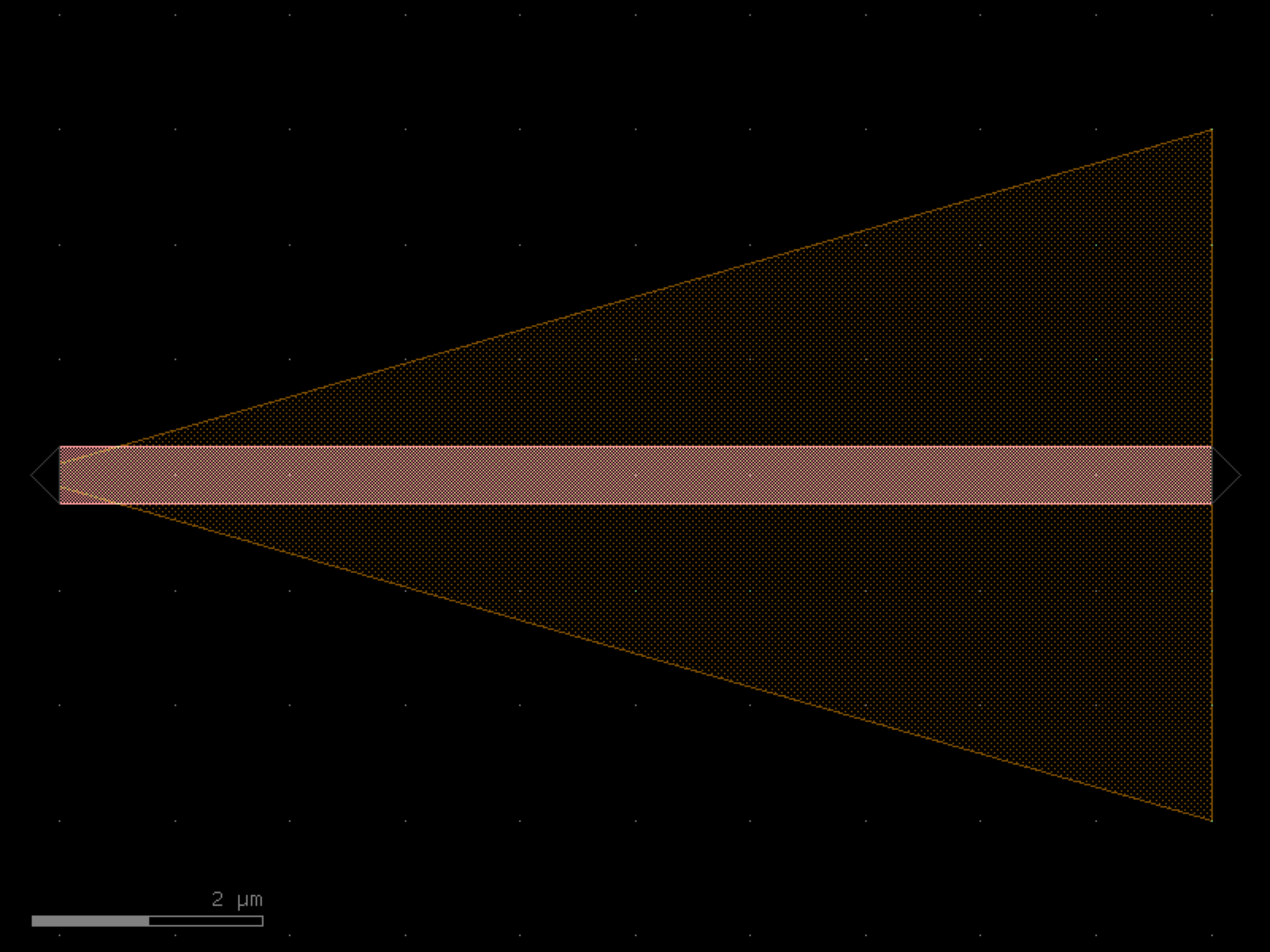

- gdsfactory.components.spirals.spiral_archimedes(width=1.0, n_turns=5, separation=2.0, angle_resolution=2.0, layer='WG')[source]#
Returns an Archimedes spiral: r = (separation + width) / (2 * pi) * theta.
- Parameters:
width (float) – width of the spiral trace.
n_turns (int) – number of turns.
separation (float) – gap between adjacent traces.
angle_resolution (float) – degrees per point.
layer (LayerSpec) – layer spec.
- Return type:
import gdsfactory as gf
gf.gpdk.PDK.activate()
c = gf.components.spiral_archimedes(width=1, n_turns=5, separation=2, angle_resolution=2, layer='WG').copy()
c.draw_ports()
c.plot()
(Source code, png, hires.png, pdf)
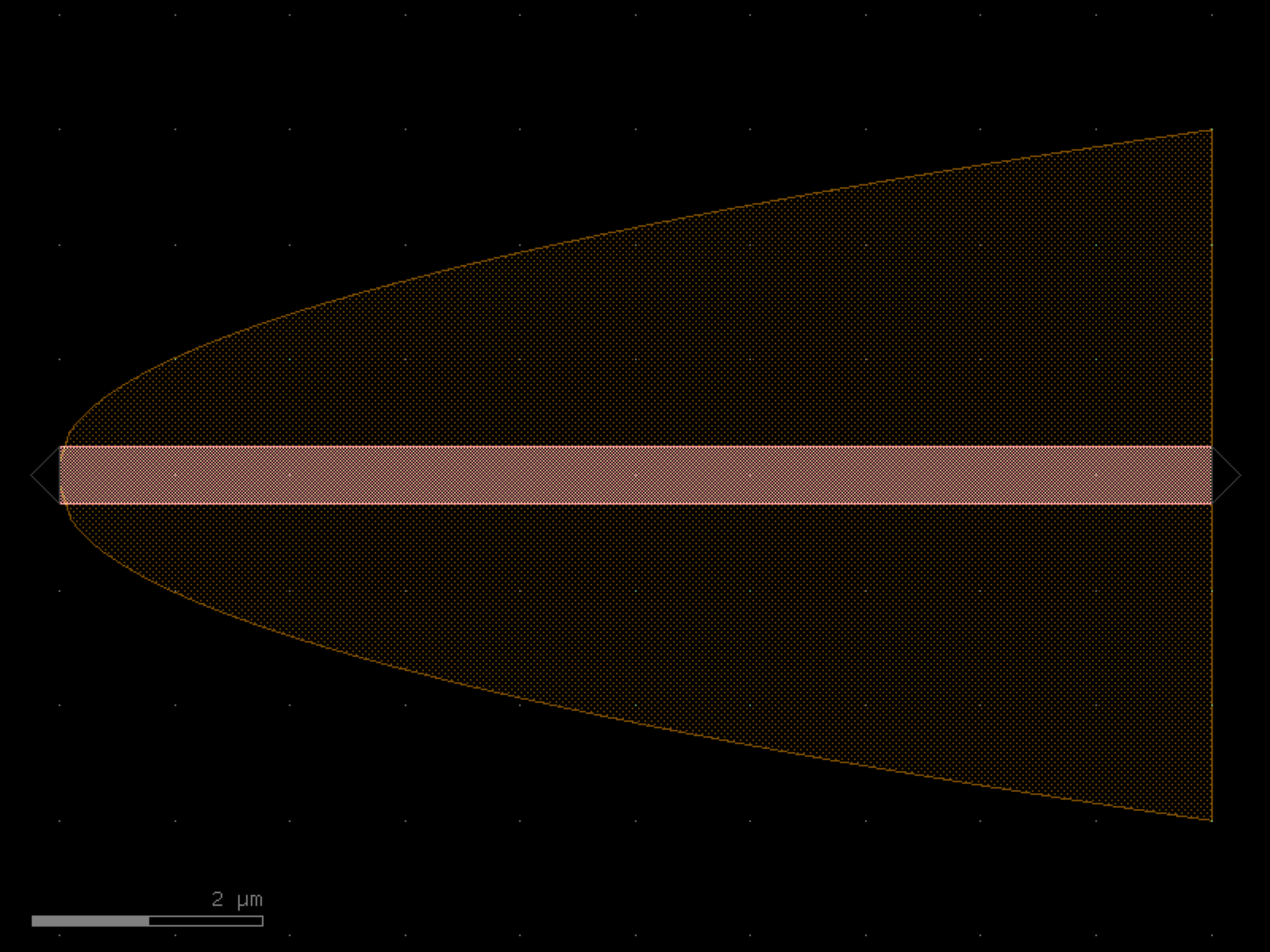
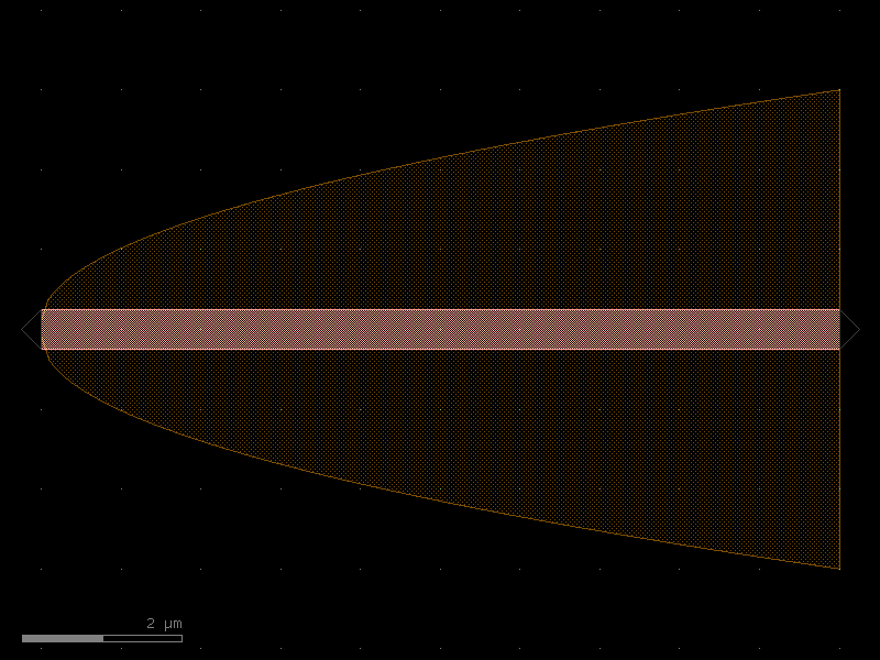
- gdsfactory.components.spirals.spiral_double(min_bend_radius=10.0, separation=2.0, number_of_loops=3, npoints=1000, cross_section='strip', bend='bend_circular')[source]#
Returns a spiral double (spiral in, and then out).
- Parameters:
min_bend_radius (float) – inner radius of the spiral.
separation (float) – separation between the loops.
number_of_loops (float) – number of loops per spiral.
npoints (int) – points for the spiral.
cross_section (CrossSectionSpec) – cross-section to extrude the structure with.
bend (ComponentSpec) – factory for the bends in the middle of the double spiral.
- Return type:
import gdsfactory as gf
gf.gpdk.PDK.activate()
c = gf.components.spiral_double(min_bend_radius=10, separation=2, number_of_loops=3, npoints=1000, cross_section='strip', bend='bend_circular').copy()
c.draw_ports()
c.plot()
(Source code, png, hires.png, pdf)
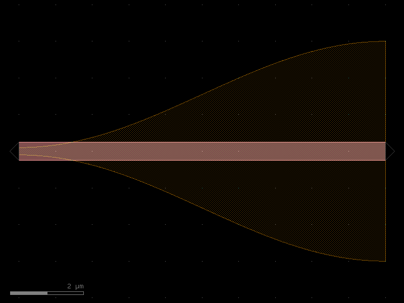
- gdsfactory.components.spirals.spiral_fermat(width=1.0, n_turns=5, a=5.0, angle_resolution=2.0, layer='WG')[source]#
Returns a Fermat spiral: r = a * sqrt(theta).
- Parameters:
width (float) – width of the spiral trace.
n_turns (int) – number of turns.
a (float) – scaling factor.
angle_resolution (float) – degrees per point.
layer (LayerSpec) – layer spec.
- Return type:
import gdsfactory as gf
gf.gpdk.PDK.activate()
c = gf.components.spiral_fermat(width=1, n_turns=5, a=5, angle_resolution=2, layer='WG').copy()
c.draw_ports()
c.plot()
(Source code, png, hires.png, pdf)
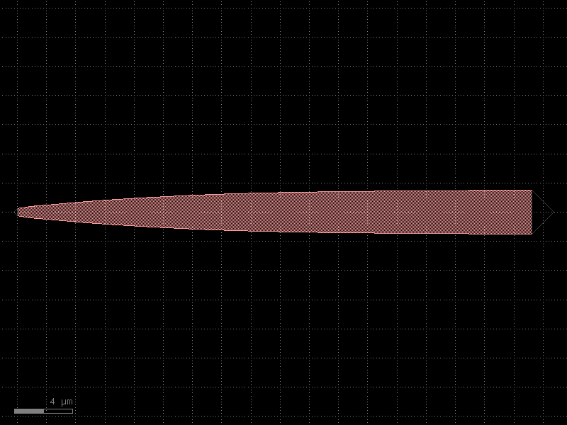
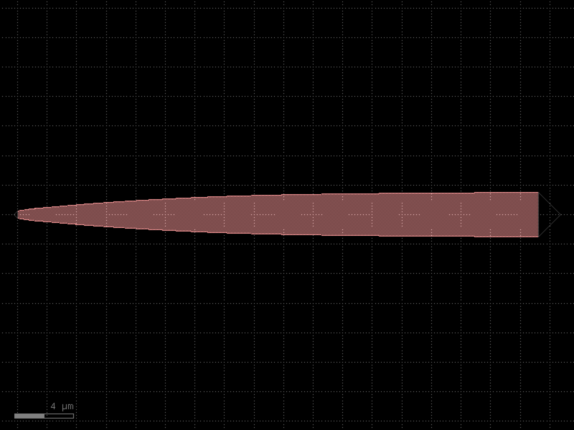

- gdsfactory.components.spirals.spiral_inductor(width=3.0, pitch=3.0, turns=16, outer_diameter=800, tail=50.0)[source]#
Generates a spiral inductor for superconducting resonator applications, particularly in qubit readout circuits.
This component creates a spiral inductor pattern commonly used in superconducting quantum circuits. The inductor is designed with a square spiral geometry, featuring inner and outer connection tails.
See J. M. Hornibrook, J. I. Colless, A. C. Mahoney, X. G. Croot, S. Blanvillain, H. Lu, A. C. Gossard, D. J. Reilly; Frequency multiplexing for readout of spin qubits. Appl. Phys. Lett. 10 March 2014; 104 (10): 103108. https://doi.org/10.1063/1.4868107
- Parameters:
width (float) – Width of the inductor track in microns. Determines the cross-sectional area of the inductor.
pitch (float) – Distance between adjacent inductor tracks in microns. Affects the coupling between turns.
turns (int) – Number of complete spiral turns. Higher values increase inductance but require more space.
outer_diameter (float) – Overall size of the inductor in microns. Defines the maximum extent of the spiral.
tail (float) – Length of the inner and outer connection tails in microns. Used for connecting to other circuit elements.
- Returns:
A GDSFactory component containing the spiral inductor pattern.
- Return type:
import gdsfactory as gf
gf.gpdk.PDK.activate()
c = gf.components.spiral_inductor(width=3, pitch=3, turns=16, outer_diameter=800, tail=50).copy()
c.draw_ports()
c.plot()
(Source code, png, hires.png, pdf)
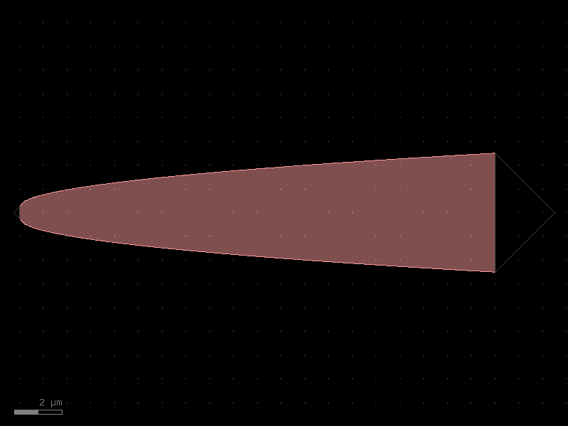
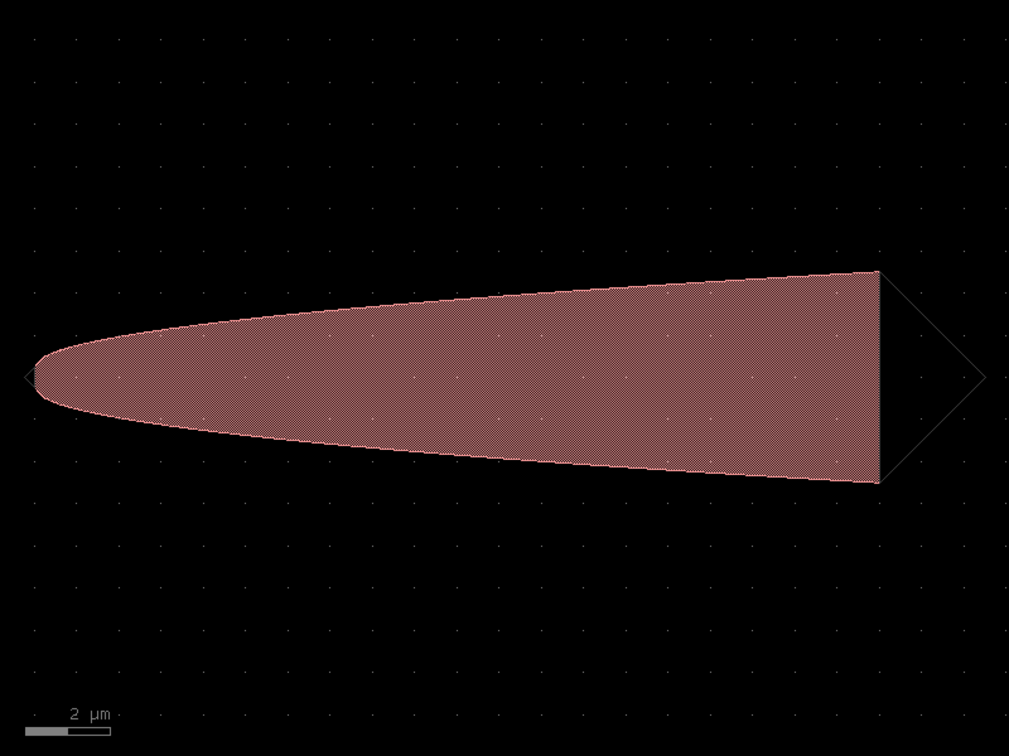

- gdsfactory.components.spirals.spiral_logarithmic(width=0.5, n_turns=4, a=1.0, b=0.1, angle_resolution=2.0, layer='WG')[source]#
Returns a logarithmic spiral: r = a * exp(b * theta).
- Parameters:
width (float) – width of the spiral trace.
n_turns (int) – number of turns.
a (float) – initial radius scaling factor.
b (float) – growth rate.
angle_resolution (float) – degrees per point.
layer (LayerSpec) – layer spec.
- Return type:
import gdsfactory as gf
gf.gpdk.PDK.activate()
c = gf.components.spiral_logarithmic(width=0.5, n_turns=4, a=1, b=0.1, angle_resolution=2, layer='WG').copy()
c.draw_ports()
c.plot()
(Source code, png, hires.png, pdf)
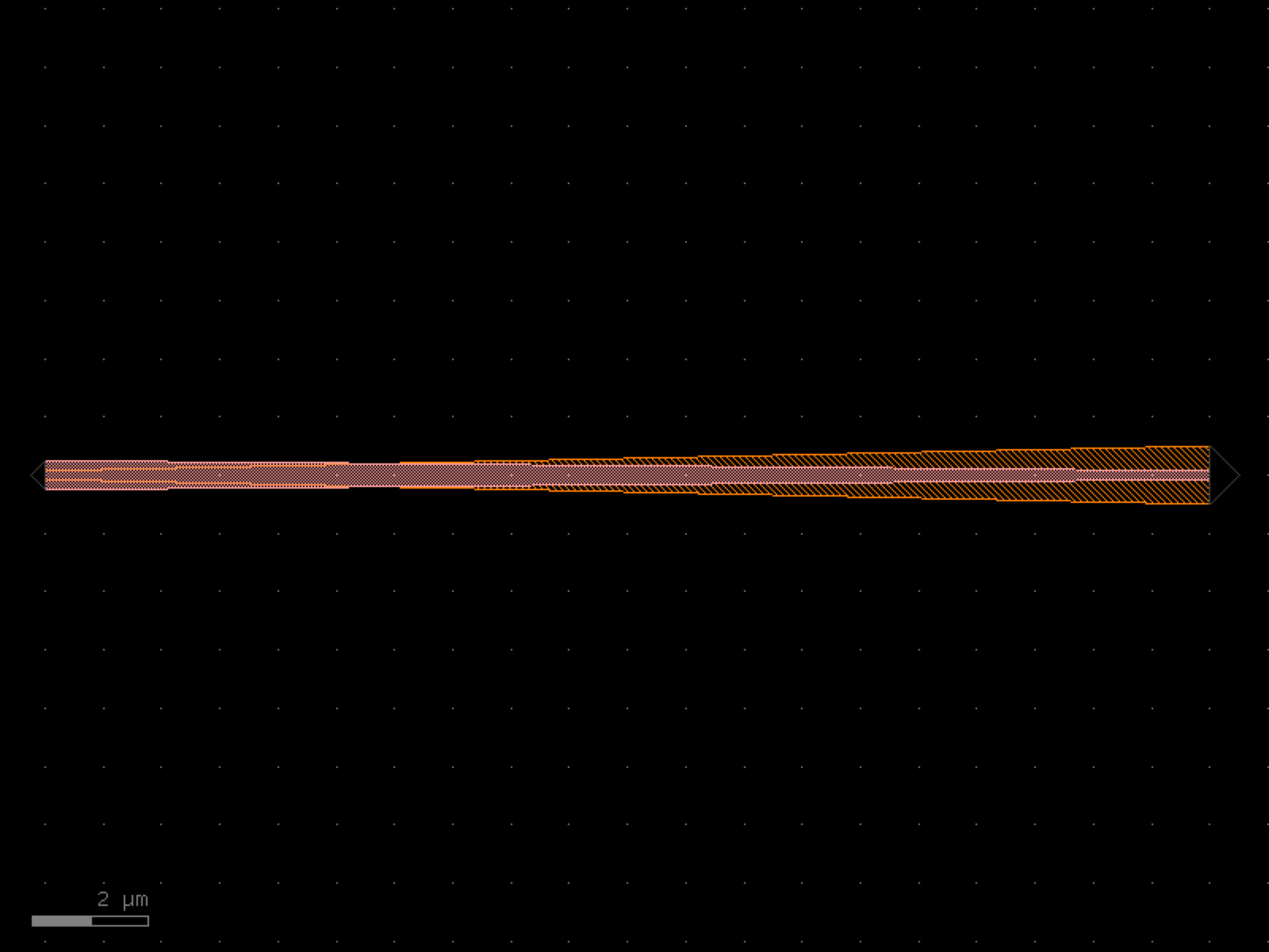
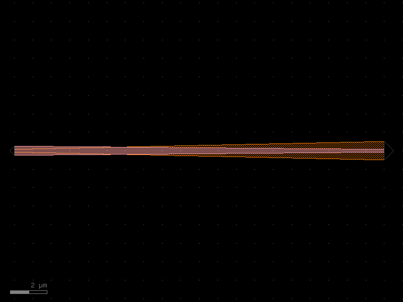
- gdsfactory.components.spirals.spiral_racetrack(min_radius=None, straight_length=20.0, spacings=(2, 2, 3, 3, 2, 2), straight=<function straight>, bend=<function bend_euler>, bend_s='bend_s', cross_section='strip', cross_section_s=None, extra_90_deg_bend=False, allow_min_radius_violation=False)[source]#
Returns Racetrack-Spiral.
- Parameters:
min_radius (float | None) – smallest radius in um.
straight_length (float) – length of the straight segments in um.
spacings (Floats) – space between the center of neighboring waveguides in um.
straight (ComponentSpec) – factory to generate the straight segments.
bend (ComponentSpec) – factory to generate the bend segments.
bend_s (ComponentSpec) – factory to generate the s-bend segments.
cross_section (CrossSectionSpec) – cross-section of the waveguides.
cross_section_s (CrossSectionSpec | None) – cross-section of the s bend waveguide (optional).
extra_90_deg_bend (bool) – if True, we add an additional straight + 90 degree bent at the output, so the output port is looking down.
allow_min_radius_violation (bool) – if True, will allow the s-bend to have a smaller radius than the minimum radius.
- Return type:
import gdsfactory as gf
gf.gpdk.PDK.activate()
c = gf.components.spiral_racetrack(straight_length=20, spacings=(2, 2, 3, 3, 2, 2), bend_s='bend_s', cross_section='strip', extra_90_deg_bend=False, allow_min_radius_violation=False).copy()
c.draw_ports()
c.plot()
(Source code, png, hires.png, pdf)
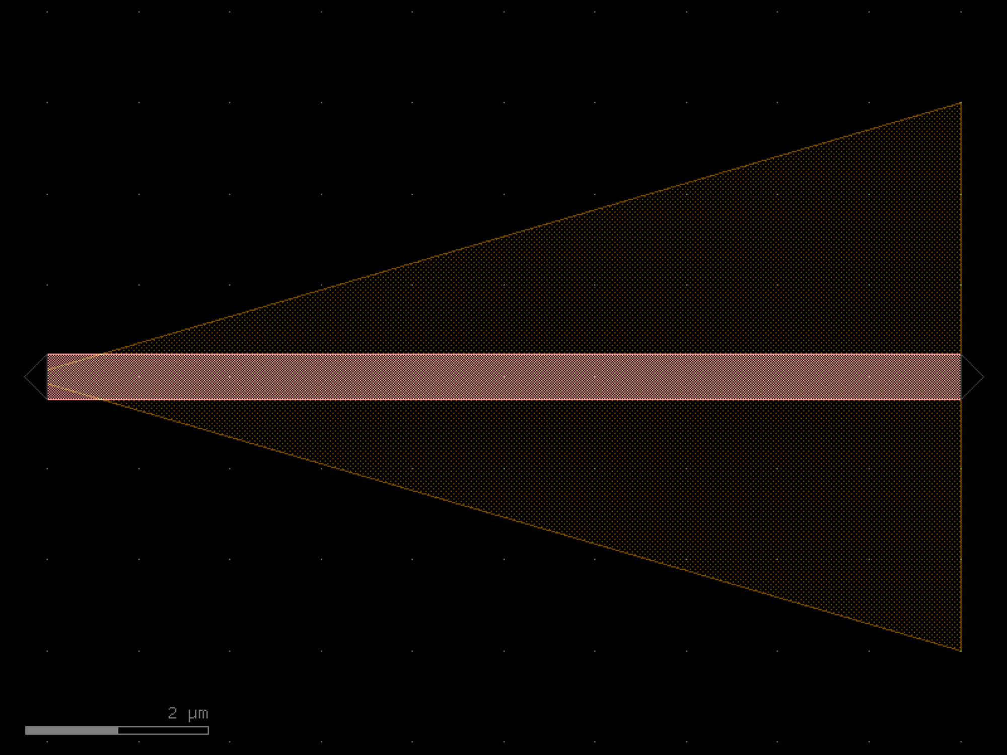
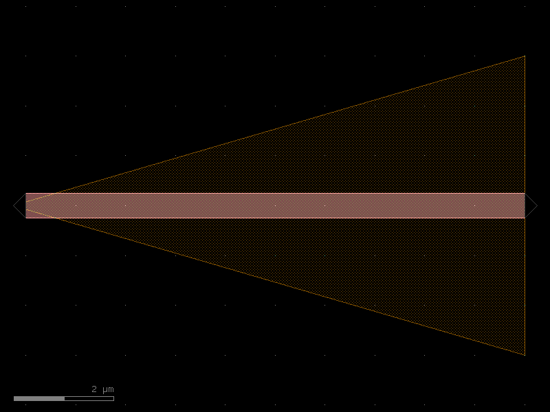
- gdsfactory.components.spirals.spiral_racetrack_fixed_length(length=1000, in_out_port_spacing=150, n_straight_sections=8, min_radius=None, min_spacing=5.0, straight=<function straight>, bend='bend_circular', bend_s='bend_s', cross_section='strip', cross_section_s=None)[source]#
Returns Racetrack-Spiral with a specified total length.
The input and output ports are aligned in y. This class is meant to be used for generating interferometers with long waveguide lengths, where the most important parameter is the length difference between the arms.
- Parameters:
length (float) – total length of the spiral from input to output ports in um.
in_out_port_spacing (float) – spacing between input and output ports of the spiral in um.
n_straight_sections (int) – total number of straight sections for the racetrack spiral. Has to be even.
min_radius (float | None) – smallest radius in um.
min_spacing (float) – minimum center-center spacing between adjacent waveguides.
straight (ComponentSpec) – factory to generate the straight segments.
bend (ComponentSpec) – factory to generate the bend segments.
bend_s (ComponentSpec) – factory to generate the s-bend segments.
cross_section (CrossSectionSpec) – cross-section of the waveguides.
cross_section_s (CrossSectionSpec | None) – cross-section of the s bend waveguide (optional).
- Return type:
import gdsfactory as gf
gf.gpdk.PDK.activate()
c = gf.components.spiral_racetrack_fixed_length(length=1000, in_out_port_spacing=150, n_straight_sections=8, min_spacing=5, bend='bend_circular', bend_s='bend_s', cross_section='strip').copy()
c.draw_ports()
c.plot()
(Source code, png, hires.png, pdf)
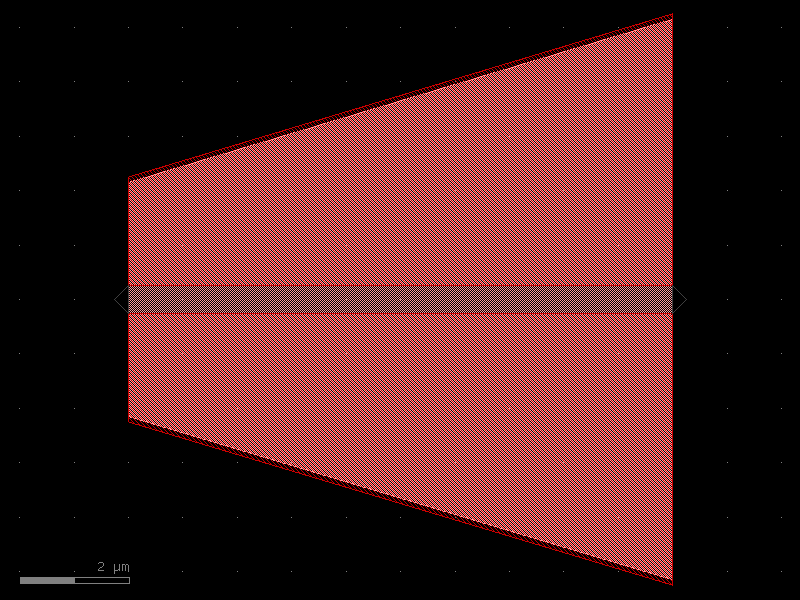

- gdsfactory.components.spirals.spiral_racetrack_heater_doped(min_radius=None, straight_length=30, spacing=2, num=8, straight=<function straight>, bend=<function bend_euler>, bend_s='bend_s', waveguide_cross_section='strip', heater_cross_section='npp')[source]#
Returns spiral racetrack with a heater between the loops.
based on https://doi.org/10.1364/OL.400230 but with the heater between the loops.
- Parameters:
min_radius (float | None) – smallest radius in um. Defaults to the radius of the cross-section.
straight_length (float) – length of the straight segments in um.
spacing (float) – space between the center of neighboring waveguides in um.
num (int) – number.
straight (ComponentSpec) – factory to generate the straight segments.
bend (ComponentSpec) – factory to generate the bend segments.
bend_s (ComponentSpec) – factory to generate the s-bend segments.
waveguide_cross_section (CrossSectionSpec) – cross-section of the waveguides.
heater_cross_section (CrossSectionSpec) – cross-section of the heater.
- Return type:
import gdsfactory as gf
gf.gpdk.PDK.activate()
c = gf.components.spiral_racetrack_heater_doped(straight_length=30, spacing=2, num=8, bend_s='bend_s', waveguide_cross_section='strip', heater_cross_section='npp').copy()
c.draw_ports()
c.plot()
(Source code, png, hires.png, pdf)
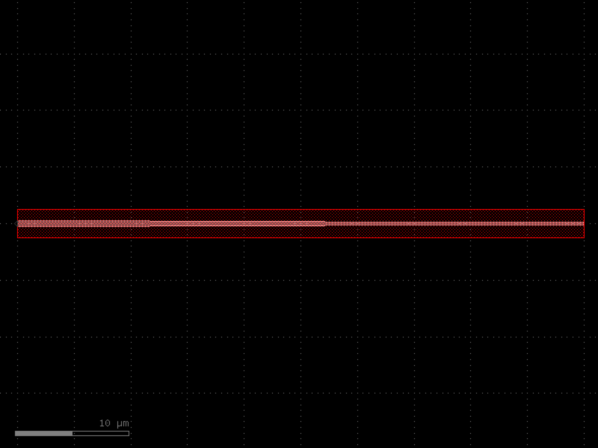
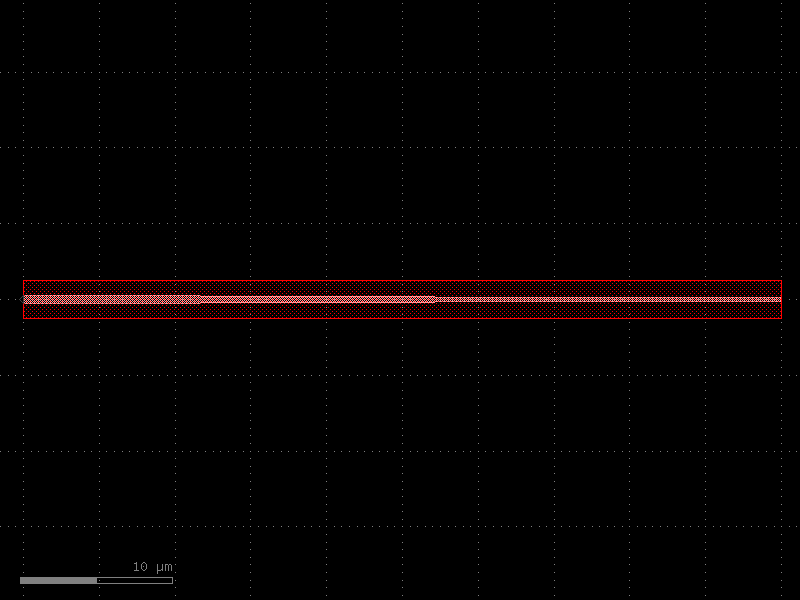
- gdsfactory.components.spirals.spiral_racetrack_heater_metal(min_radius=None, straight_length=30, spacing=2, num=8, straight=<function straight>, bend=<function bend_euler>, bend_s='bend_s', waveguide_cross_section='strip', heater_cross_section='heater_metal', via_stack='via_stack_heater_mtop')[source]#
Returns spiral racetrack with a heater above.
based on https://doi.org/10.1364/OL.400230 .
- Parameters:
min_radius (float | None) – smallest radius. Defaults to the radius of the cross-section.
straight_length (float) – length of the straight segments.
spacing (float) – space between the center of neighboring waveguides.
num (int) – number of loops.
straight (ComponentSpec) – factory to generate the straight segments.
bend (ComponentSpec) – factory to generate the bend segments.
bend_s (ComponentSpec) – factory to generate the s-bend segments.
waveguide_cross_section (CrossSectionSpec) – cross-section of the waveguides.
heater_cross_section (CrossSectionSpec) – cross-section of the heater.
via_stack (ComponentSpec | None) – via stack to connect the heater to the metal layer.
- Return type:
import gdsfactory as gf
gf.gpdk.PDK.activate()
c = gf.components.spiral_racetrack_heater_metal(straight_length=30, spacing=2, num=8, bend_s='bend_s', waveguide_cross_section='strip', heater_cross_section='heater_metal', via_stack='via_stack_heater_mtop').copy()
c.draw_ports()
c.plot()
(Source code, png, hires.png, pdf)

- gdsfactory.components.spirals.spiral_rectangular(n_turns=4, width=1.0, start_length=10.0, pitch=3.0, layer='WG')[source]#
Returns a rectangular/Manhattan spiral as a polygon.
Each segment grows by pitch per half-turn, building an expanding rectangular spiral. The outline is created with the given width offset.
- Parameters:
n_turns (int) – number of full turns.
width (float) – width of the spiral trace.
start_length (float) – initial segment length.
pitch (float) – spacing between adjacent turns (center-to-center).
layer (LayerSpec) – layer spec.
- Return type:
import gdsfactory as gf
gf.gpdk.PDK.activate()
c = gf.components.spiral_rectangular(n_turns=4, width=1, start_length=10, pitch=3, layer='WG').copy()
c.draw_ports()
c.plot()
(Source code, png, hires.png, pdf)
superconductors#
- gdsfactory.components.superconductors.hline(length=10.0, width=0.5, layer='WG', port_type='optical')[source]#
Creates a horizontal straight line component with ports on east and west sides.
This component is commonly used in photonic and superconducting circuits as a basic waveguide or transmission line element. It creates a rectangular polygon with ports at both ends for easy connection to other components.
- Parameters:
length (float) – Length of the line in microns. Must be positive.
width (float) – Width of the line in microns. Must be positive.
layer (LayerSpec) – Layer specification for the line (default: “WG”). Can be a string or a tuple of (layer, datatype).
port_type (str) – Type of port to create (default: “optical”). Common values are “optical” for photonic circuits or “electrical” for superconducting circuits.
- Returns:
- A gdsfactory Component object containing:
A rectangular polygon representing the line
Two ports named “o1” (west) and “o2” (east)
Component info with width and length values
- Return type:
Note
The line is centered vertically at y=0
Port “o1” is at x=0 with orientation 180° (west)
Port “o2” is at x=length with orientation 0° (east)
If length or width is 0 or negative, no polygon is created but ports are still added
import gdsfactory as gf
gf.gpdk.PDK.activate()
c = gf.components.hline(length=10, width=0.5, layer='WG', port_type='optical').copy()
c.draw_ports()
c.plot()
(Source code, png, hires.png, pdf)
- gdsfactory.components.superconductors.optimal_90deg(width=100, num_pts=15, length_adjust=1, layer=(1, 0))[source]#
Returns optimally-rounded 90 degree bend that is sharp on the outer corner.
- Parameters:
width (float) – Width of the ports on either side of the bend.
num_pts (int) – The number of points comprising the curved section of the bend.
length_adjust (float) – Adjusts the length of the non-curved portion of the bend.
layer (LayerSpec) – Specific layer(s) to put polygon geometry on.
- Return type:
Notes
Optimal structure from https://doi.org/10.1103/PhysRevB.84.174510 Clem, J., & Berggren, K. (2011). Geometry-dependent critical currents in superconducting nanocircuits. Physical Review B, 84(17), 1-27.
import gdsfactory as gf
gf.gpdk.PDK.activate()
c = gf.components.optimal_90deg(width=100, num_pts=15, length_adjust=1, layer=(1, 0)).copy()
c.draw_ports()
c.plot()
(Source code, png, hires.png, pdf)

- gdsfactory.components.superconductors.optimal_hairpin(width=0.2, pitch=0.6, length=10, turn_ratio=4, num_pts=50, layer=(1, 0))[source]#
Returns an optimally-rounded hairpin geometry, with a 180 degree turn.
based on phidl.geometry
- Parameters:
width (float) – Width of the hairpin leads.
pitch (float) – Distance between the two hairpin leads. Must be greater than width.
length (float) – Length of the hairpin from the connectors to the opposite end of the curve.
turn_ratio (float) – int or float Specifies how much of the hairpin is dedicated to the 180 degree turn. A turn_ratio of 10 will result in 20% of the hairpin being comprised of the turn.
num_pts (int) – Number of points constituting the 180 degree turn.
layer (LayerSpec) – Specific layer(s) to put polygon geometry on.
- Return type:
Notes
Hairpin pitch must be greater than width.
Optimal structure from https://doi.org/10.1103/PhysRevB.84.174510 Clem, J., & Berggren, K. (2011). Geometry-dependent critical currents in superconducting nanocircuits. Physical Review B, 84(17), 1-27.
import gdsfactory as gf
gf.gpdk.PDK.activate()
c = gf.components.optimal_hairpin(width=0.2, pitch=0.6, length=10, turn_ratio=4, num_pts=50, layer=(1, 0)).copy()
c.draw_ports()
c.plot()
(Source code, png, hires.png, pdf)

- gdsfactory.components.superconductors.optimal_step(start_width=10, end_width=22, num_pts=50, width_tol=0.001, anticrowding_factor=1.2, symmetric=False, layer=(1, 0))[source]#
Returns an optimally-rounded step geometry.
- Parameters:
start_width (float) – Width of the connector on the left end of the step.
end_width (float) – Width of the connector on the right end of the step.
num_pts (int) – number of points comprising the entire step geometry.
width_tol (float) – Point at which to terminate the calculation of the optimal step
anticrowding_factor (float) – Factor to reduce current crowding by elongating the structure and reducing the curvature
symmetric (bool) – If True, adds a mirrored copy of the step across the x-axis to the geometry and adjusts the width of the ports.
layer (LayerSpec) – layer spec to put polygon geometry on.
- Return type:
based on phidl.geometry Optimal structure from https://doi.org/10.1103/PhysRevB.84.174510 Clem, J., & Berggren, K. (2011). Geometry-dependent critical currents in superconducting nanocircuits. Physical Review B, 84(17), 1-27.
import gdsfactory as gf
gf.gpdk.PDK.activate()
c = gf.components.optimal_step(start_width=10, end_width=22, num_pts=50, width_tol=0.001, anticrowding_factor=1.2, symmetric=False, layer=(1, 0)).copy()
c.draw_ports()
c.plot()
(Source code, png, hires.png, pdf)

- gdsfactory.components.superconductors.snspd(wire_width=0.2, wire_pitch=0.6, size=(10, 8), num_squares=None, turn_ratio=4, terminals_same_side=False, layer=(1, 0), port_type='electrical')[source]#
Creates an optimally-rounded SNSPD.
- Parameters:
wire_width (float) – Width of the wire.
wire_pitch (float) – Distance between two adjacent wires. Must be greater than width.
size (tuple[float, float]) – Float2 (width, height) of the rectangle formed by the outer boundary of the SNSPD.
num_squares (int | None) – int | None = None Total number of squares inside the SNSPD length.
turn_ratio (float) – float Specifies how much of the SNSPD width is dedicated to the 180 degree turn. A turn_ratio of 10 will result in 20% of the width being comprised of the turn.
terminals_same_side (bool) – If True, both ports will be located on the same side of the SNSPD.
layer (LayerSpec) – layer spec to put polygon geometry on.
port_type (str) – type of port to add to the component.
- Return type:
import gdsfactory as gf
gf.gpdk.PDK.activate()
c = gf.components.snspd(wire_width=0.2, wire_pitch=0.6, size=(10, 8), turn_ratio=4, terminals_same_side=False, layer=(1, 0), port_type='electrical').copy()
c.draw_ports()
c.plot()
(Source code, png, hires.png, pdf)
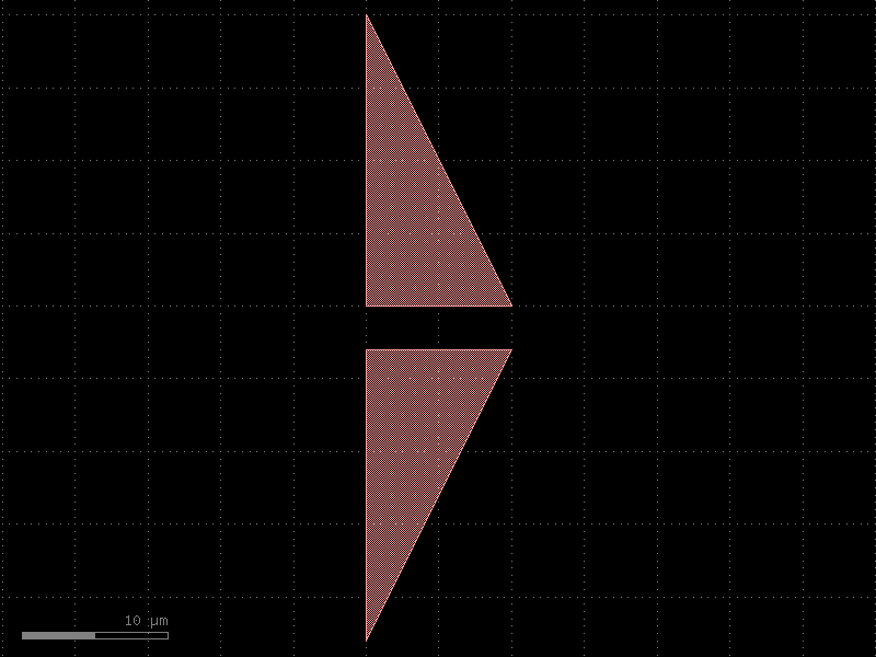
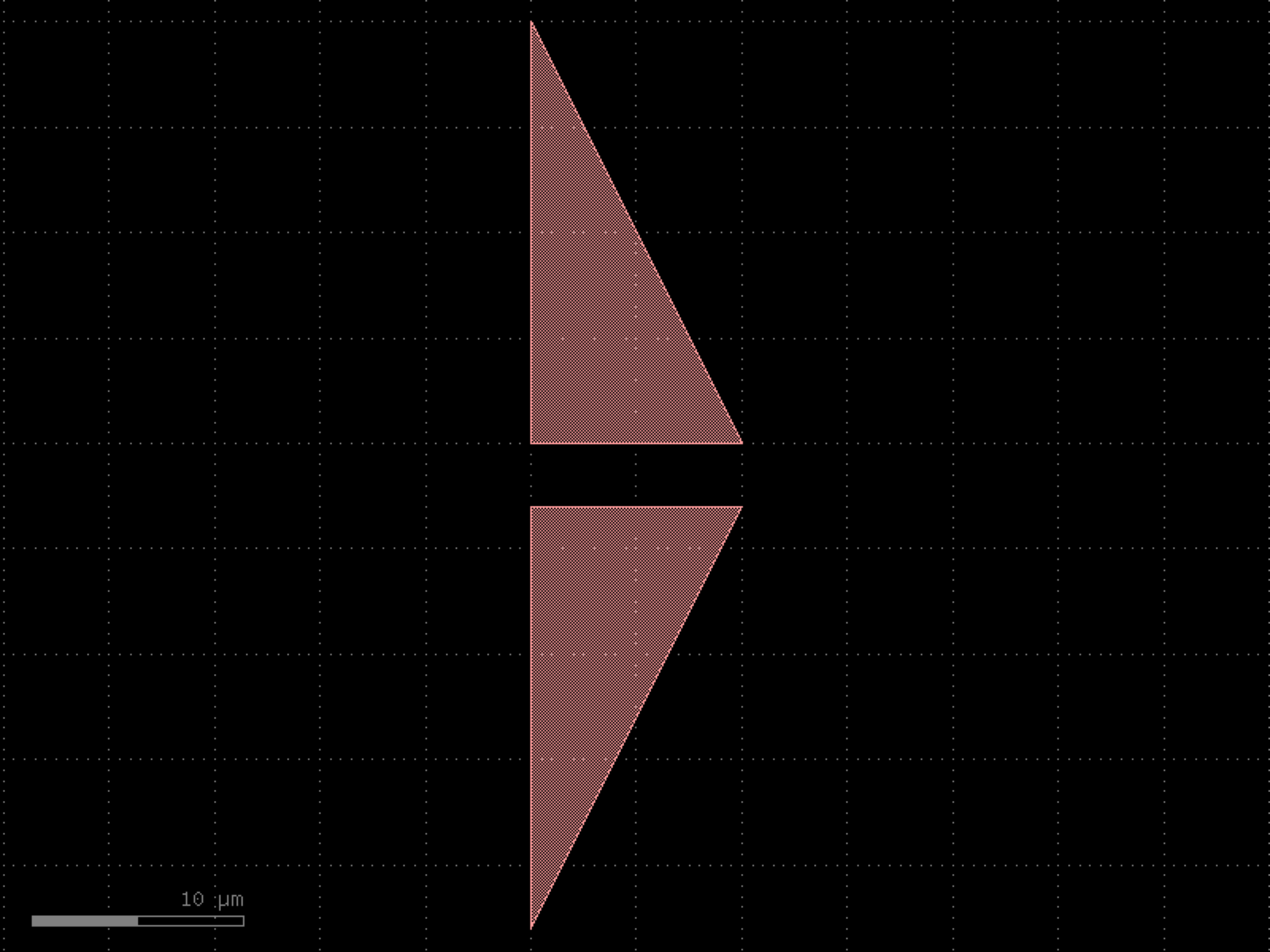

- gdsfactory.components.superconductors.ytron_round(rho=1, arm_lengths=(500, 300), source_length=500, arm_widths=(200, 200), theta=2.5, theta_resolution=10, layer='WG')[source]#
Ytron structure for superconducting nanowires.
McCaughan, A. N., Abebe, N. S., Zhao, Q.-Y. & Berggren, K. K. Using Geometry To Sense Current. Nano Lett. 16, 7626-7631 (2016). http://dx.doi.org/10.1021/acs.nanolett.6b03593
- Parameters:
rho (float) – Radius of curvature of ytron intersection point.
arm_lengths (tuple[float, float]) – Lengths of the left and right arms of the yTron, respectively.
source_length (float) – Length of the source of the yTron.
arm_widths (tuple[float, float]) – Widths of the left and right arms of the yTron, respectively.
theta (float) – Angle between the two yTron arms.
theta_resolution (float) – Angle resolution for curvature of ytron intersection point.
layer (LayerSpec) – Specific layer(s) to put polygon geometry on.
- Returns:
Component containing a yTron geometry.
- Return type:
import gdsfactory as gf
gf.gpdk.PDK.activate()
c = gf.components.ytron_round(rho=1, arm_lengths=(500, 300), source_length=500, arm_widths=(200, 200), theta=2.5, theta_resolution=10, layer='WG').copy()
c.draw_ports()
c.plot()
(Source code, png, hires.png, pdf)
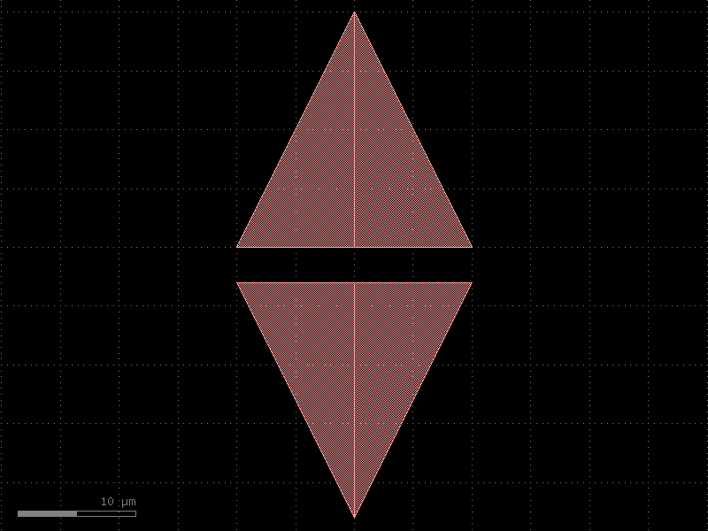
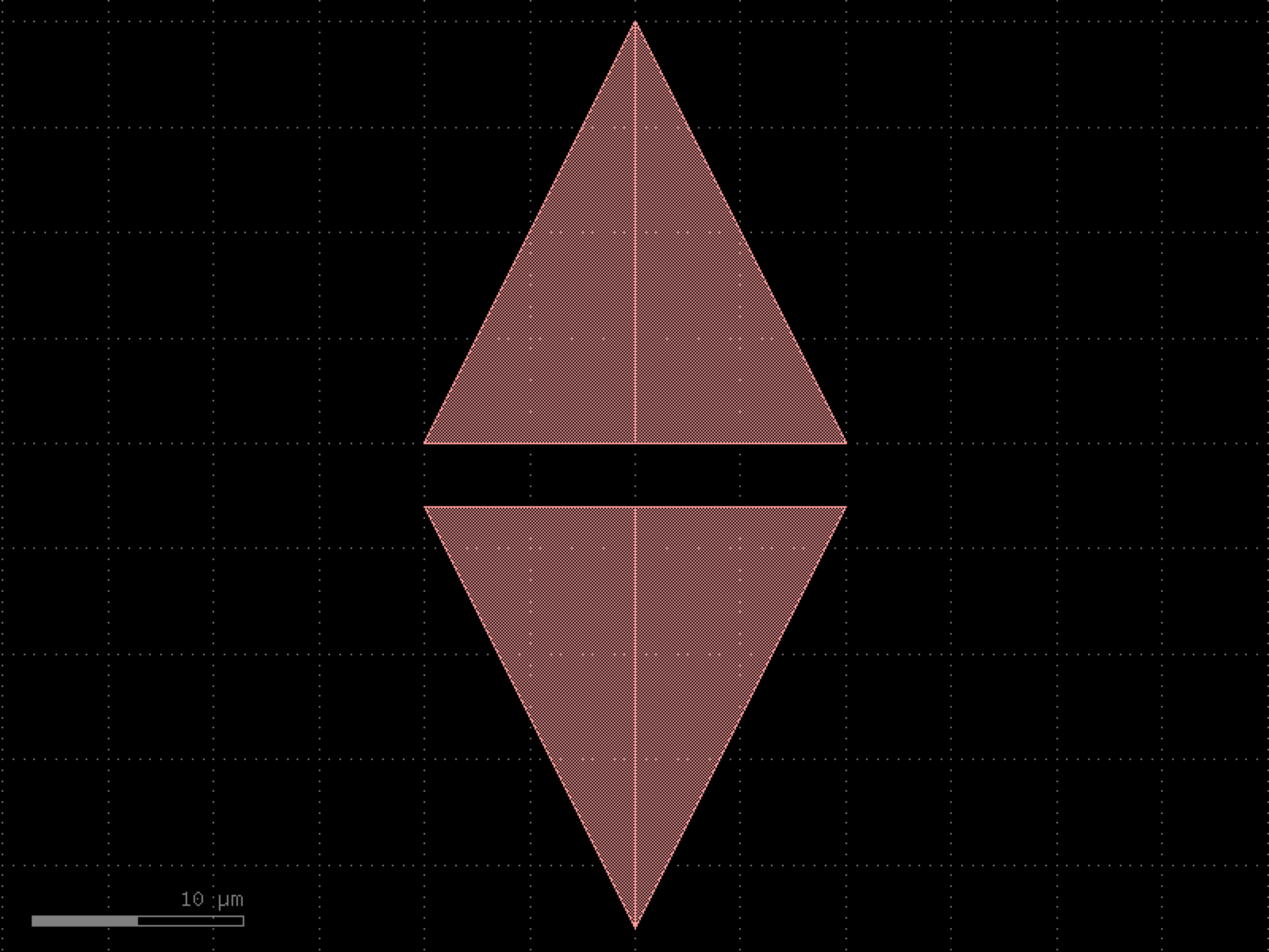

tapers#
- gdsfactory.components.tapers.ramp(length=10.0, width1=5.0, width2=8.0, layer='WG')[source]#
Return a ramp component.
Based on phidl.
- Parameters:
length (float) – Length of the ramp section.
width1 (float) – Width of the start of the ramp section.
width2 (float | None) – Width of the end of the ramp section (defaults to width1).
layer (LayerSpec) – Specific layer to put polygon geometry on.
- Return type:
import gdsfactory as gf
gf.gpdk.PDK.activate()
c = gf.components.ramp(length=10, width1=5, width2=8, layer='WG').copy()
c.draw_ports()
c.plot()
(Source code, png, hires.png, pdf)
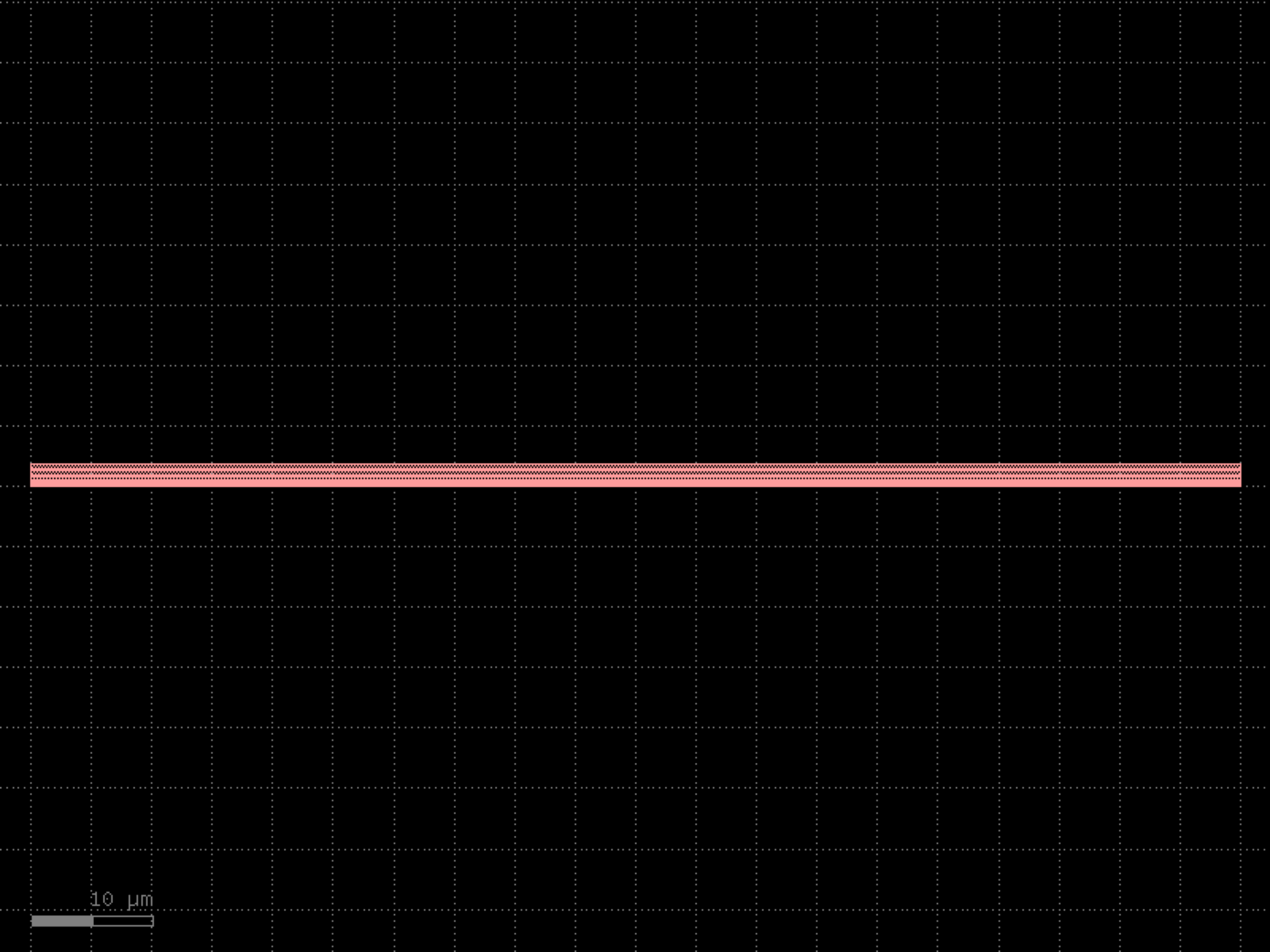

- gdsfactory.components.tapers.taper(length=10.0, width1=0.5, width2=None, layer=None, port=None, with_two_ports=True, cross_section='strip', port_names=('o1', 'o2'), port_types=('optical', 'optical'), with_bbox=True)[source]#
Linear taper, which tapers only the main cross section section.
- Parameters:
length (float) – taper length.
width1 (float) – width of the west/left port.
width2 (float | None) – width of the east/right port. Defaults to width1.
layer (LayerSpec | None) – layer for the taper.
port (Port | None) – can taper from a port instead of defining width1.
with_two_ports (bool) – includes a second port. False for terminator and edge coupler fiber interface.
cross_section (CrossSectionSpec) – specification (CrossSection, string, CrossSectionFactory dict).
port_names (tuple[str, str]) – input and output port names. Second name only used if with_two_ports.
port_types (tuple[str, str]) – input and output port types. Second type only used if with_two_ports.
with_bbox (bool) – box in bbox_layers and bbox_offsets to avoid DRC sharp edges.
- Return type:
import gdsfactory as gf
gf.gpdk.PDK.activate()
c = gf.components.taper(length=10, width1=0.5, with_two_ports=True, cross_section='strip', port_names=('o1', 'o2'), port_types=('optical', 'optical'), with_bbox=True).copy()
c.draw_ports()
c.plot()
(Source code, png, hires.png, pdf)
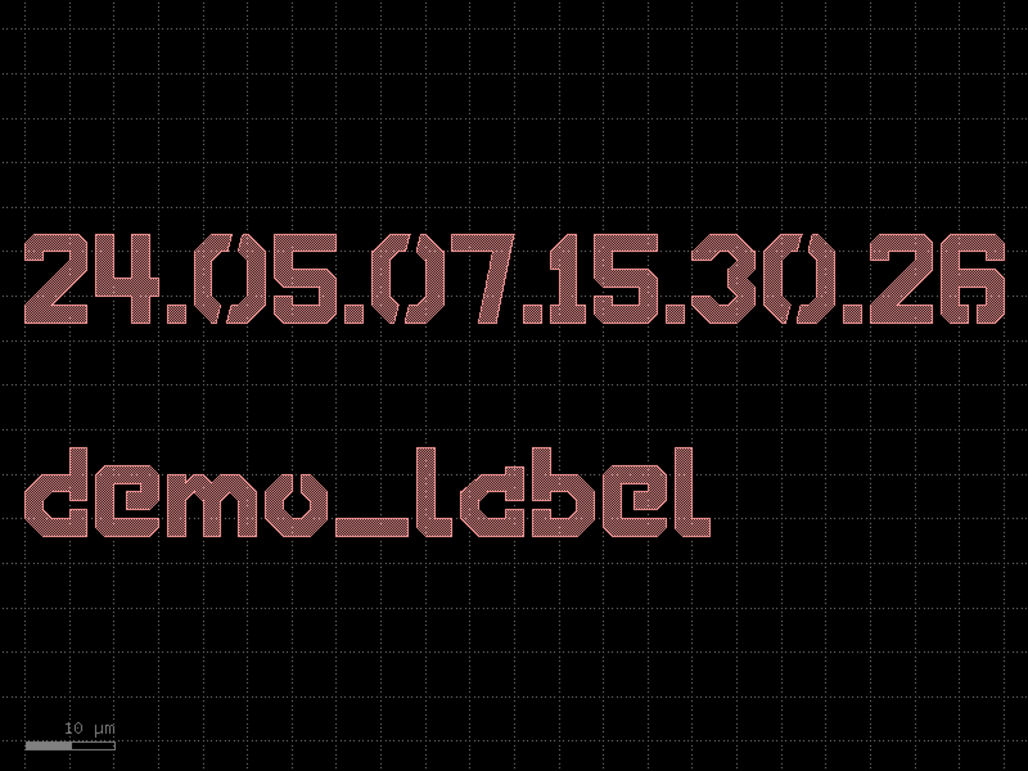
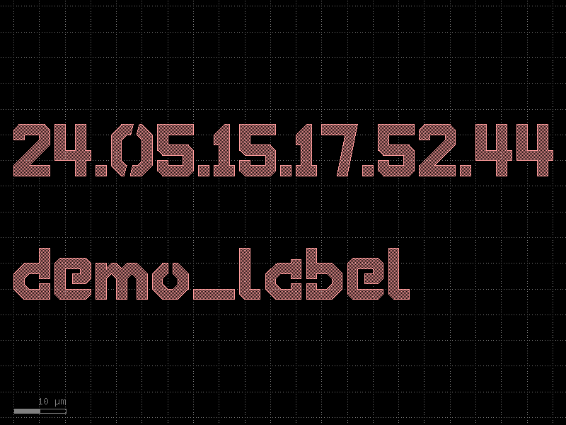
- gdsfactory.components.tapers.taper_0p5_to_3_l36(*, filepath=PosixPath('/home/runner/work/gdsfactory/gdsfactory/gdsfactory/components/tapers/csv_data/taper_strip_0p5_3_36.csv'), cross_section='strip')#
Returns taper from CSV file.
import gdsfactory as gf
gf.gpdk.PDK.activate()
c = gf.components.taper_0p5_to_3_l36(cross_section='strip').copy()
c.draw_ports()
c.plot()
(Source code, png, hires.png, pdf)
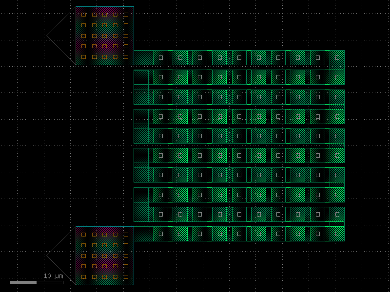
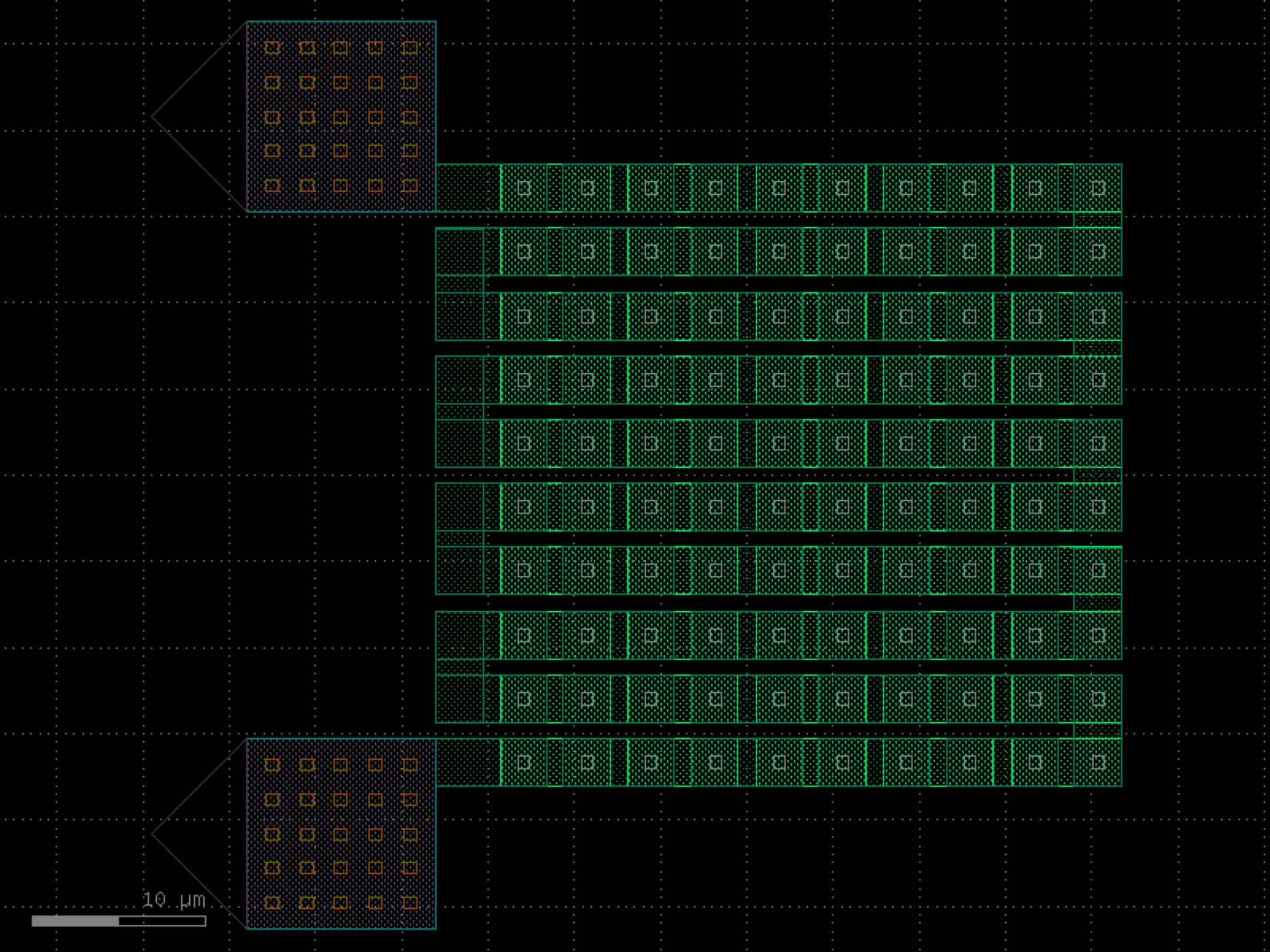

- gdsfactory.components.tapers.taper_adiabatic(width1=0.5, width2=5.0, length=0, neff_w=<function neff_TE1550SOI_220nm>, alpha=1, wavelength=1.55, npoints=200, cross_section='strip', max_length=200)[source]#
Returns a straight adiabatic_taper from an effective index callable.
- Parameters:
width1 (float) – initial width.
width2 (float) – final width.
length (float) – 0 uses the optimized length, and otherwise the optimal shape is compressed/stretched to the specified length.
neff_w (Callable[[float], float]) – a callable that returns the effective index as a function of width - By default, will use a compact model of neff(y) for fundamental 1550 nm TE mode of 220nm-thick core with 3.45 index, fully clad with 1.44 index. Many coefficients are needed to capture the behaviour.
alpha (float) – parameter that scales the rate of width change. - closer to 0 means longer and more adiabatic; - 1 is the intuitive limit beyond which higher order modes are excited; - [2] reports good performance up to 1.4 for fundamental TE in SOI (for multiple core thicknesses)
wavelength (float) – wavelength in um.
npoints (int) – number of points for sampling.
cross_section (CrossSectionSpec) – cross_section specification.
max_length (float) – maximum length for the taper.
- Return type:
References
[1] Burns, W. K., et al. “Optical waveguide parabolic coupling horns.” Appl. Phys. Lett., vol. 30, no. 1, 1 Jan. 1977, pp. 28-30, doi:10.1063/1.89199. [2] Fu, Yunfei, et al. “Efficient adiabatic silicon-on-insulator waveguide taper.” Photonics Res., vol. 2, no. 3, 1 June 2014, pp. A41-A44, doi:10.1364/PRJ.2.000A41. npoints: number of points for sampling
import gdsfactory as gf
gf.gpdk.PDK.activate()
c = gf.components.taper_adiabatic(width1=0.5, width2=5, length=0, alpha=1, wavelength=1.55, npoints=200, cross_section='strip', max_length=200).copy()
c.draw_ports()
c.plot()
(Source code, png, hires.png, pdf)
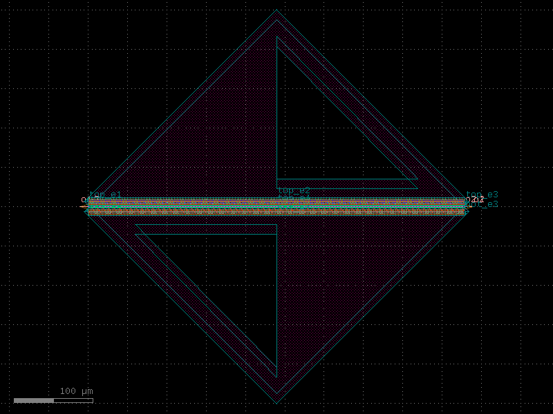
- gdsfactory.components.tapers.taper_cross_section(cross_section1='strip_rib_tip', cross_section2='rib2', length=10, npoints=100, linear=False, width_type='sine', exclude_layers=None)[source]#
Returns taper transition between cross_section1 and cross_section2.
- Parameters:
cross_section1 (CrossSectionSpec) – start cross_section factory.
cross_section2 (CrossSectionSpec) – end cross_section factory.
length (float) – transition length.
npoints (int) – number of points.
linear (bool) – shape of the transition, sine when False.
width_type (str) – shape of the transition ONLY IF linear is False
exclude_layers (LayerSpecs | None) – layers to exclude from the transition. Sections on these layers will be omitted from the component.
- Return type:
_____________________ / _______/______________________ / cross_section1 | cross_section2 ______\_______________________ \ \_____________________
import gdsfactory as gf
gf.gpdk.PDK.activate()
c = gf.components.taper_cross_section(cross_section1='strip_rib_tip', cross_section2='rib2', length=10, npoints=100, linear=False, width_type='sine').copy()
c.draw_ports()
c.plot()
(Source code, png, hires.png, pdf)
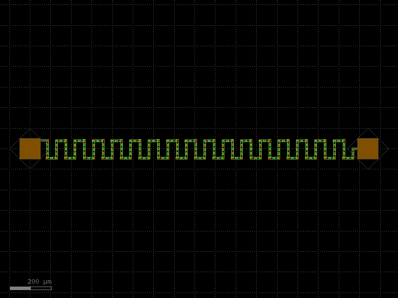
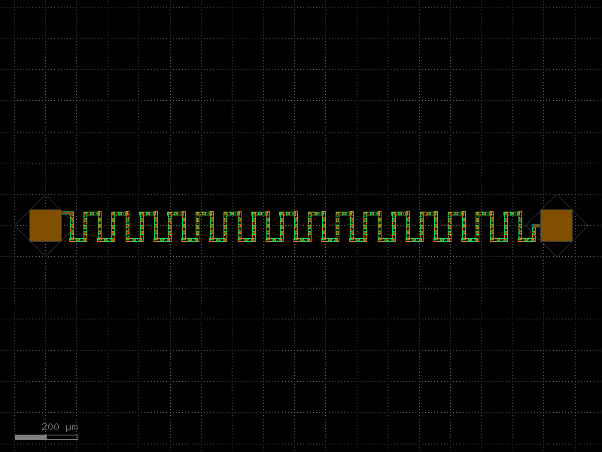

- gdsfactory.components.tapers.taper_cross_section_linear(cross_section1='strip_rib_tip', cross_section2='rib2', length=10, *, npoints=2, linear=True, width_type='sine', exclude_layers=None)#
Returns taper transition between cross_section1 and cross_section2.
- Parameters:
cross_section1 (CrossSectionSpec) – start cross_section factory.
cross_section2 (CrossSectionSpec) – end cross_section factory.
length (float) – transition length.
npoints (int) – number of points.
linear (bool) – shape of the transition, sine when False.
width_type (str) – shape of the transition ONLY IF linear is False
exclude_layers (LayerSpecs | None) – layers to exclude from the transition. Sections on these layers will be omitted from the component.
- Return type:
_____________________ / _______/______________________ / cross_section1 | cross_section2 ______\_______________________ \ \_____________________
import gdsfactory as gf
gf.gpdk.PDK.activate()
c = gf.components.taper_cross_section_linear(cross_section1='strip_rib_tip', cross_section2='rib2', length=10, npoints=2, linear=True, width_type='sine').copy()
c.draw_ports()
c.plot()
(Source code, png, hires.png, pdf)
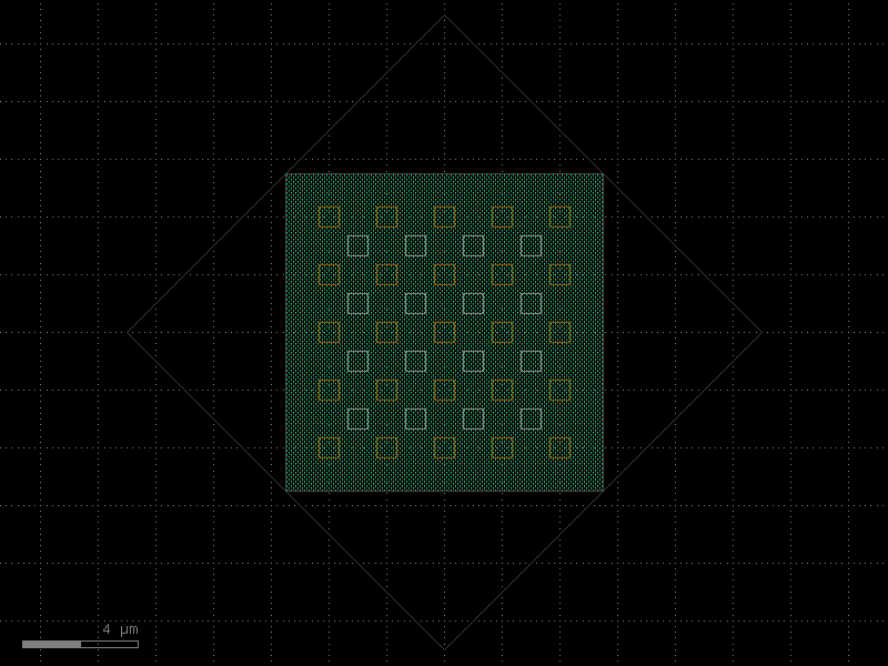
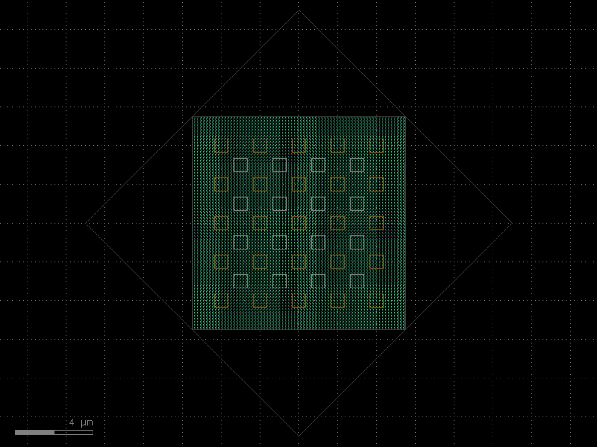

- gdsfactory.components.tapers.taper_cross_section_parabolic(cross_section1='strip_rib_tip', cross_section2='rib2', length=10, *, npoints=101, linear=False, width_type='parabolic', exclude_layers=None)#
Returns taper transition between cross_section1 and cross_section2.
- Parameters:
cross_section1 (CrossSectionSpec) – start cross_section factory.
cross_section2 (CrossSectionSpec) – end cross_section factory.
length (float) – transition length.
npoints (int) – number of points.
linear (bool) – shape of the transition, sine when False.
width_type (str) – shape of the transition ONLY IF linear is False
exclude_layers (LayerSpecs | None) – layers to exclude from the transition. Sections on these layers will be omitted from the component.
- Return type:
_____________________ / _______/______________________ / cross_section1 | cross_section2 ______\_______________________ \ \_____________________
import gdsfactory as gf
gf.gpdk.PDK.activate()
c = gf.components.taper_cross_section_parabolic(cross_section1='strip_rib_tip', cross_section2='rib2', length=10, npoints=101, linear=False, width_type='parabolic').copy()
c.draw_ports()
c.plot()
(Source code, png, hires.png, pdf)
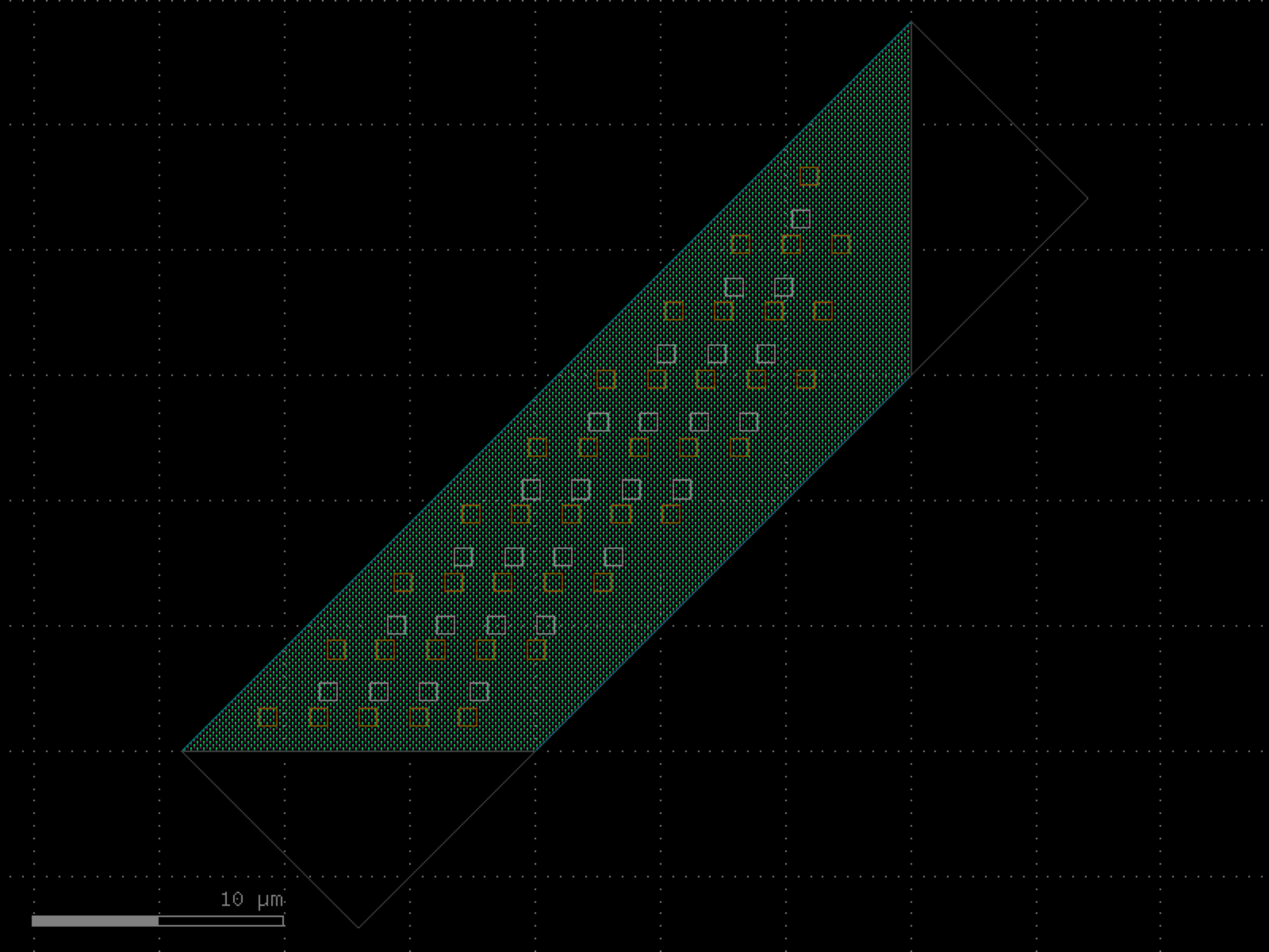
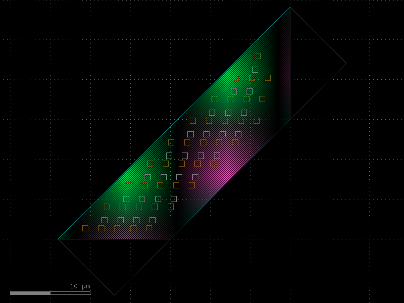
- gdsfactory.components.tapers.taper_cross_section_sine(cross_section1='strip_rib_tip', cross_section2='rib2', length=10, *, npoints=101, linear=False, width_type='sine', exclude_layers=None)#
Returns taper transition between cross_section1 and cross_section2.
- Parameters:
cross_section1 (CrossSectionSpec) – start cross_section factory.
cross_section2 (CrossSectionSpec) – end cross_section factory.
length (float) – transition length.
npoints (int) – number of points.
linear (bool) – shape of the transition, sine when False.
width_type (str) – shape of the transition ONLY IF linear is False
exclude_layers (LayerSpecs | None) – layers to exclude from the transition. Sections on these layers will be omitted from the component.
- Return type:
_____________________ / _______/______________________ / cross_section1 | cross_section2 ______\_______________________ \ \_____________________
import gdsfactory as gf
gf.gpdk.PDK.activate()
c = gf.components.taper_cross_section_sine(cross_section1='strip_rib_tip', cross_section2='rib2', length=10, npoints=101, linear=False, width_type='sine').copy()
c.draw_ports()
c.plot()
(Source code, png, hires.png, pdf)
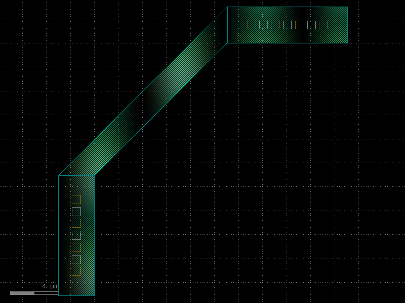
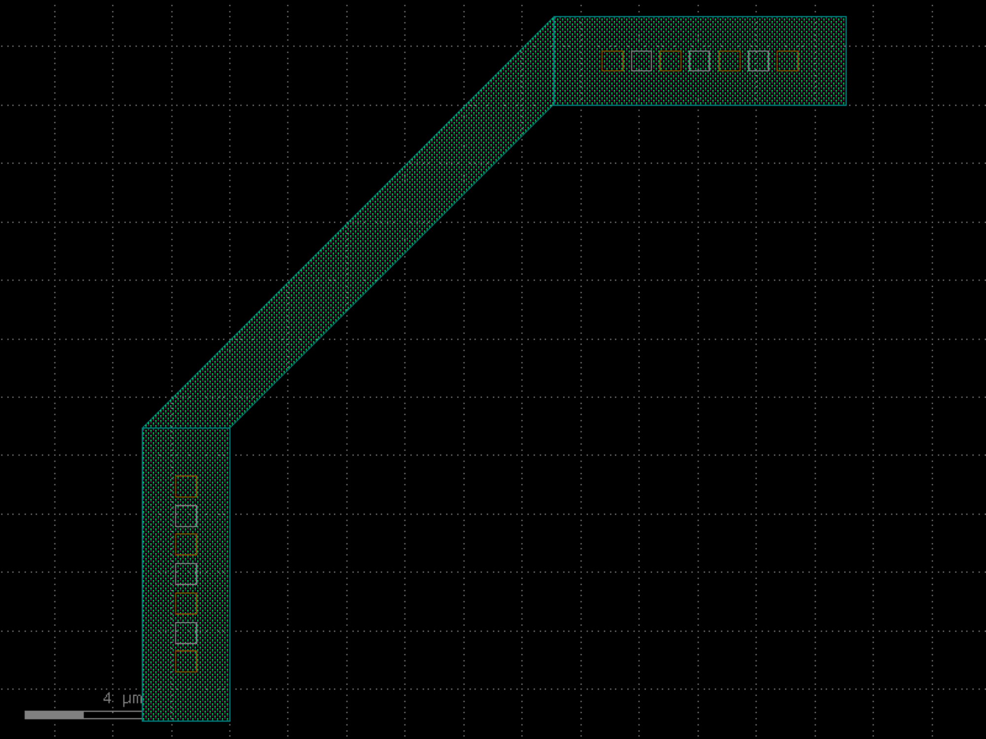

- gdsfactory.components.tapers.taper_electrical(length=10.0, width1=0.5, width2=None, layer=None, port=None, with_two_ports=True, *, cross_section='metal_routing', port_names=('e1', 'e2'), port_types=('electrical', 'electrical'), with_bbox=True)#
Linear taper, which tapers only the main cross section section.
- Parameters:
length (float) – taper length.
width1 (float) – width of the west/left port.
width2 (float | None) – width of the east/right port. Defaults to width1.
layer (LayerSpec | None) – layer for the taper.
port (Port | None) – can taper from a port instead of defining width1.
with_two_ports (bool) – includes a second port. False for terminator and edge coupler fiber interface.
cross_section (CrossSectionSpec) – specification (CrossSection, string, CrossSectionFactory dict).
port_names (tuple[str, str]) – input and output port names. Second name only used if with_two_ports.
port_types (tuple[str, str]) – input and output port types. Second type only used if with_two_ports.
with_bbox (bool) – box in bbox_layers and bbox_offsets to avoid DRC sharp edges.
- Return type:
import gdsfactory as gf
gf.gpdk.PDK.activate()
c = gf.components.taper_electrical(length=10, width1=0.5, with_two_ports=True, cross_section='metal_routing', port_names=('e1', 'e2'), port_types=('electrical', 'electrical'), with_bbox=True).copy()
c.draw_ports()
c.plot()
(Source code, png, hires.png, pdf)
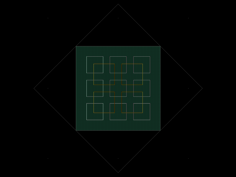
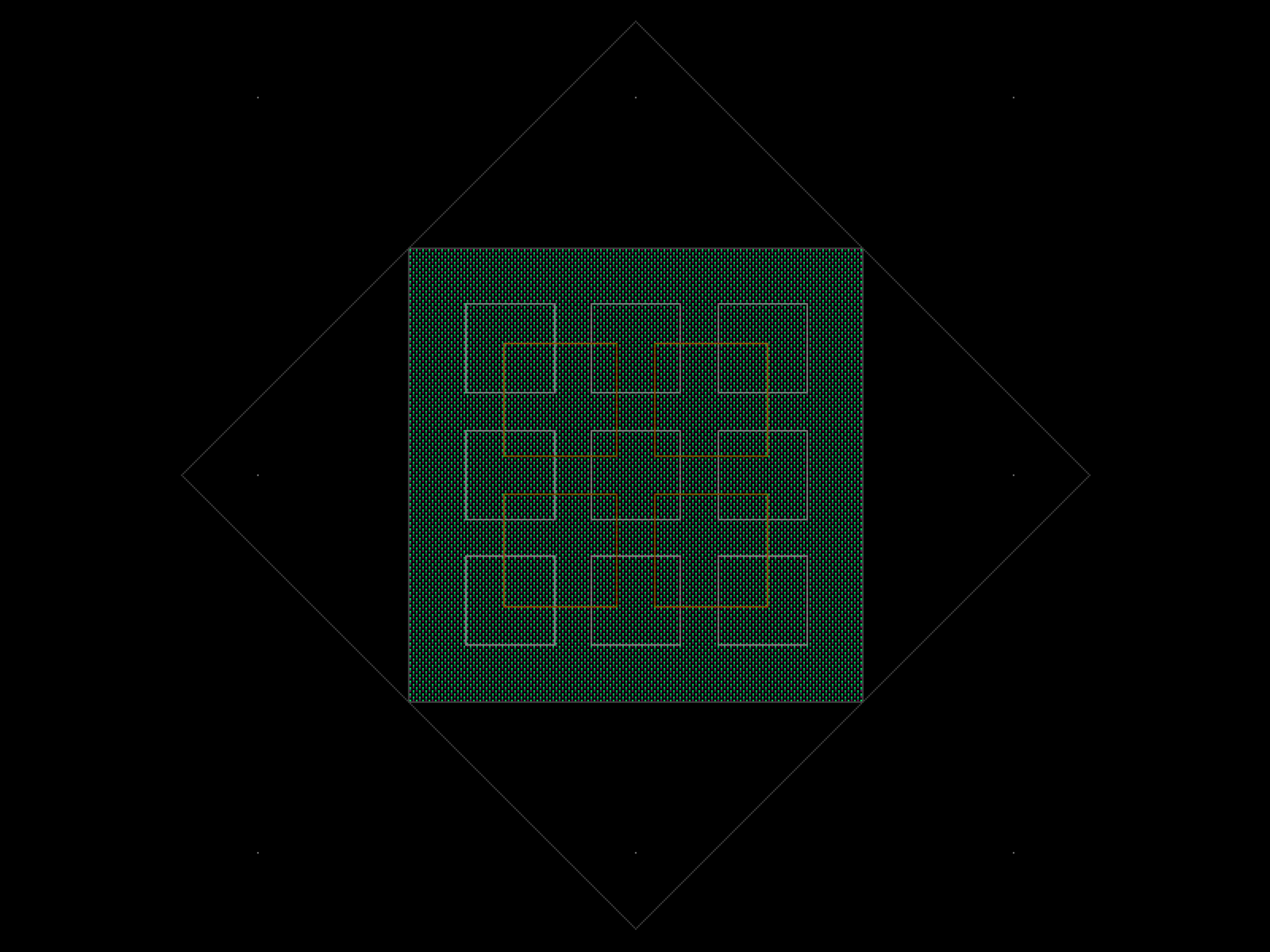

- gdsfactory.components.tapers.taper_from_csv(filepath=PosixPath('/home/runner/work/gdsfactory/gdsfactory/gdsfactory/components/tapers/csv_data/taper_strip_0p5_3_36.csv'), cross_section='strip')[source]#
Returns taper from CSV file.
- Parameters:
filepath (Path) – for CSV file.
cross_section (CrossSectionSpec) – specification (CrossSection, string, CrossSectionFactory dict).
- Return type:
import gdsfactory as gf
gf.gpdk.PDK.activate()
c = gf.components.taper_from_csv(cross_section='strip').copy()
c.draw_ports()
c.plot()
(Source code, png, hires.png, pdf)
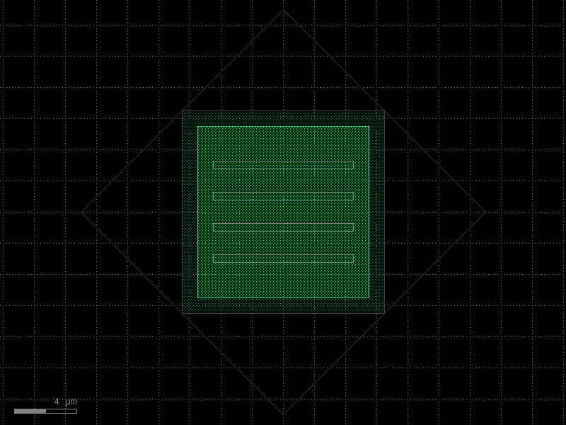
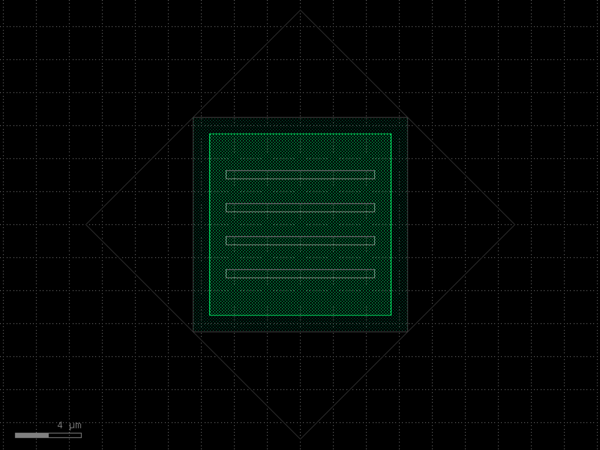

- gdsfactory.components.tapers.taper_hecken(length=200, B=4.0091, dielectric_thickness=0.25, eps_r=2, Lk_per_sq=2.5e-10, Z1=50, Z2=100, width1=None, width2=None, num_pts=100, layer='WG')[source]#
Creates a Hecken-tapered microstrip.
- Parameters:
length (float) – Length of the microstrip.
B (float) – Controls the intensity of the taper.
dielectric_thickness (float) – Thickness of the substrate.
eps_r (float) – Dielectric constant of the substrate.
Lk_per_sq (float) – Kinetic inductance per square of the microstrip.
Z1 (float | None) – Impedance of the left side region of the microstrip.
Z2 (float | None) – Impedance of the right side region of the microstrip.
width1 (float | None) – Width of the left side of the microstrip.
width2 (float | None) – Width of the right side of the microstrip.
num_pts (int) – Number of points comprising the curve of the entire microstrip.
layer (LayerSpec) – Specific layer(s) to put polygon geometry on.
- Returns:
Component containing a Hecken-tapered microstrip.
- Return type:
import gdsfactory as gf
gf.gpdk.PDK.activate()
c = gf.components.taper_hecken(length=200, B=4.009, dielectric_thickness=0.25, eps_r=2, Lk_per_sq=0.0, Z1=50, Z2=100, num_pts=100, layer='WG').copy()
c.draw_ports()
c.plot()
(Source code, png, hires.png, pdf)
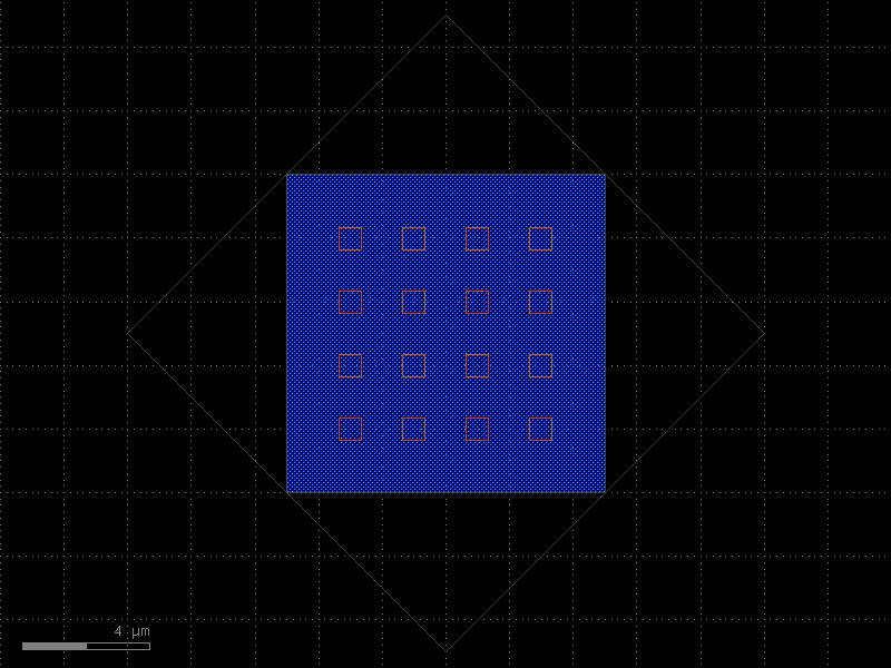
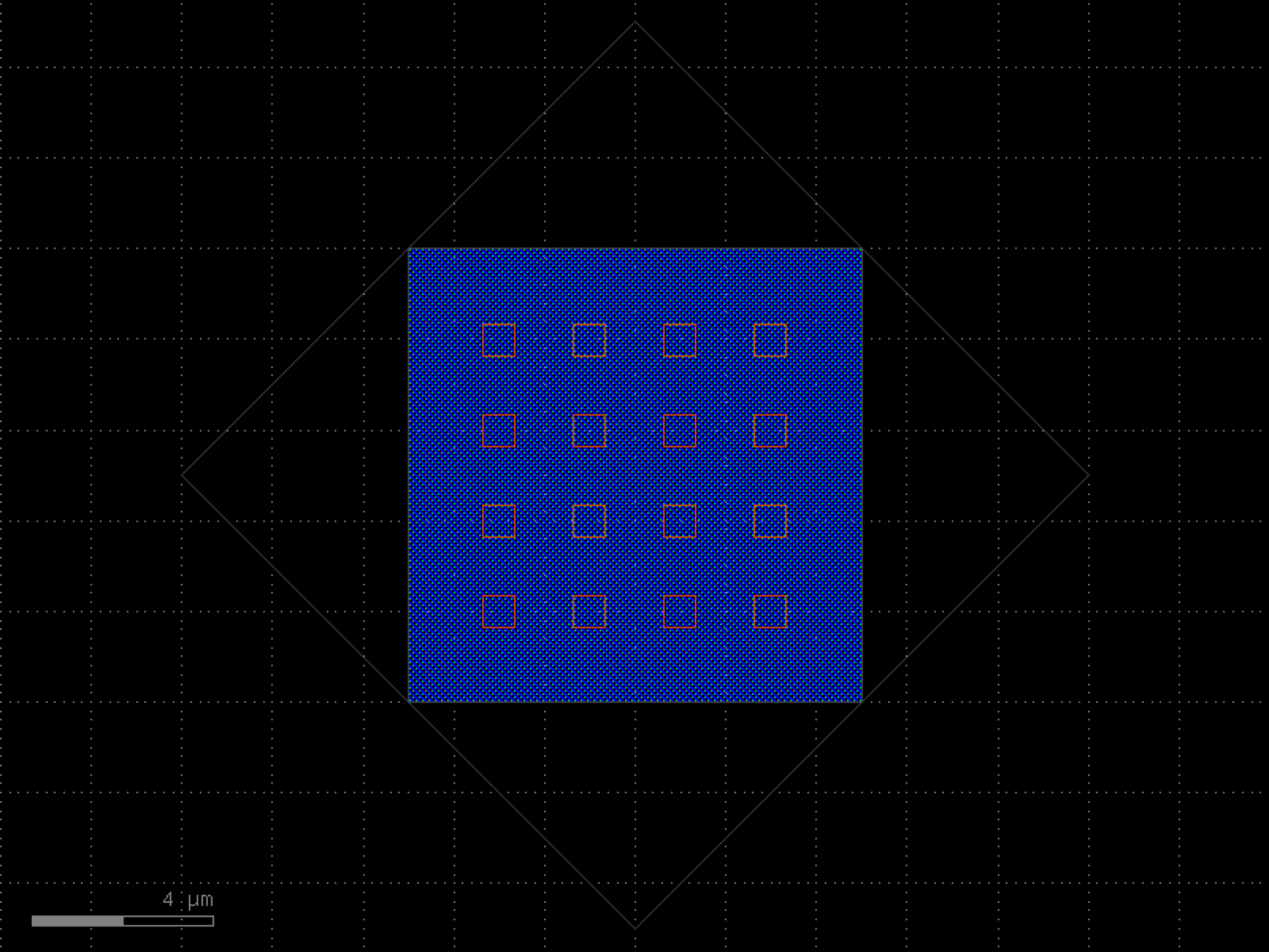

- gdsfactory.components.tapers.taper_meander(x_taper=None, w_taper=None, meander_length=1000, spacing_factor=3, min_spacing=0.5, layer='WG')[source]#
Create a meander from arrays of x-positions and widths.
Typically used for creating meandered tapers.
- Parameters:
x_taper (tuple[float, ...] | None) – The x-coordinates of the data points, must be increasing.
w_taper (tuple[float, ...] | None) – The widths at each x-coordinate, same length as x_taper.
meander_length (float) – Length of each section of the meander.
spacing_factor (float) – Multiplicative spacing factor between adjacent meanders.
min_spacing (float) – Minimum spacing between adjacent meanders.
layer (LayerSpec) – Specific layer(s) to put polygon geometry on.
- Returns:
Component containing the meandered taper.
- Return type:
import gdsfactory as gf
gf.gpdk.PDK.activate()
c = gf.components.taper_meander(meander_length=1000, spacing_factor=3, min_spacing=0.5, layer='WG').copy()
c.draw_ports()
c.plot()
(Source code, png, hires.png, pdf)
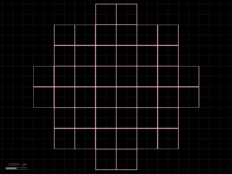

- gdsfactory.components.tapers.taper_nc_sc(width1=1, width2=0.5, length=20, layer_wg='WG', layer_nitride='WGN', width_tip_nitride=0.15, width_tip_silicon=0.15, cross_section='strip')[source]#
Taper from nitride to strip.
- Parameters:
width1 (float) – nitride width.
width2 (float) – silicon width.
length (float) – taper length.
layer_wg (LayerSpec) – nitride layer.
layer_nitride (LayerSpec) – strip layer.
width_tip_nitride (float) – tip width for nitride.
width_tip_silicon (float) – tip width for strip.
cross_section (CrossSectionSpec) – cross_section specification.
- Return type:
import gdsfactory as gf
gf.gpdk.PDK.activate()
c = gf.components.taper_nc_sc(width1=1, width2=0.5, length=20, layer_wg='WG', layer_nitride='WGN', width_tip_nitride=0.15, width_tip_silicon=0.15, cross_section='strip').copy()
c.draw_ports()
c.plot()
(Source code, png, hires.png, pdf)
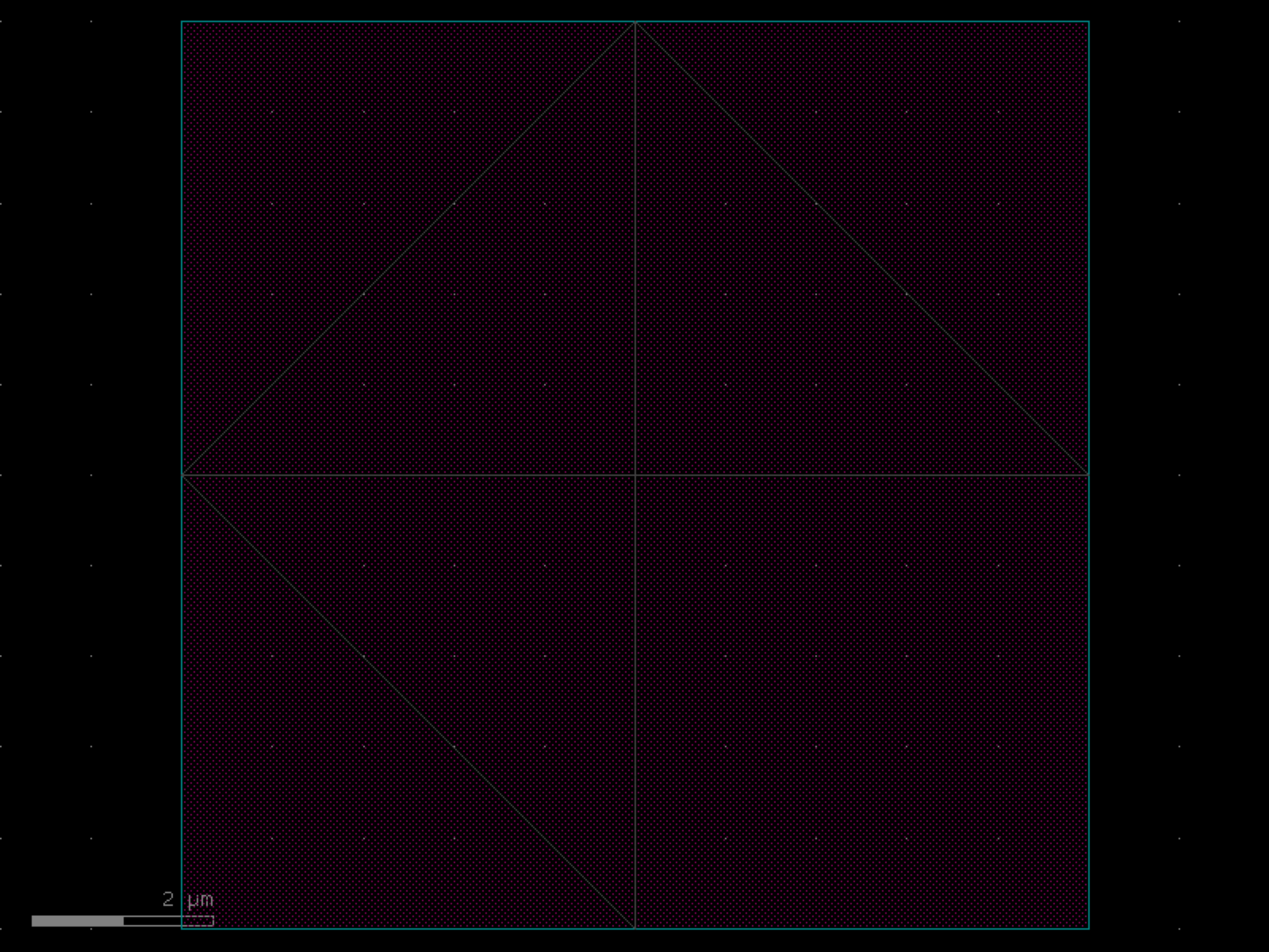
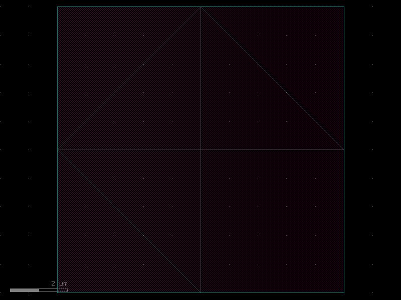
- gdsfactory.components.tapers.taper_parabolic(length=20, width1=0.5, width2=5.0, exp=0.5, npoints=100, layer='WG')[source]#
Returns a parabolic_taper.
- Parameters:
length (float) – in um.
width1 (float) – in um.
width2 (float) – in um.
exp (float) – exponent.
npoints (int) – number of points.
layer (LayerSpec) – layer spec.
- Return type:
import gdsfactory as gf
gf.gpdk.PDK.activate()
c = gf.components.taper_parabolic(length=20, width1=0.5, width2=5, exp=0.5, npoints=100, layer='WG').copy()
c.draw_ports()
c.plot()
(Source code, png, hires.png, pdf)
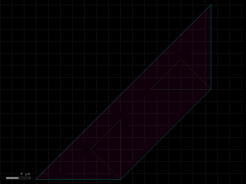

- gdsfactory.components.tapers.taper_sc_nc(width1=0.5, width2=1, length=20, layer_wg='WG', layer_nitride='WGN', width_tip_nitride=0.15, width_tip_silicon=0.15, cross_section='strip')[source]#
Taper from strip to nitride.
- Parameters:
width1 (float) – strip width.
width2 (float) – nitride width.
length (float) – taper length.
layer_wg (LayerSpec) – strip layer.
layer_nitride (LayerSpec) – nitride layer.
width_tip_nitride (float) – tip width for nitride.
width_tip_silicon (float) – tip width for strip.
cross_section (CrossSectionSpec) – cross_section specification.
- Return type:
import gdsfactory as gf
gf.gpdk.PDK.activate()
c = gf.components.taper_sc_nc(width1=0.5, width2=1, length=20, layer_wg='WG', layer_nitride='WGN', width_tip_nitride=0.15, width_tip_silicon=0.15, cross_section='strip').copy()
c.draw_ports()
c.plot()
(Source code, png, hires.png, pdf)
- gdsfactory.components.tapers.taper_strip_to_ridge(length=10.0, width1=0.5, width2=0.5, w_slab1=0.15, w_slab2=6.0, layer_wg='WG', layer_slab='SLAB90', cross_section='strip', use_slab_port=False, slab_port_layer=None)[source]#
Linear taper from strip to rib.
- Parameters:
length (float) – taper length (um).
width1 (float) – in um.
width2 (float) – in um.
w_slab1 (float) – slab width in um.
w_slab2 (float) – slab width in um.
layer_wg (LayerSpec) – for input waveguide.
layer_slab (LayerSpec) – for output waveguide with slab.
cross_section (CrossSectionSpec) – for input waveguide.
use_slab_port (bool) – if True adds a second port for the slab.
slab_port_layer (LayerSpec | None) – if specified, overrides the layer for the slab port.
- Return type:
__________________________ / | _______/____________|______________ / | width1 |w_slab1 | w_slab2 width2 ______\_____________|______________ \ | \__________________________
import gdsfactory as gf
gf.gpdk.PDK.activate()
c = gf.components.taper_strip_to_ridge(length=10, width1=0.5, width2=0.5, w_slab1=0.15, w_slab2=6, layer_wg='WG', layer_slab='SLAB90', cross_section='strip', use_slab_port=False).copy()
c.draw_ports()
c.plot()
(Source code, png, hires.png, pdf)
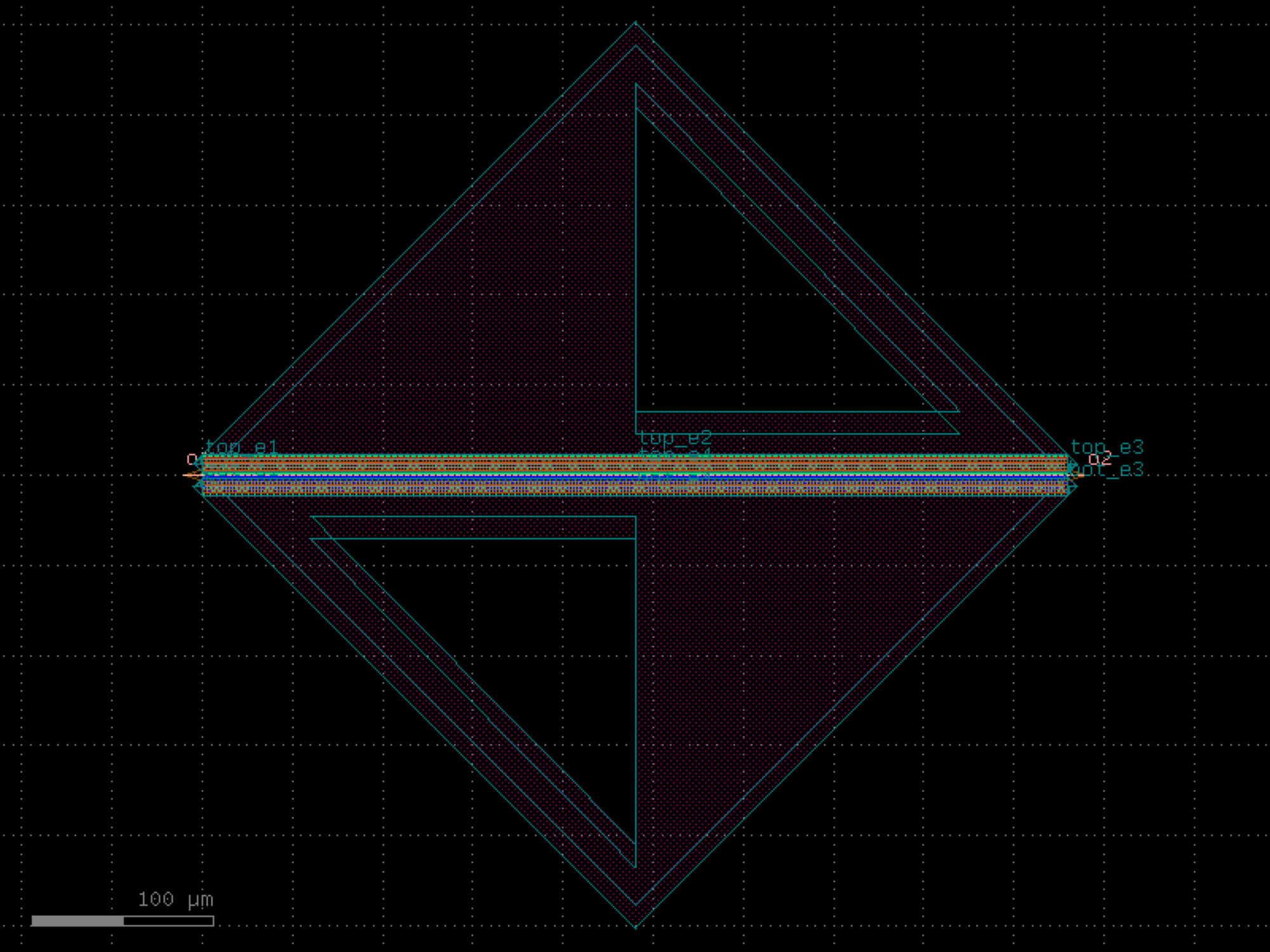

- gdsfactory.components.tapers.taper_strip_to_ridge_trenches(length=10.0, width=0.5, slab_offset=3.0, trench_width=2.0, trench_layer='DEEP_ETCH', layer_wg='WG', trench_offset=0.1)[source]#
Defines taper using trenches to define the etch.
- Parameters:
length (float) – in um.
width (float) – in um.
slab_offset (float) – in um.
trench_width (float) – in um.
trench_layer (LayerSpec) – trench layer.
layer_wg (LayerSpec) – waveguide layer.
trench_offset (float) – after waveguide in um.
- Return type:
import gdsfactory as gf
gf.gpdk.PDK.activate()
c = gf.components.taper_strip_to_ridge_trenches(length=10, width=0.5, slab_offset=3, trench_width=2, trench_layer='DEEP_ETCH', layer_wg='WG', trench_offset=0.1).copy()
c.draw_ports()
c.plot()
(Source code, png, hires.png, pdf)

- gdsfactory.components.tapers.taper_strip_to_slab150(length=10.0, width1=0.5, width2=0.5, w_slab1=0.15, w_slab2=6.0, layer_wg='WG', *, layer_slab='SLAB150', cross_section='strip', use_slab_port=False, slab_port_layer=None)#
Linear taper from strip to rib.
- Parameters:
length (float) – taper length (um).
width1 (float) – in um.
width2 (float) – in um.
w_slab1 (float) – slab width in um.
w_slab2 (float) – slab width in um.
layer_wg (LayerSpec) – for input waveguide.
layer_slab (LayerSpec) – for output waveguide with slab.
cross_section (CrossSectionSpec) – for input waveguide.
use_slab_port (bool) – if True adds a second port for the slab.
slab_port_layer (LayerSpec | None) – if specified, overrides the layer for the slab port.
- Return type:
__________________________ / | _______/____________|______________ / | width1 |w_slab1 | w_slab2 width2 ______\_____________|______________ \ | \__________________________
import gdsfactory as gf
gf.gpdk.PDK.activate()
c = gf.components.taper_strip_to_slab150(length=10, width1=0.5, width2=0.5, w_slab1=0.15, w_slab2=6, layer_wg='WG', layer_slab='SLAB150', cross_section='strip', use_slab_port=False).copy()
c.draw_ports()
c.plot()
(Source code, png, hires.png, pdf)
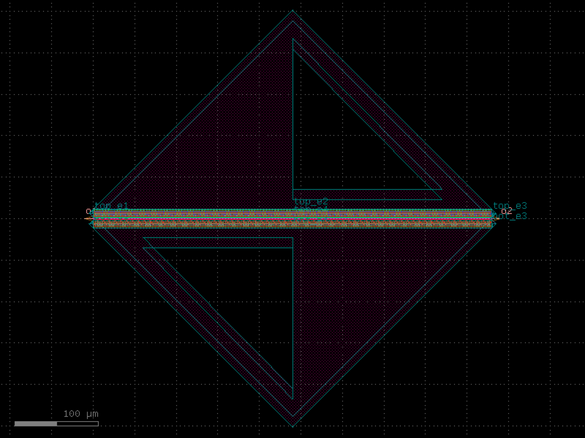

- gdsfactory.components.tapers.taper_w10_l100(*, filepath=PosixPath('/home/runner/work/gdsfactory/gdsfactory/gdsfactory/components/tapers/csv_data/taper_strip_0p5_10_100.csv'), cross_section='strip')#
Returns taper from CSV file.
import gdsfactory as gf
gf.gpdk.PDK.activate()
c = gf.components.taper_w10_l100(cross_section='strip').copy()
c.draw_ports()
c.plot()
(Source code, png, hires.png, pdf)

- gdsfactory.components.tapers.taper_w10_l150(*, filepath=PosixPath('/home/runner/work/gdsfactory/gdsfactory/gdsfactory/components/tapers/csv_data/taper_strip_0p5_10_150.csv'), cross_section='strip')#
Returns taper from CSV file.
import gdsfactory as gf
gf.gpdk.PDK.activate()
c = gf.components.taper_w10_l150(cross_section='strip').copy()
c.draw_ports()
c.plot()
(Source code, png, hires.png, pdf)

- gdsfactory.components.tapers.taper_w10_l200(*, filepath=PosixPath('/home/runner/work/gdsfactory/gdsfactory/gdsfactory/components/tapers/csv_data/taper_strip_0p5_10_200.csv'), cross_section='strip')#
Returns taper from CSV file.
import gdsfactory as gf
gf.gpdk.PDK.activate()
c = gf.components.taper_w10_l200(cross_section='strip').copy()
c.draw_ports()
c.plot()
(Source code, png, hires.png, pdf)

- gdsfactory.components.tapers.taper_w11_l200(*, filepath=PosixPath('/home/runner/work/gdsfactory/gdsfactory/gdsfactory/components/tapers/csv_data/taper_strip_0p5_11_200.csv'), cross_section='strip')#
Returns taper from CSV file.
import gdsfactory as gf
gf.gpdk.PDK.activate()
c = gf.components.taper_w11_l200(cross_section='strip').copy()
c.draw_ports()
c.plot()
(Source code, png, hires.png, pdf)

- gdsfactory.components.tapers.taper_w12_l200(*, filepath=PosixPath('/home/runner/work/gdsfactory/gdsfactory/gdsfactory/components/tapers/csv_data/taper_strip_0p5_12_200.csv'), cross_section='strip')#
Returns taper from CSV file.
import gdsfactory as gf
gf.gpdk.PDK.activate()
c = gf.components.taper_w12_l200(cross_section='strip').copy()
c.draw_ports()
c.plot()
(Source code, png, hires.png, pdf)
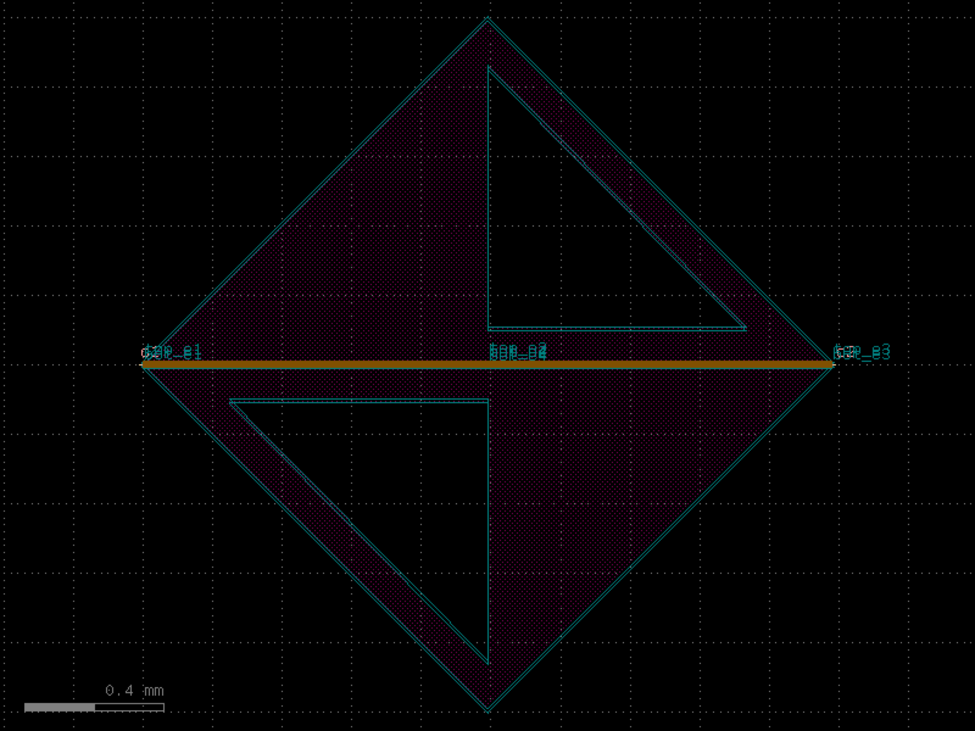

texts#
- gdsfactory.components.texts.pixel_array(pixels='\n XXX\nX X\nXXXXX\nX X\nX X\n\n', pixel_size=10.0, layer='M1')[source]#
Returns a pixel component from a string representing the pixels.
- Parameters:
pixels (str) – string representing the pixels
pixel_size (float) – width/height for each pixel
layer (LayerSpec) – layer for each pixel
- Return type:
import gdsfactory as gf
gf.gpdk.PDK.activate()
c = gf.components.pixel_array(pixels='\n XXX\nX X\nXXXXX\nX X\nX X\n\n', pixel_size=10, layer='M1').copy()
c.draw_ports()
c.plot()
(Source code, png, hires.png, pdf)
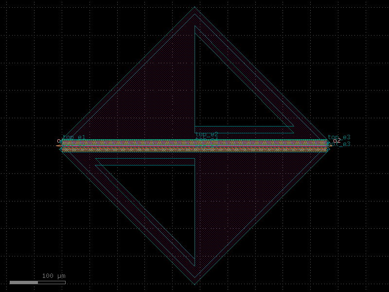

- gdsfactory.components.texts.text(text='abcd', size=10.0, position=(0, 0), justify='left', layer='WG')[source]#
Text shapes.
- Parameters:
text (str) – string.
size (float) – in um of each character.
position (tuple[float, float]) – x, y position.
justify (str) – left, right, center.
layer (LayerSpec) – for the text.
- Return type:
import gdsfactory as gf
gf.gpdk.PDK.activate()
c = gf.components.text(text='abcd', size=10, position=(0, 0), justify='left', layer='WG').copy()
c.draw_ports()
c.plot()
(Source code, png, hires.png, pdf)

- gdsfactory.components.texts.text_freetype(text='a', size=10, justify='left', font=PosixPath('/home/runner/work/gdsfactory/gdsfactory/gdsfactory/components/texts/fonts/OCR-A.ttf'), layer='WG', layers=None)[source]#
Returns text Component.
- Parameters:
text (str) – string.
size (int) – in um.
justify (str) – left, right, center.
font (PathType) – Font face to use. Default DEPLOF does not require additional libraries, otherwise freetype load fonts. You can choose font by name (e.g. “Times New Roman”), or by file OTF or TTF filepath.
layer (LayerSpec) – list of layers to use for the text.
layers (LayerSpecs | None) – list of layers to use for the text.
- Return type:
import gdsfactory as gf
gf.gpdk.PDK.activate()
c = gf.components.text_freetype(text='a', size=10, justify='left', layer='WG').copy()
c.draw_ports()
c.plot()
(Source code, png, hires.png, pdf)

- gdsfactory.components.texts.text_klayout(text='a', layer='WG', layers=None, bbox_layers=None)[source]#
Returns a text component.
- Parameters:
text (str) – string.
layer (LayerSpec) – text layer.
layers (LayerSpecs | None) – layers for the text.
bbox_layers (LayerSpecs | None) – layers for the text bounding box.
- Return type:
import gdsfactory as gf
gf.gpdk.PDK.activate()
c = gf.components.text_klayout(text='a', layer='WG').copy()
c.draw_ports()
c.plot()
(Source code, png, hires.png, pdf)

- gdsfactory.components.texts.text_lines(text=('Chip', '01'), size=0.4, layer='WG')[source]#
Returns a Component from a text lines.
- Parameters:
text (tuple[str, ...]) – list of strings.
size (float) – text size.
layer (LayerSpec) – text layer.
- Return type:
import gdsfactory as gf
gf.gpdk.PDK.activate()
c = gf.components.text_lines(text=('Chip', '01'), size=0.4, layer='WG').copy()
c.draw_ports()
c.plot()
(Source code, png, hires.png, pdf)

- gdsfactory.components.texts.text_rectangular(text='abcd', size=10.0, position=(0.0, 0.0), justify='left', layer='WG', layers=None, font=<functools._lru_cache_wrapper object>)[source]#
Pixel based font, guaranteed to be manhattan, without acute angles.
- Parameters:
text (str) – string.
size (float) – pixel size in um.
position (tuple[float, float]) – coordinate.
justify (str) – left, right or center.
layer (LayerSpec | None) – for text.
layers (LayerSpecs | None) – optional for duplicating the text.
font (Callable[..., dict[str, str]]) – function that returns dictionary of characters.
- Return type:
import gdsfactory as gf
gf.gpdk.PDK.activate()
c = gf.components.text_rectangular(text='abcd', size=10, position=(0, 0), justify='left', layer='WG').copy()
c.draw_ports()
c.plot()
(Source code, png, hires.png, pdf)

- gdsfactory.components.texts.text_rectangular_multi_layer(text='abcd', layers=('WG', 'M1', 'M2', 'MTOP'), text_factory=<function text_rectangular>, **kwargs)[source]#
Returns rectangular text in different layers.
- Parameters:
text (str) – string of text.
layers (LayerSpecs) – list of layers to replicate the text.
text_factory (ComponentSpec) – function to create the text Components.
kwargs (Any) – keyword arguments for text_factory.
- Keyword Arguments:
size – pixel size.
position – coordinate.
justify – left, right or center.
font – function that returns dictionary of characters.
- Return type:
import gdsfactory as gf
gf.gpdk.PDK.activate()
c = gf.components.text_rectangular_multi_layer(text='abcd', layers=('WG', 'M1', 'M2', 'MTOP')).copy()
c.draw_ports()
c.plot()
(Source code, png, hires.png, pdf)

vias#
- gdsfactory.components.vias.via(size=(0.7, 0.7), enclosure=1.0, layer='VIAC', bbox_layers=None, bbox_offset=0, bbox_offsets=None, pitch=2, column_pitch=None, row_pitch=None)[source]#
Rectangular via.
- Parameters:
size (tuple[float, float]) – in x and y direction.
enclosure (float) – inclusion of via.
layer (LayerSpec) – via layer.
bbox_layers (Sequence[LayerSpec] | None) – layers for the bounding box.
bbox_offset (float) – in um.
bbox_offsets (Sequence[float] | None) – List of offsets for each bbox_layer.
pitch (float) – pitch between vias.
column_pitch (float | None) – Optional pitch between columns of vias. Default is pitch.
row_pitch (float | None) – Optional pitch between rows of vias. Default is pitch.
- Return type:
enclosure _________________________________________ |<---> | | gap[0] size[0] | | <------> <-----> | | ______ ______ | | | | | | | | | | | | size[1] | | |______| |______| | | <-------------> | | pitch | |_______________________________________|
import gdsfactory as gf
gf.gpdk.PDK.activate()
c = gf.components.via(size=(0.7, 0.7), enclosure=1, layer='VIAC', bbox_offset=0, pitch=2).copy()
c.draw_ports()
c.plot()
(Source code, png, hires.png, pdf)

- gdsfactory.components.vias.via_chain(num_vias=100, cols=10, via='via1', contact='via_stack_m2_m3', layers_bot=('M1',), layers_top=('M2',), offsets_top=(0,), offsets_bot=(0,), via_min_enclosure=1.0, min_metal_spacing=1.0, contact_offset=0.0)[source]#
Via chain to extract via resistance.
- Parameters:
num_vias (int) – number of vias.
cols (int) – number of column pairs.
via (ComponentSpec) – via component.
contact (ComponentSpec) – contact component.
layers_bot (LayerSpecs) – list of bottom layers.
layers_top (LayerSpecs) – list of top layers.
offsets_top (tuple[float, ...]) – list of top layer offsets.
offsets_bot (tuple[float, ...]) – list of bottom layer offsets.
via_min_enclosure (float) – via_min_enclosure.
min_metal_spacing (float) – min_metal_spacing.
contact_offset (float) – contact offset.
- Return type:
side view: min_metal_spacing ┌────────────────────────────────────┐ ┌────────────────────────────────────┐ │ layers_top │ │ │ │ │◄───────────► │ │ └─────────────┬─────┬────────────────┘ └───────────────┬─────┬──────────────┘ │ │ via_enclosure │ │ │ │◄───────────────► │ │ │ │ │ │ │ │ │ │ │width│ │ │ ◄─────► │ │ │ │ │ │ ┌─────────────┴─────┴───────────────────────────────────────────────┴─────┴───────────────┐ │ layers_bot │ │ │ └─────────────────────────────────────────────────────────────────────────────────────────┘ ◄─────────────────────────────────────────────────────────────────────────────────────────► 2*e + w + min_metal_spacing + 2*e + w
import gdsfactory as gf
gf.gpdk.PDK.activate()
c = gf.components.via_chain(num_vias=100, cols=10, via='via1', contact='via_stack_m2_m3', layers_bot=('M1',), layers_top=('M2',), offsets_top=(0,), offsets_bot=(0,), via_min_enclosure=1, min_metal_spacing=1, contact_offset=0).copy()
c.draw_ports()
c.plot()
(Source code, png, hires.png, pdf)

- gdsfactory.components.vias.via_circular(radius=0.35, enclosure=1.0, layer='VIAC', pitch=2, column_pitch=None, row_pitch=None, angle_resolution=2.5)[source]#
Circular via.
- Parameters:
radius (float) – in um.
enclosure (float) – inclusion of via in um for the layer above.
layer (LayerSpec) – via layer.
pitch (float | None) – pitch between vias.
column_pitch (float | None) – Optional pitch between columns of vias. Default is pitch.
row_pitch (float | None) – Optional pitch between rows of vias. Default is pitch.
angle_resolution (float) – number of degrees per point.
- Return type:
import gdsfactory as gf
gf.gpdk.PDK.activate()
c = gf.components.via_circular(radius=0.35, enclosure=1, layer='VIAC', pitch=2, angle_resolution=2.5).copy()
c.draw_ports()
c.plot()
(Source code, png, hires.png, pdf)
- gdsfactory.components.vias.via_corner(cross_section=((<function metal2>, (0, 180)), (<function metal3>, (90, 270))), vias=('via1', ), layers_labels=('m2', 'm3'), **kwargs)[source]#
Returns Corner via.
Use in place of wire_corner to route between two layers.
- Parameters:
cross_section (MultiCrossSectionAngleSpec) – list of cross_section, orientation pairs.
vias (tuple[ComponentSpec]) – vias to use to fill the rectangles.
layers_labels (tuple[str, ...]) – Labels to use for each layer.
kwargs (Any) – cross_section settings.
- Return type:
gf.Component
import gdsfactory as gf
gf.gpdk.PDK.activate()
c = gf.components.via_corner(cross_section=(({'function': 'metal2', 'module': 'gdsfactory.cross_section.presets'}, (0, 180)), ({'function': 'metal3', 'module': 'gdsfactory.cross_section.presets'}, (90, 270))), layers_labels=('m2', 'm3')).copy()
c.draw_ports()
c.plot()
- gdsfactory.components.vias.via_stack(size=(11.0, 11.0), layers=('M1', 'M2', 'MTOP'), layer_offsets=None, vias=('via1', 'via2', None), layer_to_port_orientations=None, correct_size=False, slot_horizontal=False, slot_vertical=False, port_orientations=(180, 90, 0, -90))[source]#
Rectangular via array stack.
You can use it to connect different metal layers or metals to silicon. You can use the naming convention via_stack_layerSource_layerDestination contains 4 ports (e1, e2, e3, e4)
also know as Via array http://www.vlsi-expert.com/2017/12/vias.html
- Parameters:
size (Size) – of the layers.
layers (LayerSpecs) – layers on which to draw rectangles.
layer_offsets (Floats | tuple[float | tuple[float, float], ...] | None) – Optional offsets for each layer with respect to size. positive grows, negative shrinks the size. If a tuple, it is the offset in x and y.
vias (Sequence[ComponentSpec | None]) – vias to use to fill the rectangles.
layer_to_port_orientations (dict[LayerSpec, list[int]] | None) – dictionary of layer to port_orientations.
correct_size (bool) – if True, if the specified dimensions are too small it increases them to the minimum possible to fit a via.
slot_horizontal (bool) – if True, then vias are horizontal.
slot_vertical (bool) – if True, then vias are vertical.
port_orientations (Ints | None) – list of port_orientations to add. None does not add ports.
- Return type:
import gdsfactory as gf
gf.gpdk.PDK.activate()
c = gf.components.via_stack(size=(11, 11), layers=('M1', 'M2', 'MTOP'), correct_size=False, slot_horizontal=False, slot_vertical=False, port_orientations=(180, 90, 0, -90)).copy()
c.draw_ports()
c.plot()
(Source code, png, hires.png, pdf)

- gdsfactory.components.vias.via_stack_corner45(width=10, layers=('M1', 'M2', 'MTOP'), layer_offsets=None, vias=('via1', 'via2', None), layer_port=None, correct_size=False)[source]#
Rectangular via array stack at a 45 degree angle.
- Parameters:
width (float) – of the corner45.
layers (Sequence[LayerSpec | None]) – layers on which to draw rectangles.
layer_offsets (Floats | None) – Optional offsets for each layer with respect to size. positive grows, negative shrinks the size.
vias (Sequence[ComponentSpec | None]) – vias to use to fill the rectangles.
layer_port (LayerSpec | None) – if None assumes port is on the last layer.
correct_size (bool) – if True, if the specified dimensions are too small it increases them to the minimum possible to fit a via.
- Return type:
import gdsfactory as gf
gf.gpdk.PDK.activate()
c = gf.components.via_stack_corner45(width=10, layers=('M1', 'M2', 'MTOP'), correct_size=False).copy()
c.draw_ports()
c.plot()
(Source code, png, hires.png, pdf)

- gdsfactory.components.vias.via_stack_corner45_extended(corner='via_stack_corner45', via_stack='via_stack', width=3, length=10)[source]#
Rectangular via array stack at a 45 degree angle.
- Parameters:
corner (ComponentSpec) – corner component.
via_stack (ComponentSpec) – for the via stack.
width (float) – of the corner45.
length (float) – of the straight.
- Return type:
import gdsfactory as gf
gf.gpdk.PDK.activate()
c = gf.components.via_stack_corner45_extended(corner='via_stack_corner45', via_stack='via_stack', width=3, length=10).copy()
c.draw_ports()
c.plot()
(Source code, png, hires.png, pdf)

- gdsfactory.components.vias.via_stack_heater_mtop_mini(*, size=(4, 4), layers=('HEATER', 'M2', 'MTOP'), layer_offsets=None, vias=(None, 'via1', 'via2'), layer_to_port_orientations=None, correct_size=False, slot_horizontal=False, slot_vertical=False, port_orientations=(180, 90, 0, -90))#
Rectangular via array stack.
You can use it to connect different metal layers or metals to silicon. You can use the naming convention via_stack_layerSource_layerDestination contains 4 ports (e1, e2, e3, e4)
also know as Via array http://www.vlsi-expert.com/2017/12/vias.html
- Parameters:
size (Size) – of the layers.
layers (LayerSpecs) – layers on which to draw rectangles.
layer_offsets (Floats | tuple[float | tuple[float, float], ...] | None) – Optional offsets for each layer with respect to size. positive grows, negative shrinks the size. If a tuple, it is the offset in x and y.
vias (Sequence[ComponentSpec | None]) – vias to use to fill the rectangles.
layer_to_port_orientations (dict[LayerSpec, list[int]] | None) – dictionary of layer to port_orientations.
correct_size (bool) – if True, if the specified dimensions are too small it increases them to the minimum possible to fit a via.
slot_horizontal (bool) – if True, then vias are horizontal.
slot_vertical (bool) – if True, then vias are vertical.
port_orientations (Ints | None) – list of port_orientations to add. None does not add ports.
- Return type:
import gdsfactory as gf
gf.gpdk.PDK.activate()
c = gf.components.via_stack_heater_mtop_mini(size=(4, 4), layers=('HEATER', 'M2', 'MTOP'), correct_size=False, slot_horizontal=False, slot_vertical=False, port_orientations=(180, 90, 0, -90)).copy()
c.draw_ports()
c.plot()
(Source code, png, hires.png, pdf)

- gdsfactory.components.vias.via_stack_m1_m3(size=(11.0, 11.0), *, layers=('M1', 'M2', 'MTOP'), layer_offsets=None, vias=('via1', 'via2', None), layer_to_port_orientations=None, correct_size=False, slot_horizontal=False, slot_vertical=False, port_orientations=(180, 90, 0, -90))#
Rectangular via array stack.
You can use it to connect different metal layers or metals to silicon. You can use the naming convention via_stack_layerSource_layerDestination contains 4 ports (e1, e2, e3, e4)
also know as Via array http://www.vlsi-expert.com/2017/12/vias.html
- Parameters:
size (Size) – of the layers.
layers (LayerSpecs) – layers on which to draw rectangles.
layer_offsets (Floats | tuple[float | tuple[float, float], ...] | None) – Optional offsets for each layer with respect to size. positive grows, negative shrinks the size. If a tuple, it is the offset in x and y.
vias (Sequence[ComponentSpec | None]) – vias to use to fill the rectangles.
layer_to_port_orientations (dict[LayerSpec, list[int]] | None) – dictionary of layer to port_orientations.
correct_size (bool) – if True, if the specified dimensions are too small it increases them to the minimum possible to fit a via.
slot_horizontal (bool) – if True, then vias are horizontal.
slot_vertical (bool) – if True, then vias are vertical.
port_orientations (Ints | None) – list of port_orientations to add. None does not add ports.
- Return type:
import gdsfactory as gf
gf.gpdk.PDK.activate()
c = gf.components.via_stack_m1_m3(size=(11, 11), layers=('M1', 'M2', 'MTOP'), correct_size=False, slot_horizontal=False, slot_vertical=False, port_orientations=(180, 90, 0, -90)).copy()
c.draw_ports()
c.plot()
(Source code, png, hires.png, pdf)
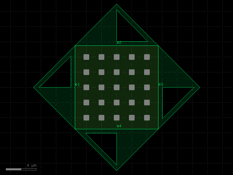
- gdsfactory.components.vias.via_stack_m1_mtop(size=(11.0, 11.0), *, layers=('M1', 'M2', 'MTOP'), layer_offsets=None, vias=('via1', 'via2', None), layer_to_port_orientations=None, correct_size=False, slot_horizontal=False, slot_vertical=False, port_orientations=(180, 90, 0, -90))#
Rectangular via array stack.
You can use it to connect different metal layers or metals to silicon. You can use the naming convention via_stack_layerSource_layerDestination contains 4 ports (e1, e2, e3, e4)
also know as Via array http://www.vlsi-expert.com/2017/12/vias.html
- Parameters:
size (Size) – of the layers.
layers (LayerSpecs) – layers on which to draw rectangles.
layer_offsets (Floats | tuple[float | tuple[float, float], ...] | None) – Optional offsets for each layer with respect to size. positive grows, negative shrinks the size. If a tuple, it is the offset in x and y.
vias (Sequence[ComponentSpec | None]) – vias to use to fill the rectangles.
layer_to_port_orientations (dict[LayerSpec, list[int]] | None) – dictionary of layer to port_orientations.
correct_size (bool) – if True, if the specified dimensions are too small it increases them to the minimum possible to fit a via.
slot_horizontal (bool) – if True, then vias are horizontal.
slot_vertical (bool) – if True, then vias are vertical.
port_orientations (Ints | None) – list of port_orientations to add. None does not add ports.
- Return type:
import gdsfactory as gf
gf.gpdk.PDK.activate()
c = gf.components.via_stack_m1_mtop(size=(11, 11), layers=('M1', 'M2', 'MTOP'), correct_size=False, slot_horizontal=False, slot_vertical=False, port_orientations=(180, 90, 0, -90)).copy()
c.draw_ports()
c.plot()
(Source code, png, hires.png, pdf)
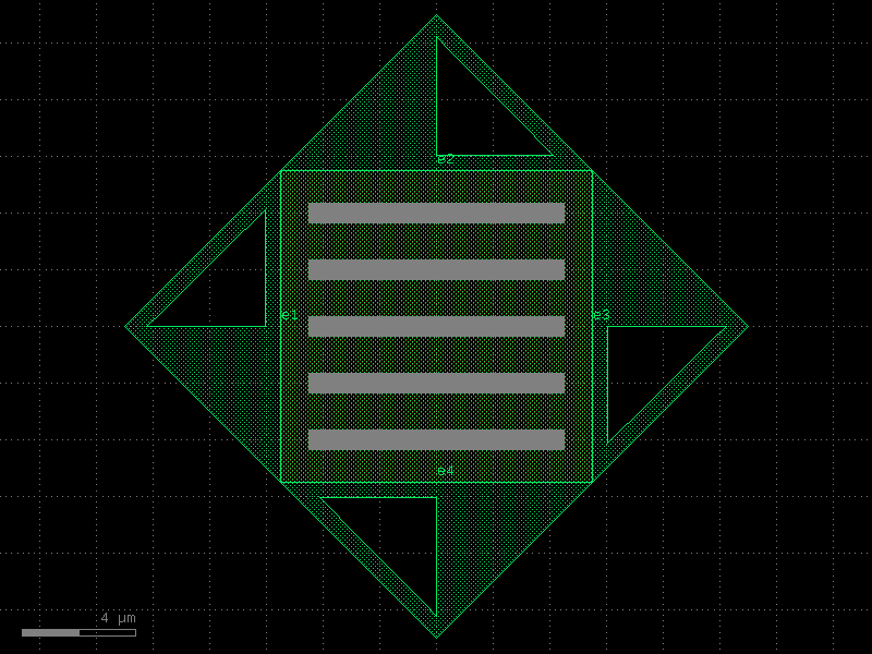
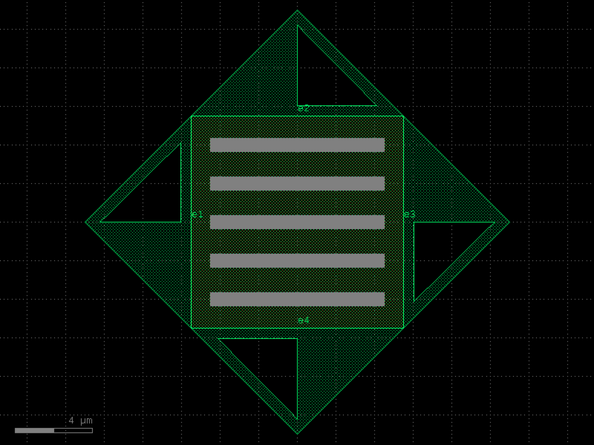

- gdsfactory.components.vias.via_stack_m2_m3(size=(11.0, 11.0), *, layers=('M2', 'MTOP'), layer_offsets=None, vias=('via2', None), layer_to_port_orientations=None, correct_size=False, slot_horizontal=False, slot_vertical=False, port_orientations=(180, 90, 0, -90))#
Rectangular via array stack.
You can use it to connect different metal layers or metals to silicon. You can use the naming convention via_stack_layerSource_layerDestination contains 4 ports (e1, e2, e3, e4)
also know as Via array http://www.vlsi-expert.com/2017/12/vias.html
- Parameters:
size (Size) – of the layers.
layers (LayerSpecs) – layers on which to draw rectangles.
layer_offsets (Floats | tuple[float | tuple[float, float], ...] | None) – Optional offsets for each layer with respect to size. positive grows, negative shrinks the size. If a tuple, it is the offset in x and y.
vias (Sequence[ComponentSpec | None]) – vias to use to fill the rectangles.
layer_to_port_orientations (dict[LayerSpec, list[int]] | None) – dictionary of layer to port_orientations.
correct_size (bool) – if True, if the specified dimensions are too small it increases them to the minimum possible to fit a via.
slot_horizontal (bool) – if True, then vias are horizontal.
slot_vertical (bool) – if True, then vias are vertical.
port_orientations (Ints | None) – list of port_orientations to add. None does not add ports.
- Return type:
import gdsfactory as gf
gf.gpdk.PDK.activate()
c = gf.components.via_stack_m2_m3(size=(11, 11), layers=('M2', 'MTOP'), correct_size=False, slot_horizontal=False, slot_vertical=False, port_orientations=(180, 90, 0, -90)).copy()
c.draw_ports()
c.plot()
(Source code, png, hires.png, pdf)
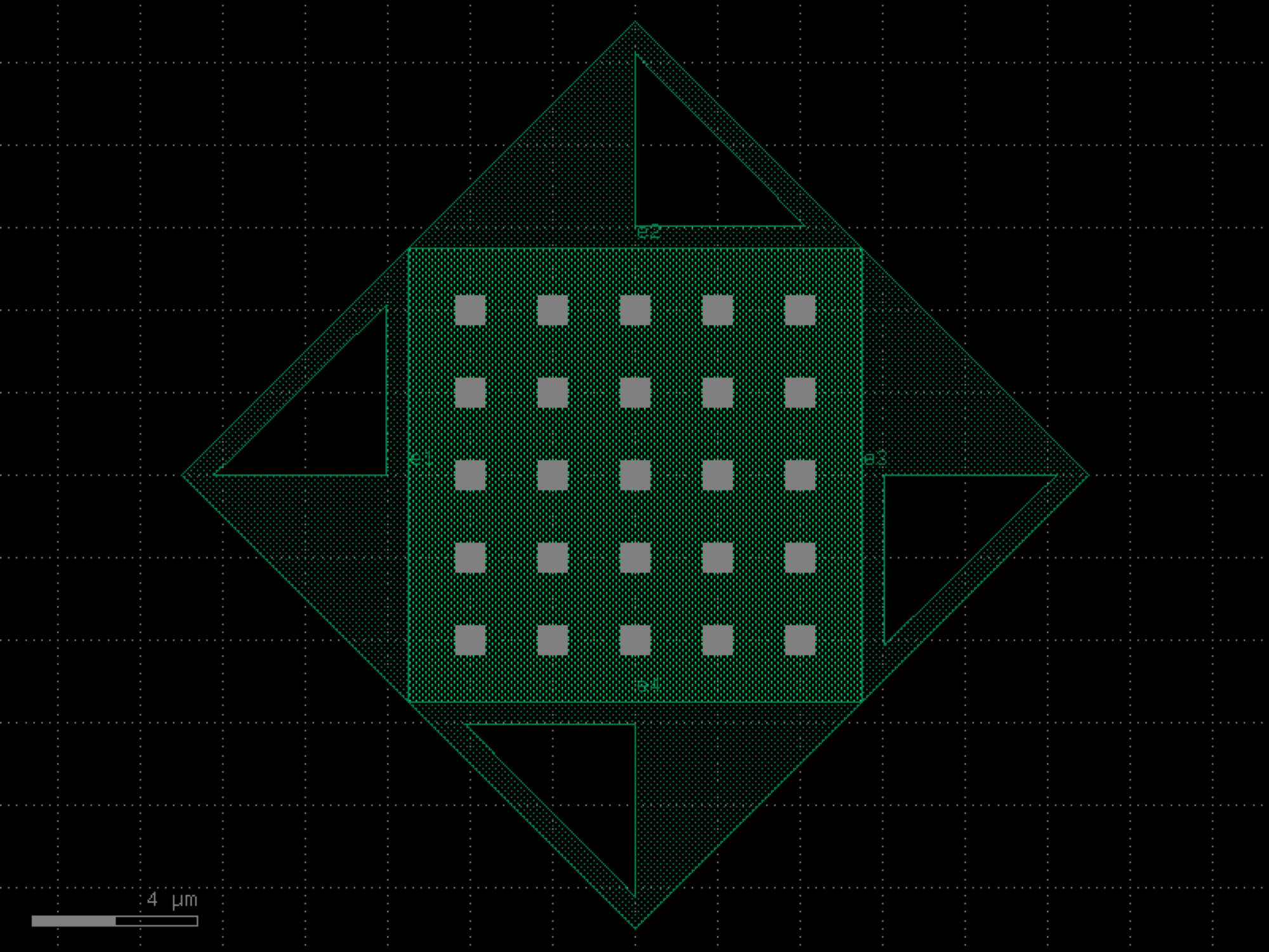
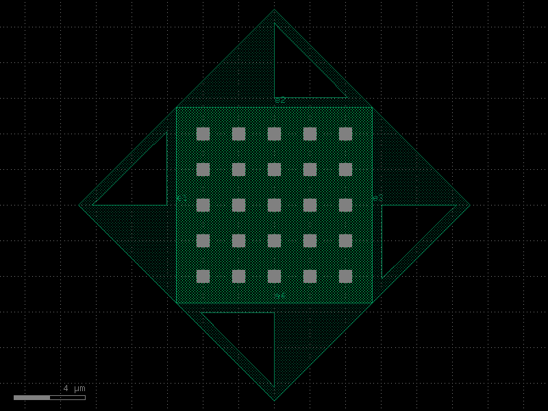
- gdsfactory.components.vias.via_stack_npp_m1(size=(11.0, 11.0), *, layers=('WG', 'NPP', 'M1'), layer_offsets=None, vias=(None, None, 'viac'), layer_to_port_orientations=None, correct_size=False, slot_horizontal=False, slot_vertical=False, port_orientations=(180, 90, 0, -90))#
Rectangular via array stack.
You can use it to connect different metal layers or metals to silicon. You can use the naming convention via_stack_layerSource_layerDestination contains 4 ports (e1, e2, e3, e4)
also know as Via array http://www.vlsi-expert.com/2017/12/vias.html
- Parameters:
size (Size) – of the layers.
layers (LayerSpecs) – layers on which to draw rectangles.
layer_offsets (Floats | tuple[float | tuple[float, float], ...] | None) – Optional offsets for each layer with respect to size. positive grows, negative shrinks the size. If a tuple, it is the offset in x and y.
vias (Sequence[ComponentSpec | None]) – vias to use to fill the rectangles.
layer_to_port_orientations (dict[LayerSpec, list[int]] | None) – dictionary of layer to port_orientations.
correct_size (bool) – if True, if the specified dimensions are too small it increases them to the minimum possible to fit a via.
slot_horizontal (bool) – if True, then vias are horizontal.
slot_vertical (bool) – if True, then vias are vertical.
port_orientations (Ints | None) – list of port_orientations to add. None does not add ports.
- Return type:
import gdsfactory as gf
gf.gpdk.PDK.activate()
c = gf.components.via_stack_npp_m1(size=(11, 11), layers=('WG', 'NPP', 'M1'), correct_size=False, slot_horizontal=False, slot_vertical=False, port_orientations=(180, 90, 0, -90)).copy()
c.draw_ports()
c.plot()
(Source code, png, hires.png, pdf)
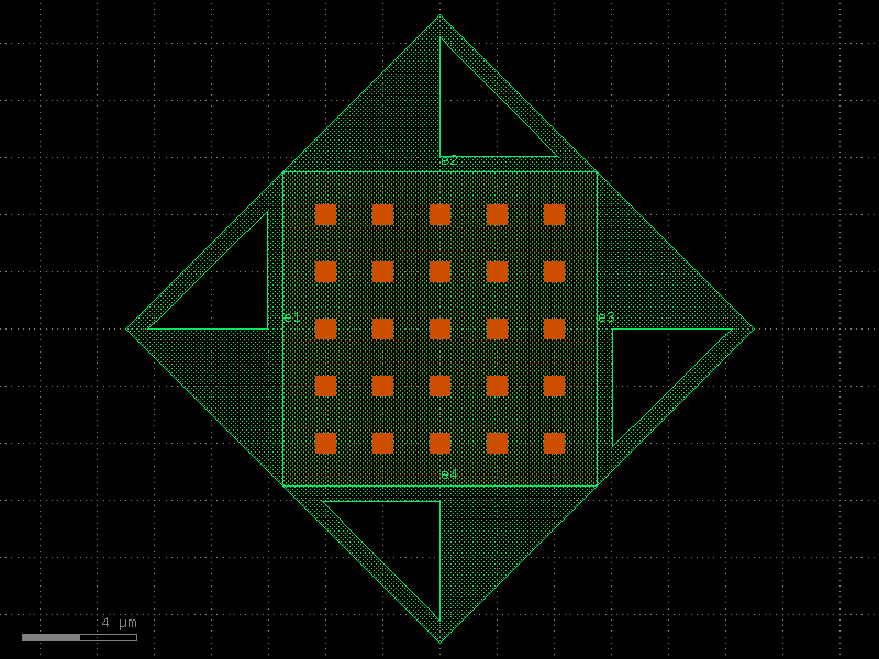
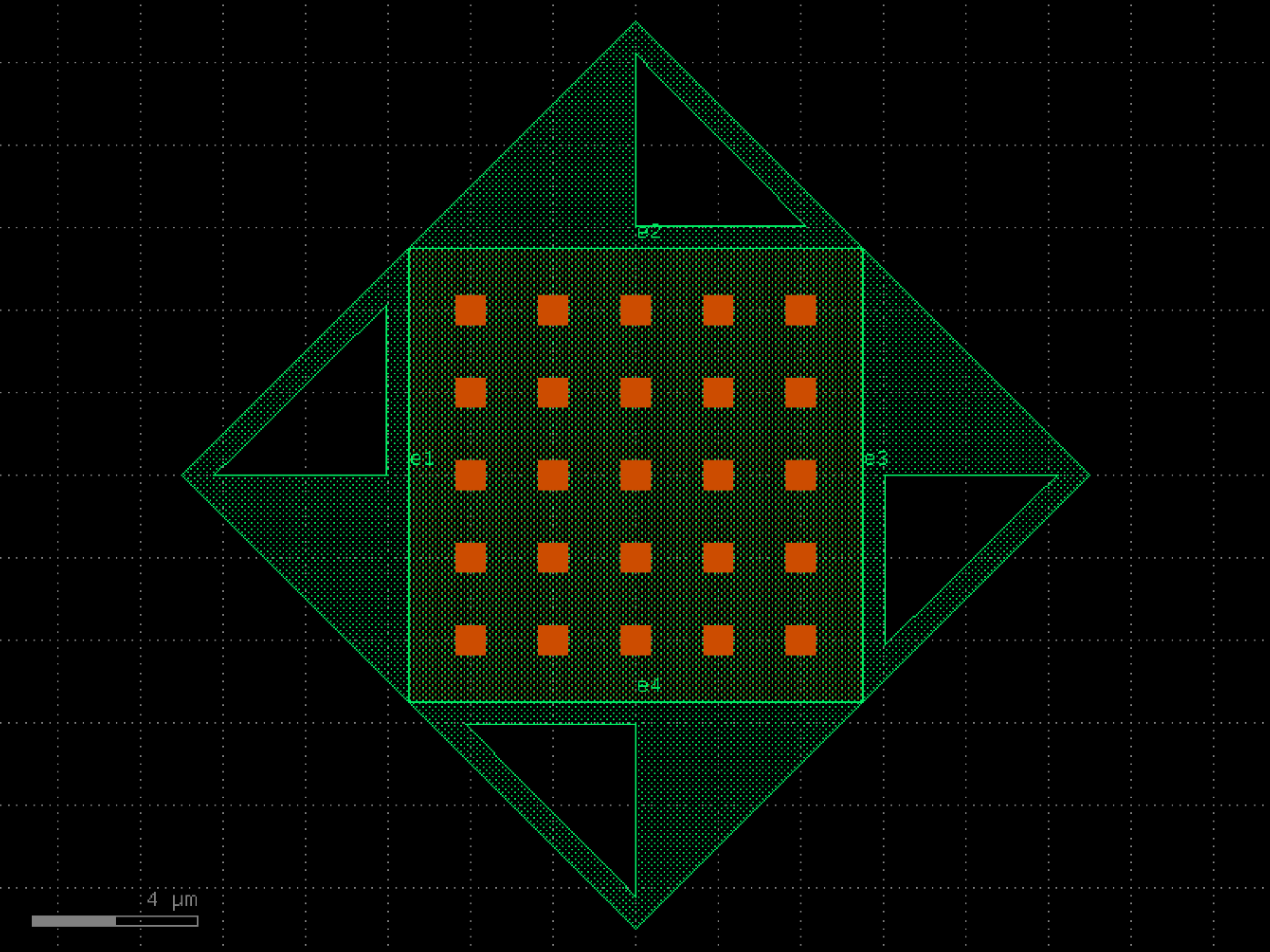

- gdsfactory.components.vias.via_stack_slab_m1(size=(11.0, 11.0), *, layers=('SLAB90', 'M1'), layer_offsets=None, vias=('viac', 'via1'), layer_to_port_orientations=None, correct_size=False, slot_horizontal=False, slot_vertical=False, port_orientations=(180, 90, 0, -90))#
Rectangular via array stack.
You can use it to connect different metal layers or metals to silicon. You can use the naming convention via_stack_layerSource_layerDestination contains 4 ports (e1, e2, e3, e4)
also know as Via array http://www.vlsi-expert.com/2017/12/vias.html
- Parameters:
size (Size) – of the layers.
layers (LayerSpecs) – layers on which to draw rectangles.
layer_offsets (Floats | tuple[float | tuple[float, float], ...] | None) – Optional offsets for each layer with respect to size. positive grows, negative shrinks the size. If a tuple, it is the offset in x and y.
vias (Sequence[ComponentSpec | None]) – vias to use to fill the rectangles.
layer_to_port_orientations (dict[LayerSpec, list[int]] | None) – dictionary of layer to port_orientations.
correct_size (bool) – if True, if the specified dimensions are too small it increases them to the minimum possible to fit a via.
slot_horizontal (bool) – if True, then vias are horizontal.
slot_vertical (bool) – if True, then vias are vertical.
port_orientations (Ints | None) – list of port_orientations to add. None does not add ports.
- Return type:
import gdsfactory as gf
gf.gpdk.PDK.activate()
c = gf.components.via_stack_slab_m1(size=(11, 11), layers=('SLAB90', 'M1'), correct_size=False, slot_horizontal=False, slot_vertical=False, port_orientations=(180, 90, 0, -90)).copy()
c.draw_ports()
c.plot()
(Source code, png, hires.png, pdf)

- gdsfactory.components.vias.via_stack_slab_m1_horizontal(size=(11.0, 11.0), *, layers=('SLAB90', 'M1'), layer_offsets=None, vias=('viac', 'via1'), layer_to_port_orientations=None, correct_size=False, slot_horizontal=True, slot_vertical=False, port_orientations=(180, 90, 0, -90))#
Rectangular via array stack.
You can use it to connect different metal layers or metals to silicon. You can use the naming convention via_stack_layerSource_layerDestination contains 4 ports (e1, e2, e3, e4)
also know as Via array http://www.vlsi-expert.com/2017/12/vias.html
- Parameters:
size (Size) – of the layers.
layers (LayerSpecs) – layers on which to draw rectangles.
layer_offsets (Floats | tuple[float | tuple[float, float], ...] | None) – Optional offsets for each layer with respect to size. positive grows, negative shrinks the size. If a tuple, it is the offset in x and y.
vias (Sequence[ComponentSpec | None]) – vias to use to fill the rectangles.
layer_to_port_orientations (dict[LayerSpec, list[int]] | None) – dictionary of layer to port_orientations.
correct_size (bool) – if True, if the specified dimensions are too small it increases them to the minimum possible to fit a via.
slot_horizontal (bool) – if True, then vias are horizontal.
slot_vertical (bool) – if True, then vias are vertical.
port_orientations (Ints | None) – list of port_orientations to add. None does not add ports.
- Return type:
import gdsfactory as gf
gf.gpdk.PDK.activate()
c = gf.components.via_stack_slab_m1_horizontal(size=(11, 11), layers=('SLAB90', 'M1'), correct_size=False, slot_horizontal=True, slot_vertical=False, port_orientations=(180, 90, 0, -90)).copy()
c.draw_ports()
c.plot()
(Source code, png, hires.png, pdf)
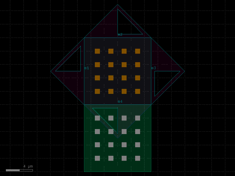
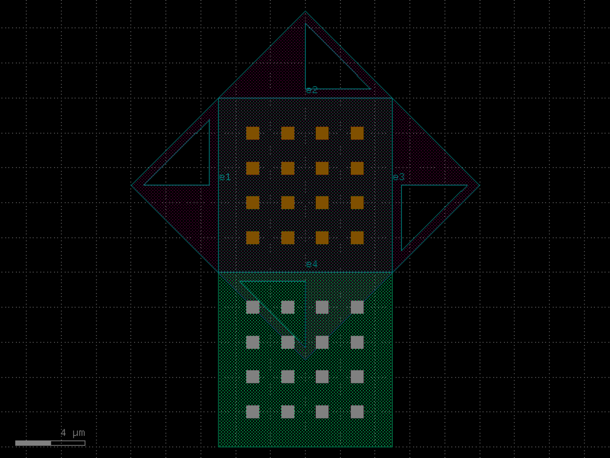

- gdsfactory.components.vias.via_stack_slab_m2(size=(11.0, 11.0), *, layers=('SLAB90', 'M1', 'M2'), layer_offsets=None, vias=('viac', 'via1', None), layer_to_port_orientations=None, correct_size=False, slot_horizontal=False, slot_vertical=False, port_orientations=(180, 90, 0, -90))#
Rectangular via array stack.
You can use it to connect different metal layers or metals to silicon. You can use the naming convention via_stack_layerSource_layerDestination contains 4 ports (e1, e2, e3, e4)
also know as Via array http://www.vlsi-expert.com/2017/12/vias.html
- Parameters:
size (Size) – of the layers.
layers (LayerSpecs) – layers on which to draw rectangles.
layer_offsets (Floats | tuple[float | tuple[float, float], ...] | None) – Optional offsets for each layer with respect to size. positive grows, negative shrinks the size. If a tuple, it is the offset in x and y.
vias (Sequence[ComponentSpec | None]) – vias to use to fill the rectangles.
layer_to_port_orientations (dict[LayerSpec, list[int]] | None) – dictionary of layer to port_orientations.
correct_size (bool) – if True, if the specified dimensions are too small it increases them to the minimum possible to fit a via.
slot_horizontal (bool) – if True, then vias are horizontal.
slot_vertical (bool) – if True, then vias are vertical.
port_orientations (Ints | None) – list of port_orientations to add. None does not add ports.
- Return type:
import gdsfactory as gf
gf.gpdk.PDK.activate()
c = gf.components.via_stack_slab_m2(size=(11, 11), layers=('SLAB90', 'M1', 'M2'), correct_size=False, slot_horizontal=False, slot_vertical=False, port_orientations=(180, 90, 0, -90)).copy()
c.draw_ports()
c.plot()
(Source code, png, hires.png, pdf)
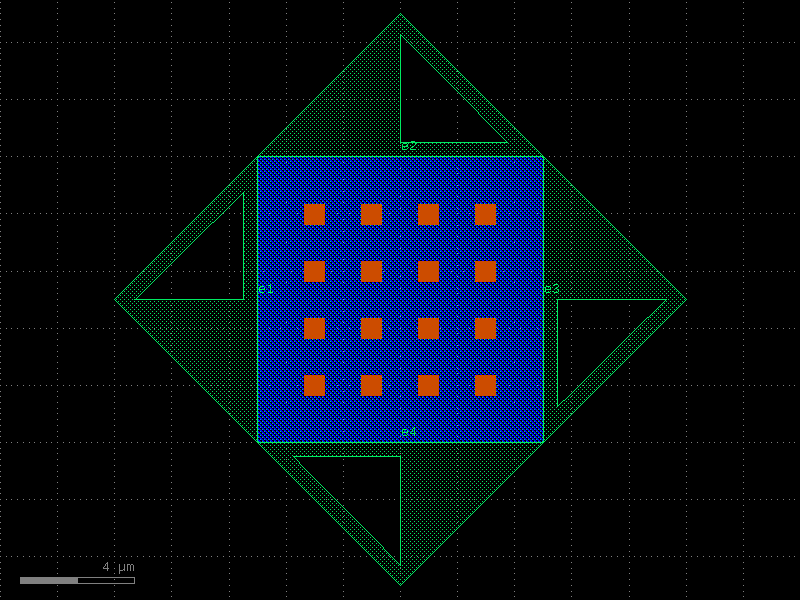
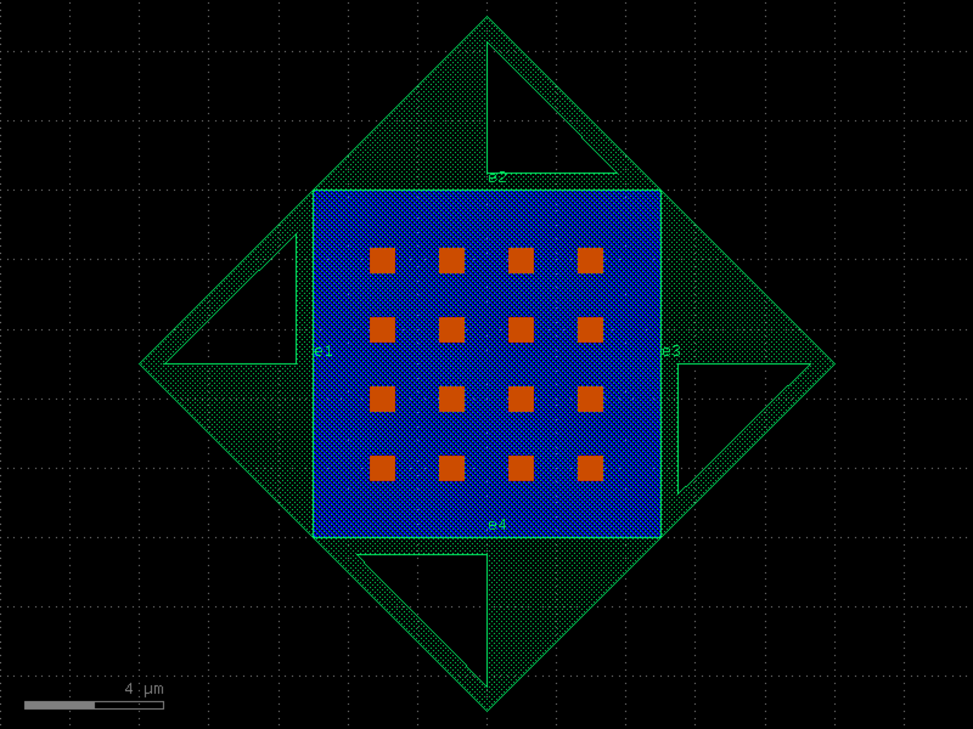

- gdsfactory.components.vias.via_stack_slab_npp_m3(size=(11.0, 11.0), *, layers=('SLAB90', 'NPP', 'M1'), layer_offsets=None, vias=(None, None, 'viac'), layer_to_port_orientations=None, correct_size=False, slot_horizontal=False, slot_vertical=False, port_orientations=(180, 90, 0, -90))#
Rectangular via array stack.
You can use it to connect different metal layers or metals to silicon. You can use the naming convention via_stack_layerSource_layerDestination contains 4 ports (e1, e2, e3, e4)
also know as Via array http://www.vlsi-expert.com/2017/12/vias.html
- Parameters:
size (Size) – of the layers.
layers (LayerSpecs) – layers on which to draw rectangles.
layer_offsets (Floats | tuple[float | tuple[float, float], ...] | None) – Optional offsets for each layer with respect to size. positive grows, negative shrinks the size. If a tuple, it is the offset in x and y.
vias (Sequence[ComponentSpec | None]) – vias to use to fill the rectangles.
layer_to_port_orientations (dict[LayerSpec, list[int]] | None) – dictionary of layer to port_orientations.
correct_size (bool) – if True, if the specified dimensions are too small it increases them to the minimum possible to fit a via.
slot_horizontal (bool) – if True, then vias are horizontal.
slot_vertical (bool) – if True, then vias are vertical.
port_orientations (Ints | None) – list of port_orientations to add. None does not add ports.
- Return type:
import gdsfactory as gf
gf.gpdk.PDK.activate()
c = gf.components.via_stack_slab_npp_m3(size=(11, 11), layers=('SLAB90', 'NPP', 'M1'), correct_size=False, slot_horizontal=False, slot_vertical=False, port_orientations=(180, 90, 0, -90)).copy()
c.draw_ports()
c.plot()
(Source code, png, hires.png, pdf)
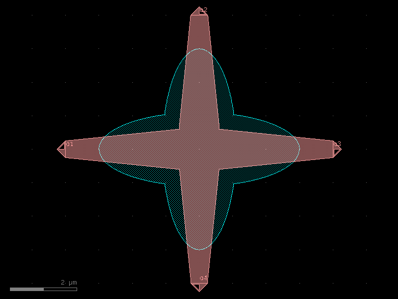
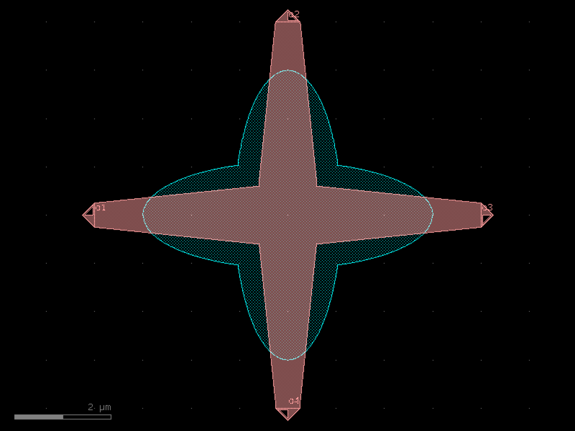

- gdsfactory.components.vias.via_stack_with_offset(layers=('PPP', 'M1'), size=(10, 10), sizes=None, layer_offsets=None, vias=(None, 'viac'), offsets=None, layer_to_port_orientations=None)[source]#
Rectangular layer transition with offset between layers.
- Parameters:
layers (LayerSpecs) – layer specs between vias.
size (Size | None) – for all vias array.
sizes (Sequence[Size] | None) – Optional size for each via array. Overrides size.
layer_offsets (Sequence[float] | None) – Optional offsets for each layer with respect to size. positive grows, negative shrinks the size.
vias (Sequence[ComponentSpec | None]) – via spec for previous layer. None for no via.
offsets (Sequence[float] | None) – optional offset for each layer relatively to the previous one. By default it only offsets by size[1] if there is a via.
layer_to_port_orientations (dict[LayerSpec, list[int]] | None) – Optional dictionary with layer to port orientations.
- Return type:
side view __________________________ | | | | layers[2] |__________________________| vias[2] = None | | | layer_offsets[1]+size | layers[1] |__________________________| | | vias[1] ___|_____|__ | | | sizes[0] | layers[0] |____________| vias[0] = None
import gdsfactory as gf
gf.gpdk.PDK.activate()
c = gf.components.via_stack_with_offset(layers=('PPP', 'M1'), size=(10, 10)).copy()
c.draw_ports()
c.plot()
(Source code, png, hires.png, pdf)
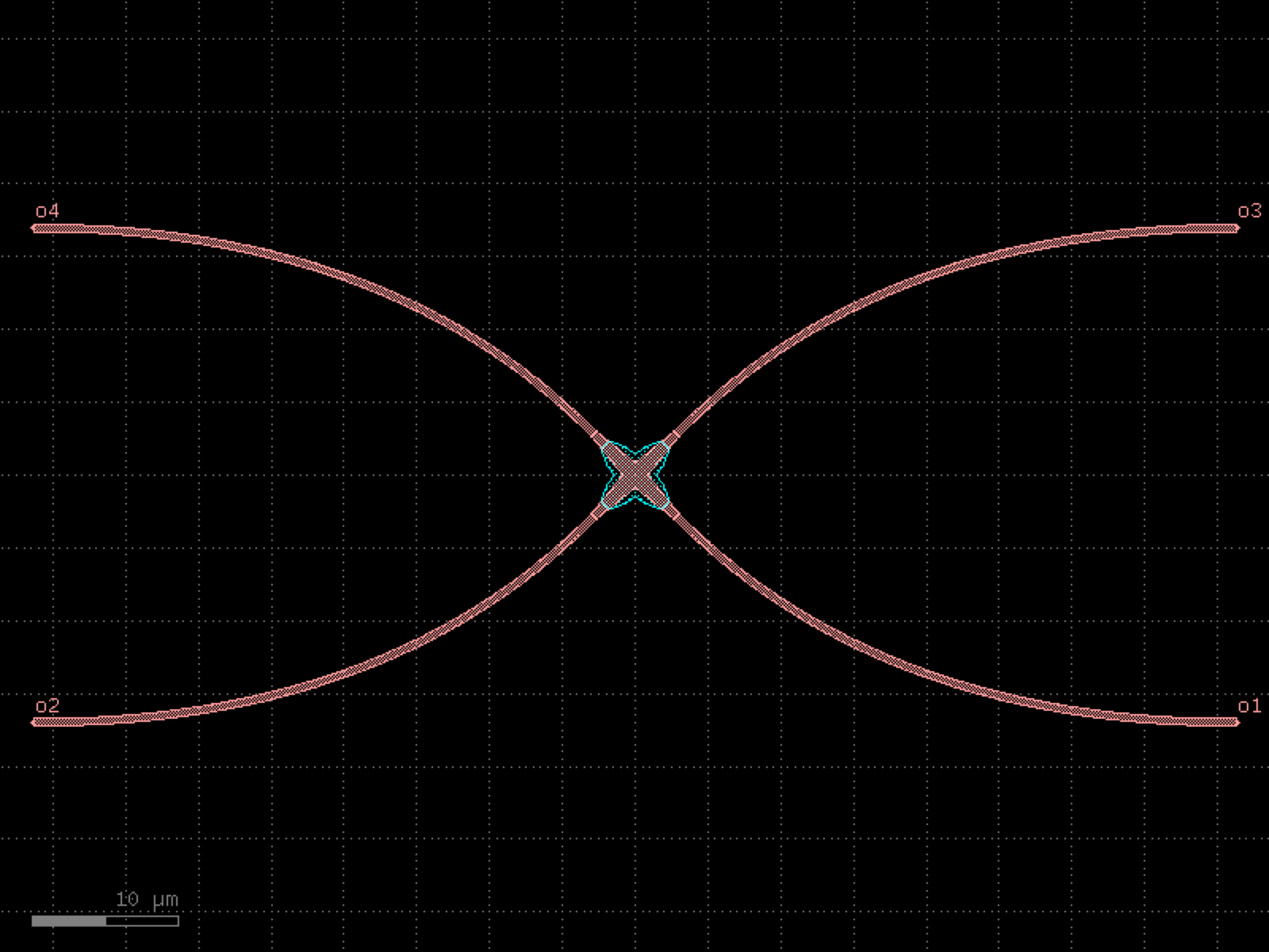
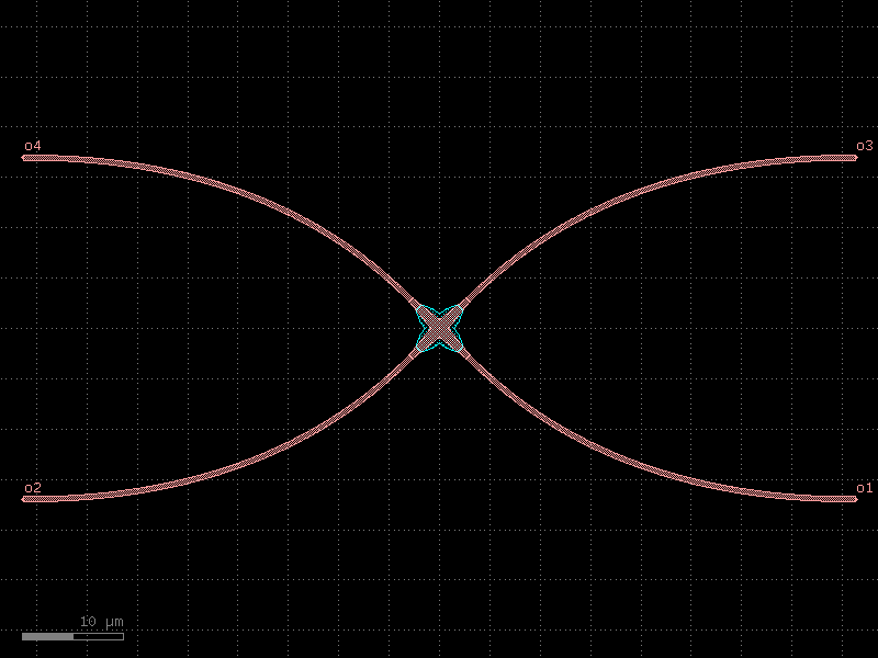
- gdsfactory.components.vias.via_stack_with_offset_m1_m3(*, layers=('M1', 'M2', 'MTOP'), size=(10, 10), sizes=None, layer_offsets=None, vias=(None, 'via1', 'via2'), offsets=None, layer_to_port_orientations=None)#
Rectangular layer transition with offset between layers.
- Parameters:
layers (LayerSpecs) – layer specs between vias.
size (Size | None) – for all vias array.
sizes (Sequence[Size] | None) – Optional size for each via array. Overrides size.
layer_offsets (Sequence[float] | None) – Optional offsets for each layer with respect to size. positive grows, negative shrinks the size.
vias (Sequence[ComponentSpec | None]) – via spec for previous layer. None for no via.
offsets (Sequence[float] | None) – optional offset for each layer relatively to the previous one. By default it only offsets by size[1] if there is a via.
layer_to_port_orientations (dict[LayerSpec, list[int]] | None) – Optional dictionary with layer to port orientations.
- Return type:
side view __________________________ | | | | layers[2] |__________________________| vias[2] = None | | | layer_offsets[1]+size | layers[1] |__________________________| | | vias[1] ___|_____|__ | | | sizes[0] | layers[0] |____________| vias[0] = None
import gdsfactory as gf
gf.gpdk.PDK.activate()
c = gf.components.via_stack_with_offset_m1_m3(layers=('M1', 'M2', 'MTOP'), size=(10, 10)).copy()
c.draw_ports()
c.plot()
(Source code, png, hires.png, pdf)
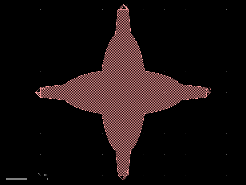
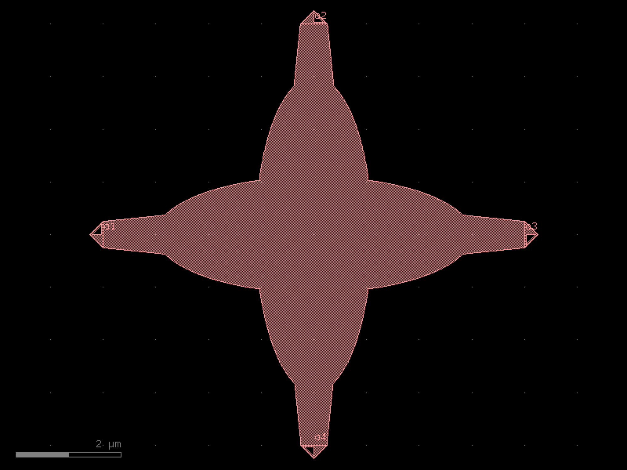

- gdsfactory.components.vias.via_stack_with_offset_ppp_m1(*, layers=('PPP', 'M1'), size=(10, 10), sizes=None, layer_offsets=None, vias=(None, 'viac'), offsets=None, layer_to_port_orientations=None)#
Rectangular layer transition with offset between layers.
- Parameters:
layers (LayerSpecs) – layer specs between vias.
size (Size | None) – for all vias array.
sizes (Sequence[Size] | None) – Optional size for each via array. Overrides size.
layer_offsets (Sequence[float] | None) – Optional offsets for each layer with respect to size. positive grows, negative shrinks the size.
vias (Sequence[ComponentSpec | None]) – via spec for previous layer. None for no via.
offsets (Sequence[float] | None) – optional offset for each layer relatively to the previous one. By default it only offsets by size[1] if there is a via.
layer_to_port_orientations (dict[LayerSpec, list[int]] | None) – Optional dictionary with layer to port orientations.
- Return type:
side view __________________________ | | | | layers[2] |__________________________| vias[2] = None | | | layer_offsets[1]+size | layers[1] |__________________________| | | vias[1] ___|_____|__ | | | sizes[0] | layers[0] |____________| vias[0] = None
import gdsfactory as gf
gf.gpdk.PDK.activate()
c = gf.components.via_stack_with_offset_ppp_m1(layers=('PPP', 'M1'), size=(10, 10)).copy()
c.draw_ports()
c.plot()
(Source code, png, hires.png, pdf)
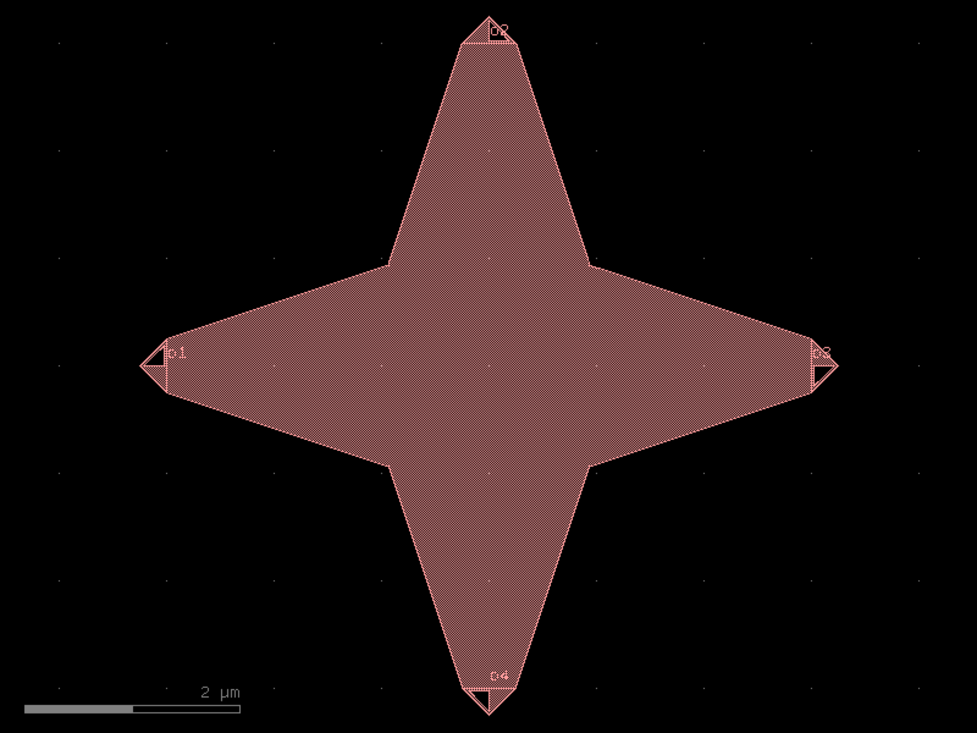
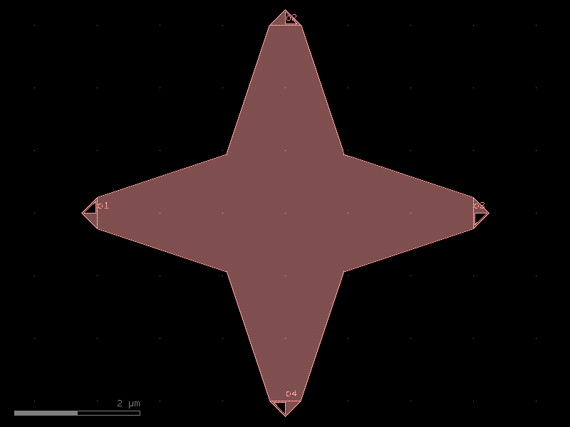
waveguides#
- gdsfactory.components.waveguides.crossing(arm=<function crossing_arm>)[source]#
Waveguide crossing.
- Parameters:
arm (ComponentSpec) – arm spec.
- Return type:
import gdsfactory as gf
gf.gpdk.PDK.activate()
c = gf.components.crossing().copy()
c.draw_ports()
c.plot()
(Source code, png, hires.png, pdf)
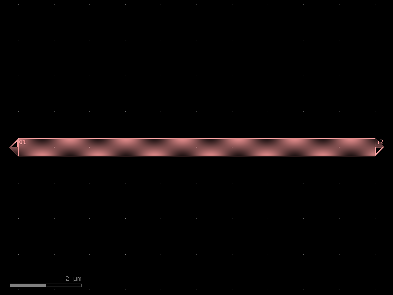
- gdsfactory.components.waveguides.crossing45(crossing=<function crossing>, port_spacing=40.0, dx=None, alpha=0.08, npoints=101, cross_section='strip', cross_section_bends='strip')[source]#
Returns 45deg crossing with bends.
- Parameters:
crossing (ComponentSpec) – crossing function.
port_spacing (float) – target I/O port spacing.
dx (float | None) – target length.
alpha (float) – optimization parameter. diminish it for tight bends, increase it if raises assertion angle errors
npoints (int) – number of points.
cross_section (CrossSectionSpec) – cross_section spec.
cross_section_bends (CrossSectionSpec) – cross_section spec.
- Return type:
The 45 Degree crossing CANNOT be kept as an SRef since we only allow for multiples of 90Deg rotations in SRef.
---- ---- \ / X / \ --- ----
import gdsfactory as gf
gf.gpdk.PDK.activate()
c = gf.components.crossing45(port_spacing=40, alpha=0.08, npoints=101, cross_section='strip', cross_section_bends='strip').copy()
c.draw_ports()
c.plot()
(Source code, png, hires.png, pdf)
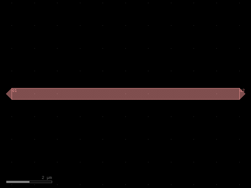
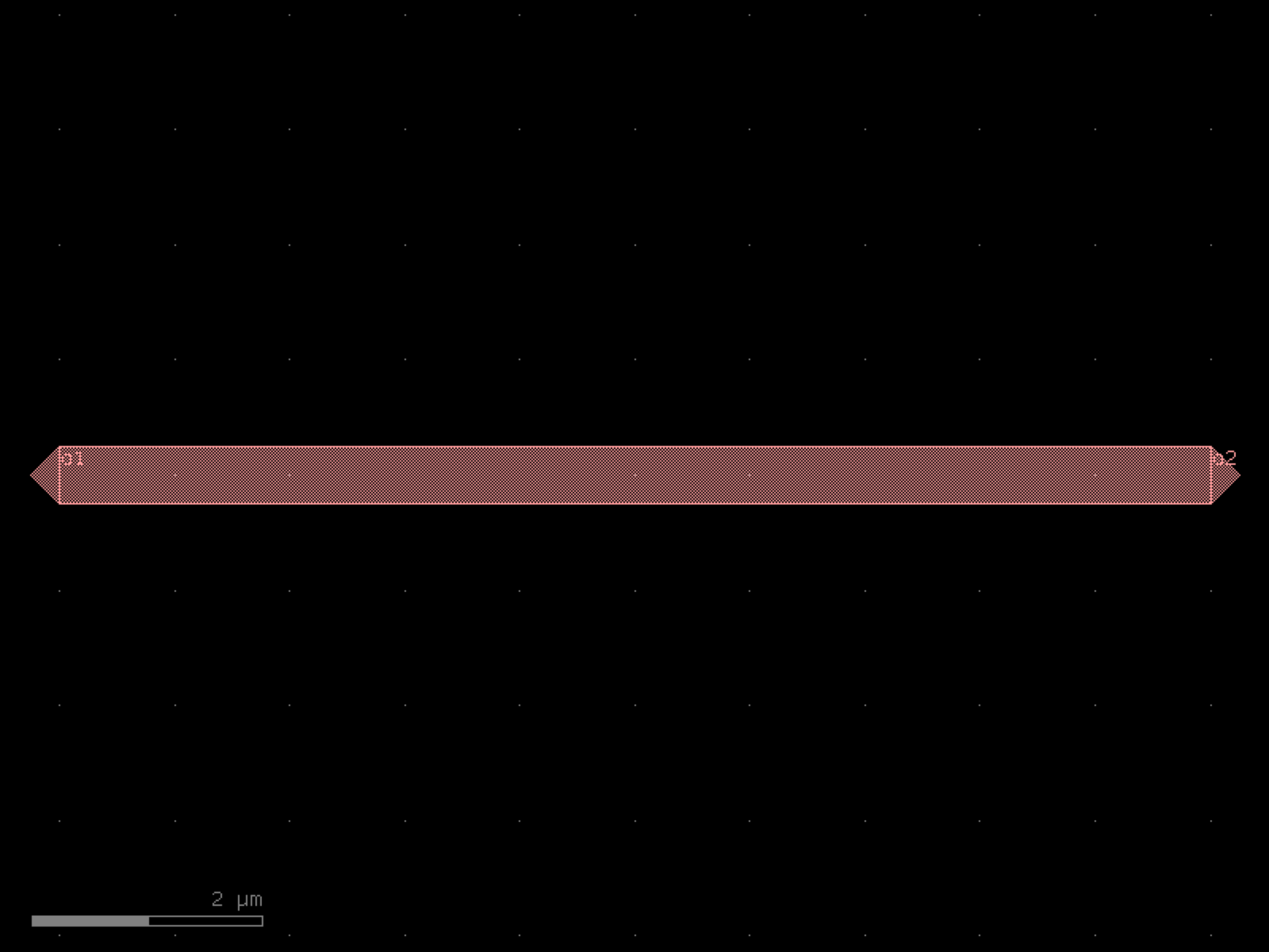

- gdsfactory.components.waveguides.crossing_etched(width=0.5, r1=3.0, r2=1.1, w=1.2, L=3.4, layer_wg='WG', layer_slab='SLAB150')[source]#
Waveguide crossing.
Full crossing has to be on WG layer (to start with a 220nm slab). Then we etch the ellipses down to 150nm slabs and we keep linear taper at 220nm.
- Parameters:
width (float) – input waveguides width.
r1 (float) – radii.
r2 (float) – radii.
w (float) – wide width.
L (float) – length.
layer_wg (LayerSpec) – waveguide layer.
layer_slab (LayerSpec) – shallow etch layer.
- Return type:
import gdsfactory as gf
gf.gpdk.PDK.activate()
c = gf.components.crossing_etched(width=0.5, r1=3, r2=1.1, w=1.2, L=3.4, layer_wg='WG', layer_slab='SLAB150').copy()
c.draw_ports()
c.plot()
(Source code, png, hires.png, pdf)
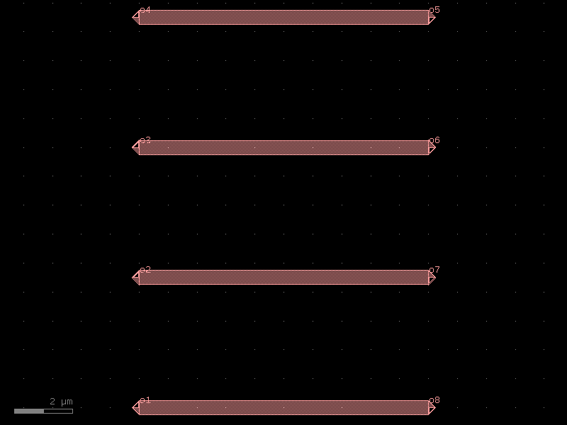
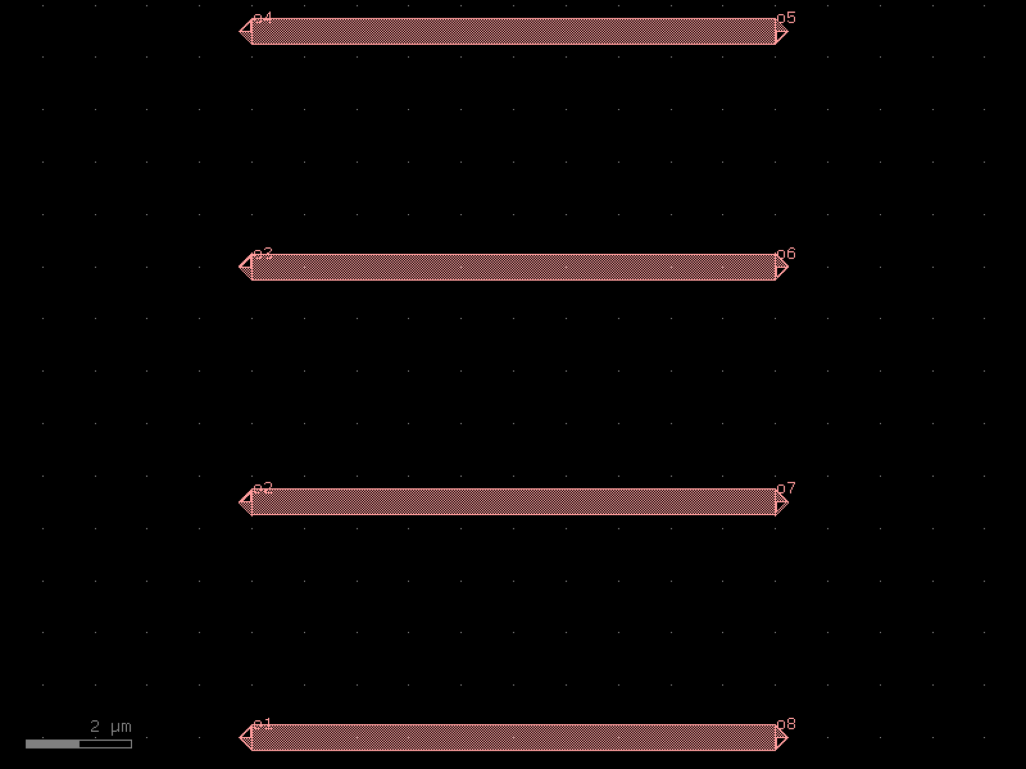

- gdsfactory.components.waveguides.crossing_linear_taper(width1=2.5, width2=0.5, length=3, cross_section='strip', taper='taper')[source]#
Returns Crossing based on a taper.
The default is a dummy taper.
- Parameters:
width1 (float) – input width.
width2 (float) – output width.
length (float) – taper length.
cross_section (CrossSectionSpec) – cross_section spec.
taper (ComponentSpec) – taper spec.
- Return type:
import gdsfactory as gf
gf.gpdk.PDK.activate()
c = gf.components.crossing_linear_taper(width1=2.5, width2=0.5, length=3, cross_section='strip', taper='taper').copy()
c.draw_ports()
c.plot()
(Source code, png, hires.png, pdf)
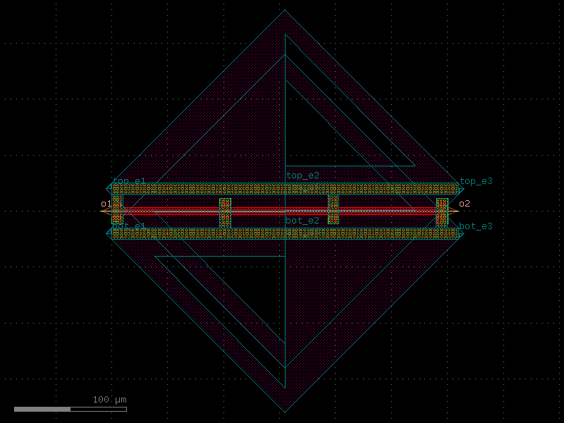
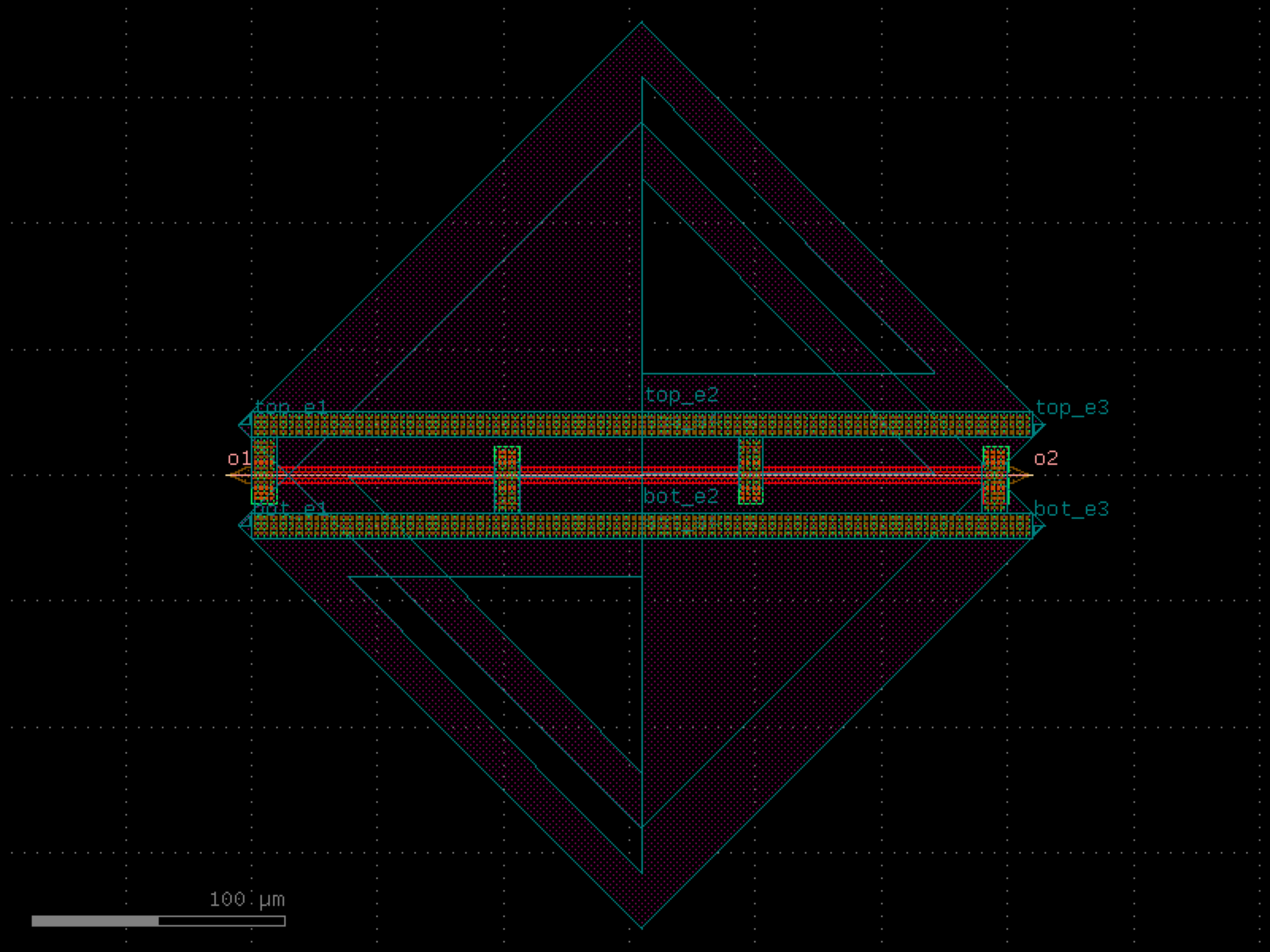

- gdsfactory.components.waveguides.straight(length=10.0, npoints=2, cross_section='strip', width=None)[source]#
Returns a Straight waveguide.
- Parameters:
length (float) – straight length (um).
npoints (int) – number of points.
cross_section (CrossSectionSpec) – specification (CrossSection, string or dict).
width (float | None) – width of the waveguide. If None, it will use the width of the cross_section.
- Return type:
o1 ──────────────── o2 length
import gdsfactory as gf
gf.gpdk.PDK.activate()
c = gf.components.straight(length=10, npoints=2, cross_section='strip').copy()
c.draw_ports()
c.plot()
(Source code, png, hires.png, pdf)
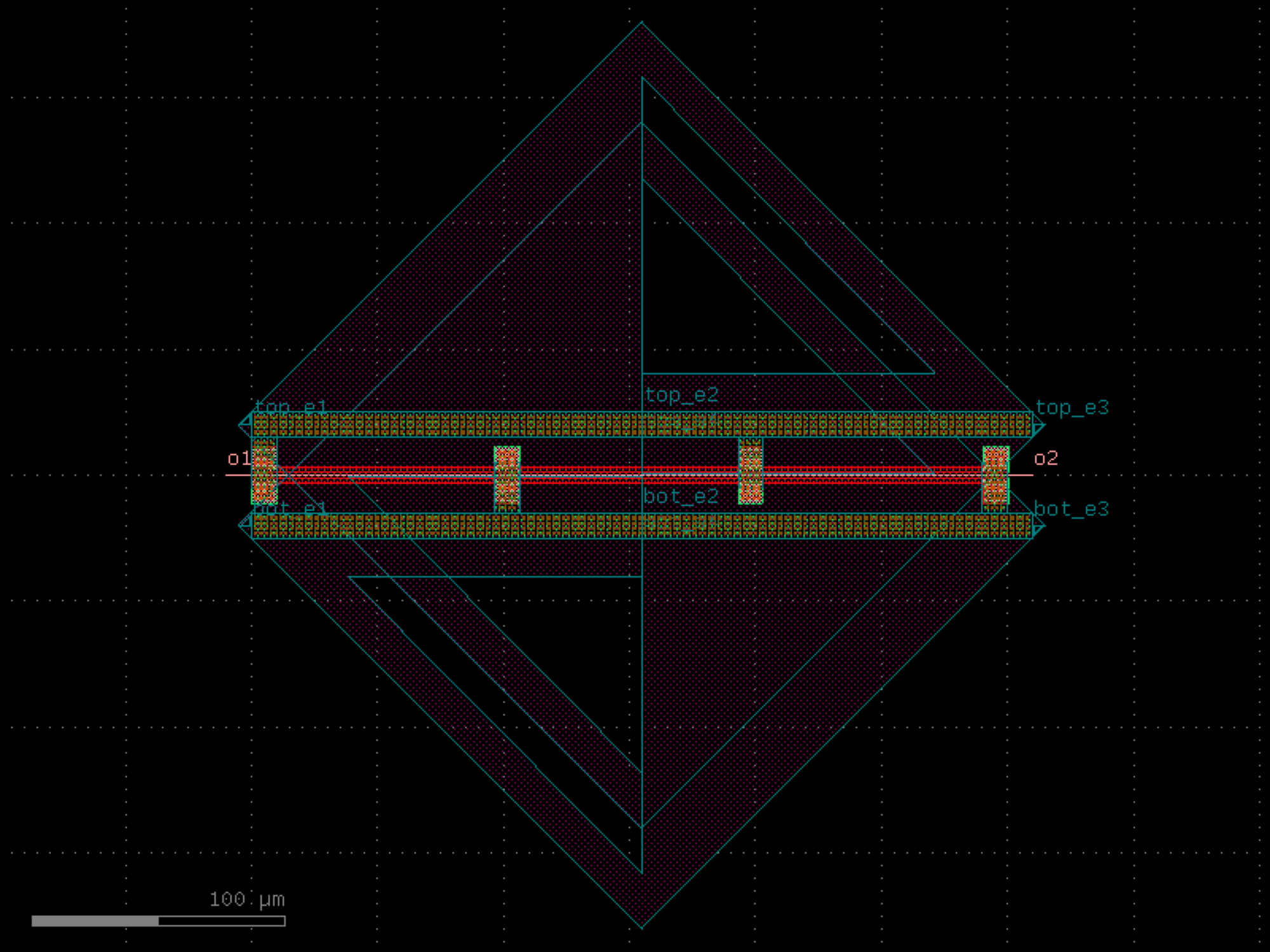
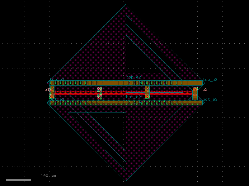
- gdsfactory.components.waveguides.straight_all_angle(length=10.0, npoints=2, cross_section='strip', width=None)[source]#
Returns a Straight waveguide with offgrid ports.
- Parameters:
length (float) – straight length (um).
npoints (int) – number of points.
cross_section (CrossSectionSpec) – specification (CrossSection, string or dict).
width (float | None) – width of the waveguide. If None, it will use the width of the cross_section.
- Return type:
o1 ──────────────── o2 length
import gdsfactory as gf
gf.gpdk.PDK.activate()
c = gf.components.straight_all_angle(length=10, npoints=2, cross_section='strip').copy()
c.draw_ports()
c.plot()
(Source code, png, hires.png, pdf)
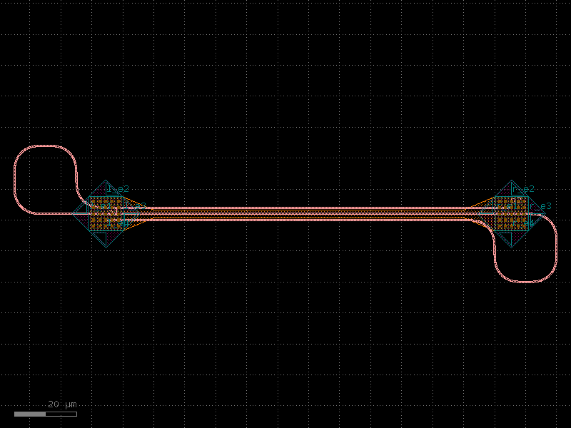
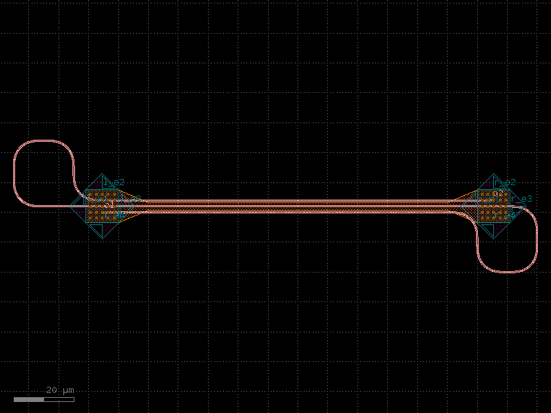
- gdsfactory.components.waveguides.straight_array(n=4, spacing=4.0, length=10.0, cross_section='strip')[source]#
Array of straights connected with grating couplers.
useful to align the 4 corners of the chip
- Parameters:
n (int) – number of straights.
spacing (float) – edge to edge straight spacing.
length (float) – straight length (um).
cross_section (CrossSectionSpec) – specification (CrossSection, string or dict).
- Return type:
import gdsfactory as gf
gf.gpdk.PDK.activate()
c = gf.components.straight_array(n=4, spacing=4, length=10, cross_section='strip').copy()
c.draw_ports()
c.plot()
(Source code, png, hires.png, pdf)
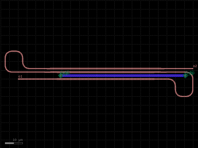
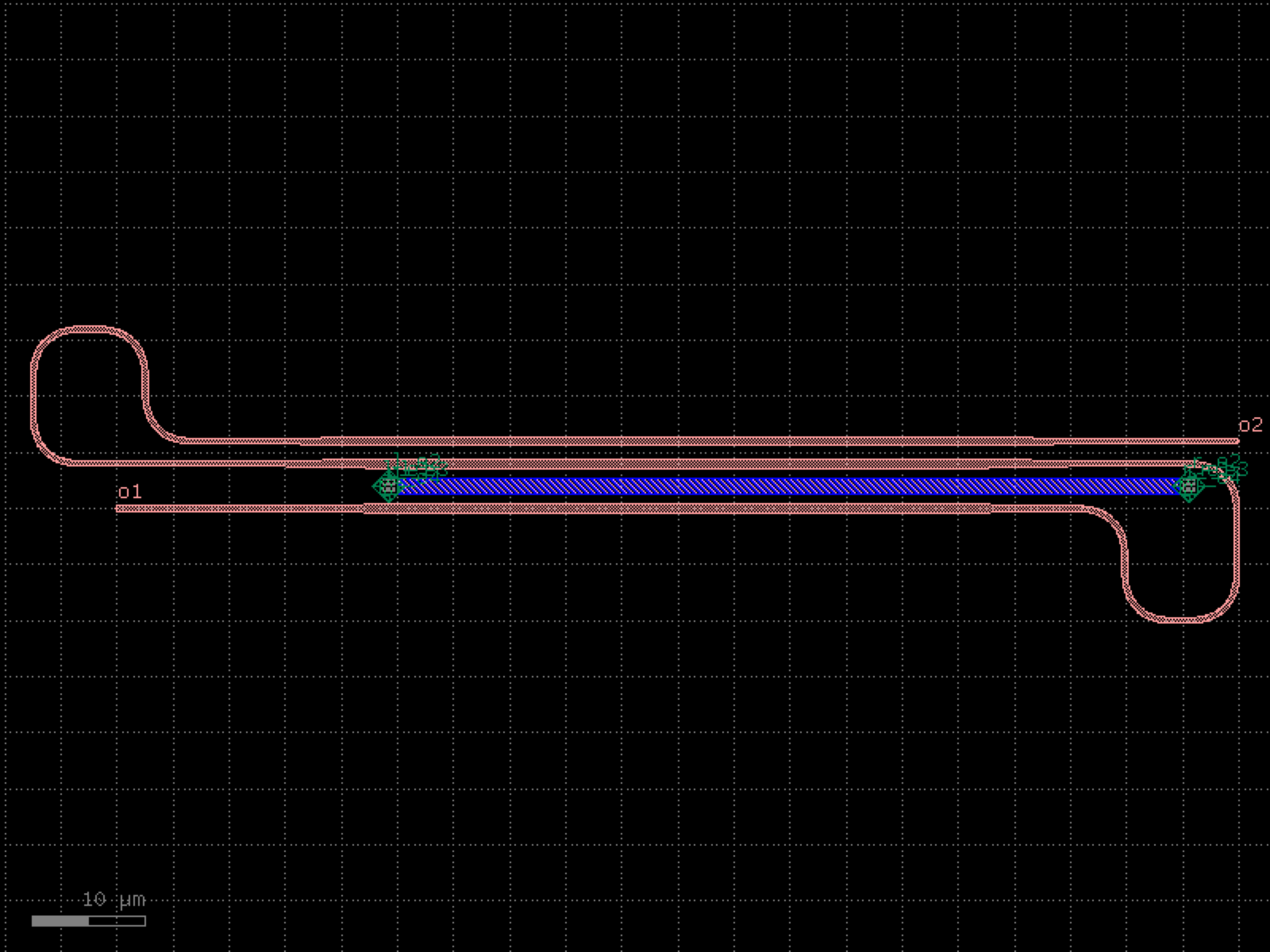

- gdsfactory.components.waveguides.straight_heater_doped_rib(length=320.0, nsections=3, cross_section='strip_rib_tip', cross_section_heater='rib_heater_doped', via_stack='via_stack_slab_npp_m3', via_stack_metal='via_stack_m1_mtop', via_stack_metal_size=(10.0, 10.0), via_stack_size=(10.0, 10.0), taper='taper_cross_section', heater_width=2.0, heater_gap=0.8, via_stack_gap=0.0, width=0.5, xoffset_tip1=0.2, xoffset_tip2=0.4)[source]#
Returns a doped thermal phase shifter.
dimensions from https://doi.org/10.1364/OE.27.010456
- Parameters:
length (float) – of the waveguide in um.
nsections (int) – between via_stacks.
cross_section (CrossSectionSpec) – for the input/output ports.
cross_section_heater (CrossSectionSpec) – for the heater.
via_stack (ComponentSpec | None) – optional function to connect the heater strip.
via_stack_metal (ComponentSpec | None) – function to connect the metal area.
via_stack_metal_size (Size) – x, y size in um.
via_stack_size (Size) – x, y size in um.
taper (ComponentSpec | None) – optional taper spec.
heater_width (float) – in um.
heater_gap (float) – in um.
via_stack_gap (float) – from edge of via_stack to waveguide.
width (float) – waveguide width on the ridge.
xoffset_tip1 (float) – distance in um from input taper to via_stack.
xoffset_tip2 (float) – distance in um from output taper to via_stack.
- Return type:
length |<--------------------------------------------->| | length_section | | <---------------------------> | | length_via_stack | | <-------> taper| | __________ _________ | | | | | | | | | via_stack|__________________| | | | | size | heater width | | | | /|__________|__________________|________|\ | | / | heater_gap | \ | |/ |______________________________________| \ | \ |_______________width__________________| / \ | | / \|_____________heater_gap______________ |/ | | | | | |____heater_width____| | | | | | |________| |________| taper cross_section_heater |<------width------>| ____________________ heater_gap slab_gap top_via_stack | |<---------->| bot_via_stack <--> ___ ______________________| |___________________________|___ | | | undoped Si | | | | |layer_heater| intrinsic region |layer_heater | | |___|____________|__________________________________________|______________|___| <------------> heater_width <------------------------------------------------------------------------------> slab_width
import gdsfactory as gf
gf.gpdk.PDK.activate()
c = gf.components.straight_heater_doped_rib(length=320, nsections=3, cross_section='strip_rib_tip', cross_section_heater='rib_heater_doped', via_stack='via_stack_slab_npp_m3', via_stack_metal='via_stack_m1_mtop', via_stack_metal_size=(10, 10), via_stack_size=(10, 10), taper='taper_cross_section', heater_width=2, heater_gap=0.8, via_stack_gap=0, width=0.5, xoffset_tip1=0.2, xoffset_tip2=0.4).copy()
c.draw_ports()
c.plot()
(Source code, png, hires.png, pdf)
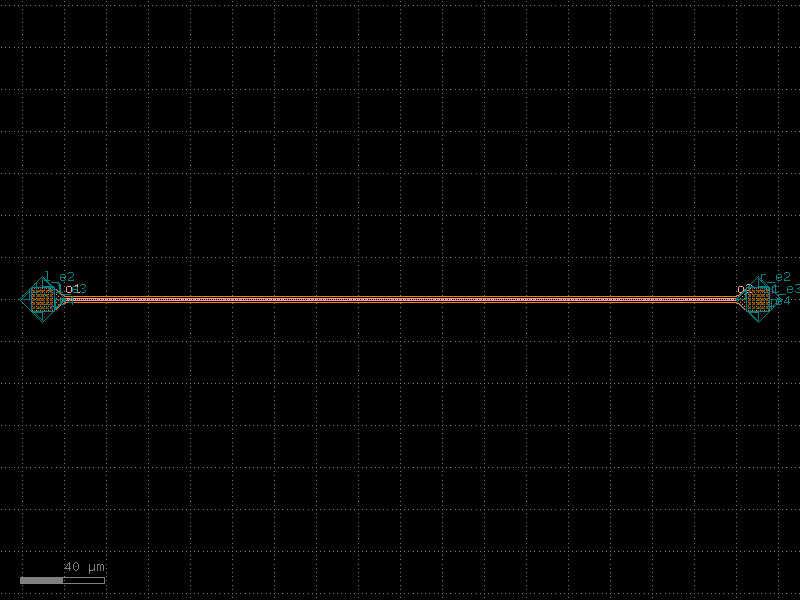
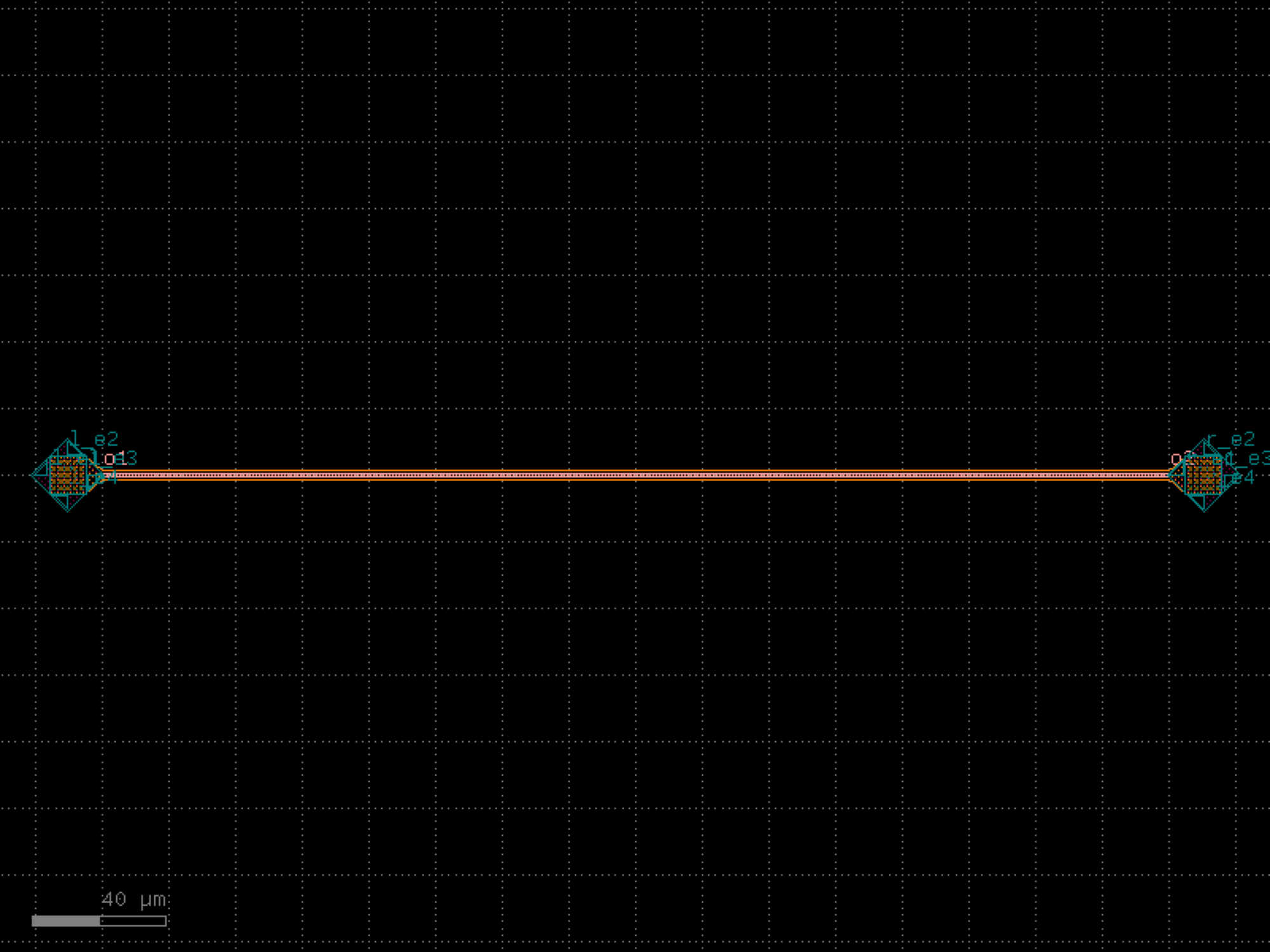

- gdsfactory.components.waveguides.straight_heater_doped_strip(length=320.0, nsections=3, cross_section='strip_heater_doped', cross_section_heater='rib_heater_doped', via_stack='via_stack_npp_m1', via_stack_metal='via_stack_m1_mtop', via_stack_metal_size=(10.0, 10.0), via_stack_size=(10.0, 10.0), taper='taper_cross_section', heater_width=2.0, heater_gap=0.8, via_stack_gap=0.0, width=0.5, xoffset_tip1=0.2, xoffset_tip2=0.4)[source]#
Top view.
- Parameters:
length (float) – of the waveguide in um.
nsections (int) – between via_stacks.
cross_section (CrossSectionSpec) – for the input/output ports.
cross_section_heater (CrossSectionSpec) – for the heater.
via_stack (ComponentSpec | None) – optional function to connect the heater strip.
via_stack_metal (ComponentSpec | None) – function to connect the metal area.
via_stack_metal_size (Size) – x, y size in um.
via_stack_size (Size) – x, y size in um.
taper (ComponentSpec | None) – optional taper spec.
heater_width (float) – in um.
heater_gap (float) – in um.
via_stack_gap (float) – from edge of via_stack to waveguide.
width (float) – waveguide width on the ridge.
xoffset_tip1 (float) – distance in um from input taper to via_stack.
xoffset_tip2 (float) – distance in um from output taper to via_stack.
- Return type:
length <-|--------|---------------------------------> | | length_section |<---------------------------> length_via_stack |<------>| |________|_______________________________ /| |____________________| | / |viastack| |via_stack | \ | size |____________________| | \|________|____________________|__________| | | cross_section_heater| | | | | | |__________|
cross_section
|<------width------>| ____________ ___________________ ______________ | | | undoped Si | | | |layer_heater| | intrinsic region |<----------->| layer_heater | |____________| |___________________| |______________| <------------> heater_gap heater_width
import gdsfactory as gf
gf.gpdk.PDK.activate()
c = gf.components.straight_heater_doped_strip(length=320, nsections=3, cross_section='strip_heater_doped', cross_section_heater='rib_heater_doped', via_stack='via_stack_npp_m1', via_stack_metal='via_stack_m1_mtop', via_stack_metal_size=(10, 10), via_stack_size=(10, 10), taper='taper_cross_section', heater_width=2, heater_gap=0.8, via_stack_gap=0, width=0.5, xoffset_tip1=0.2, xoffset_tip2=0.4).copy()
c.draw_ports()
c.plot()
(Source code, png, hires.png, pdf)

- gdsfactory.components.waveguides.straight_heater_meander(length=300.0, spacing=2.0, cross_section='strip', heater_width=2.5, extension_length=15.0, layer_heater='HEATER', radius=None, via_stack='via_stack_heater_mtop', port_orientation1=None, port_orientation2=None, heater_taper_length=10.0, straight_widths=None, taper_length=10.0, n=3)[source]#
Returns a meander based heater.
based on SungWon Chung, Makoto Nakai, and Hossein Hashemi, Low-power thermo-optic silicon modulator for large-scale photonic integrated systems Opt. Express 27, 13430-13459 (2019) https://www.osapublishing.org/oe/abstract.cfm?URI=oe-27-9-13430
- Parameters:
length (float) – total length of the optical path.
spacing (float) – waveguide spacing (center to center).
cross_section (CrossSectionSpec) – for waveguide.
heater_width (float) – for heater.
extension_length (float) – of input and output optical ports.
layer_heater (LayerSpec) – for top heater, if None, it does not add a heater.
radius (float | None) – for the meander bends. Defaults to cross_section radius.
via_stack (ComponentSpec | None) – for the heater to via_stack metal.
port_orientation1 (float | None) – in degrees. None adds all orientations.
port_orientation2 (float | None) – in degrees. None adds all orientations.
heater_taper_length (float) – minimizes current concentrations from heater to via_stack.
straight_widths (Floats | None) – widths of the straight sections.
taper_length (float) – from the cross_section.
n (int | None) – number of straight sections.
- Return type:
import gdsfactory as gf
gf.gpdk.PDK.activate()
c = gf.components.straight_heater_meander(length=300, spacing=2, cross_section='strip', heater_width=2.5, extension_length=15, layer_heater='HEATER', via_stack='via_stack_heater_mtop', heater_taper_length=10, taper_length=10, n=3).copy()
c.draw_ports()
c.plot()
(Source code, png, hires.png, pdf)
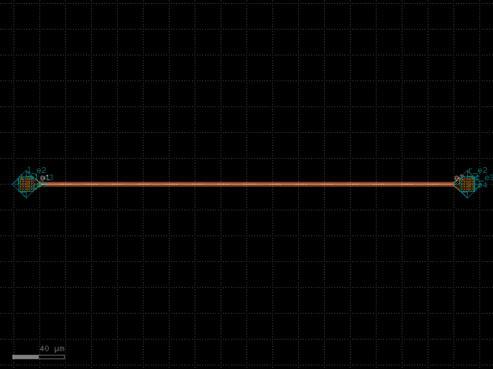
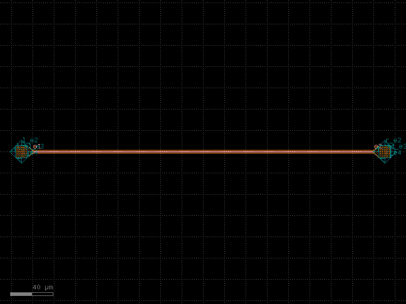
- gdsfactory.components.waveguides.straight_heater_meander_doped(length=300.0, spacing=2.0, cross_section='strip', heater_width=1.5, extension_length=15.0, layers_doping=('P', 'PP', 'PPP'), radius=5.0, via_stack=functools.partial(<function via_stack>, size=(1.5, 1.5), layers=('M1', 'M2'), vias=(functools.partial(<function via>, layer='VIAC', size=(0.1, 0.1), pitch=0.2, enclosure=0.1), functools.partial(<function via>, layer='VIA1', size=(0.1, 0.1), pitch=0.2, enclosure=0.1))), port_orientation1=None, port_orientation2=None, straight_widths=(0.8, 0.9, 0.8), taper_length=10)[source]#
Returns a meander based heater.
based on SungWon Chung, Makoto Nakai, and Hossein Hashemi, Low-power thermo-optic silicon modulator for large-scale photonic integrated systems Opt. Express 27, 13430-13459 (2019) https://www.osapublishing.org/oe/abstract.cfm?URI=oe-27-9-13430
- Parameters:
length (float) – total length of the optical path.
spacing (float) – waveguide spacing (center to center).
cross_section (CrossSectionSpec) – for waveguide.
heater_width (float) – for heater.
extension_length (float) – of input and output optical ports.
layers_doping (LayerSpecs) – doping layers to be used for heater.
radius (float) – for the meander bends.
via_stack (ComponentSpec | None) – for the heater to via_stack metal.
port_orientation1 (float | None) – in degrees. None adds all orientations.
port_orientation2 (float | None) – in degrees. None adds all orientations.
straight_widths (Floats) – width of the straight sections.
taper_length (float) – from the cross_section.
- Return type:
import gdsfactory as gf
gf.gpdk.PDK.activate()
c = gf.components.straight_heater_meander_doped(length=300, spacing=2, cross_section='strip', heater_width=1.5, extension_length=15, layers_doping=('P', 'PP', 'PPP'), radius=5, straight_widths=(0.8, 0.9, 0.8), taper_length=10).copy()
c.draw_ports()
c.plot()
(Source code, png, hires.png, pdf)
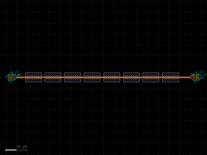
- gdsfactory.components.waveguides.straight_heater_metal(length=320.0, *, length_undercut_spacing=0, length_undercut=5, length_straight=0.1, length_straight_input=0.1, cross_section='strip', cross_section_heater='heater_metal', cross_section_waveguide_heater='strip_heater_metal', cross_section_heater_undercut='strip_heater_metal_undercut', with_undercut=False, via_stack='via_stack_heater_mtop', port_orientation1=None, port_orientation2=None, heater_taper_length=5.0, ohms_per_square=None)#
Returns a thermal phase shifter.
dimensions from https://doi.org/10.1364/OE.27.010456
- Parameters:
length (float) – of the waveguide.
length_undercut_spacing (float) – from undercut regions.
length_undercut (float) – length of each undercut section.
length_straight (float) – length of the straight waveguide.
length_straight_input (float) – from input port to where trenches start.
cross_section (CrossSectionSpec) – for waveguide ports.
cross_section_heater (CrossSectionSpec) – for heated sections. heater metal only.
cross_section_waveguide_heater (CrossSectionSpec) – for heated sections.
cross_section_heater_undercut (CrossSectionSpec) – for heated sections with undercut.
with_undercut (bool) – isolation trenches for higher efficiency.
via_stack (ComponentSpec | None) – via stack.
port_orientation1 (int | None) – left via stack port orientation. None adds all orientations.
port_orientation2 (int | None) – right via stack port orientation. None adds all orientations.
heater_taper_length (float) – minimizes current concentrations from heater to via_stack.
ohms_per_square (float | None) – to calculate resistance.
- Return type:
import gdsfactory as gf
gf.gpdk.PDK.activate()
c = gf.components.straight_heater_metal(length=320, length_undercut_spacing=0, length_undercut=5, length_straight=0.1, length_straight_input=0.1, cross_section='strip', cross_section_heater='heater_metal', cross_section_waveguide_heater='strip_heater_metal', cross_section_heater_undercut='strip_heater_metal_undercut', with_undercut=False, via_stack='via_stack_heater_mtop', heater_taper_length=5).copy()
c.draw_ports()
c.plot()
(Source code, png, hires.png, pdf)
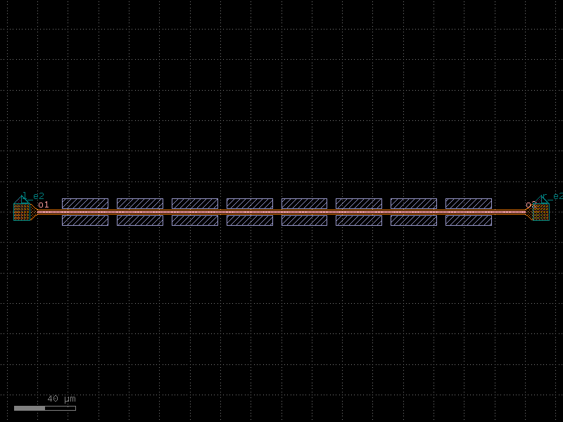
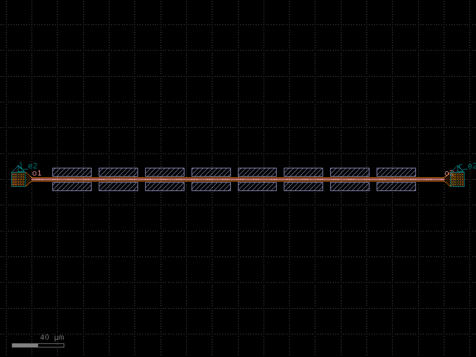

- gdsfactory.components.waveguides.straight_heater_metal_90_90(length=320.0, *, length_undercut_spacing=0, length_undercut=5, length_straight=0.1, length_straight_input=0.1, cross_section='strip', cross_section_heater='heater_metal', cross_section_waveguide_heater='strip_heater_metal', cross_section_heater_undercut='strip_heater_metal_undercut', with_undercut=False, via_stack='via_stack_heater_mtop', port_orientation1=90, port_orientation2=90, heater_taper_length=5.0, ohms_per_square=None)#
Returns a thermal phase shifter.
dimensions from https://doi.org/10.1364/OE.27.010456
- Parameters:
length (float) – of the waveguide.
length_undercut_spacing (float) – from undercut regions.
length_undercut (float) – length of each undercut section.
length_straight (float) – length of the straight waveguide.
length_straight_input (float) – from input port to where trenches start.
cross_section (CrossSectionSpec) – for waveguide ports.
cross_section_heater (CrossSectionSpec) – for heated sections. heater metal only.
cross_section_waveguide_heater (CrossSectionSpec) – for heated sections.
cross_section_heater_undercut (CrossSectionSpec) – for heated sections with undercut.
with_undercut (bool) – isolation trenches for higher efficiency.
via_stack (ComponentSpec | None) – via stack.
port_orientation1 (int | None) – left via stack port orientation. None adds all orientations.
port_orientation2 (int | None) – right via stack port orientation. None adds all orientations.
heater_taper_length (float) – minimizes current concentrations from heater to via_stack.
ohms_per_square (float | None) – to calculate resistance.
- Return type:
import gdsfactory as gf
gf.gpdk.PDK.activate()
c = gf.components.straight_heater_metal_90_90(length=320, length_undercut_spacing=0, length_undercut=5, length_straight=0.1, length_straight_input=0.1, cross_section='strip', cross_section_heater='heater_metal', cross_section_waveguide_heater='strip_heater_metal', cross_section_heater_undercut='strip_heater_metal_undercut', with_undercut=False, via_stack='via_stack_heater_mtop', port_orientation1=90, port_orientation2=90, heater_taper_length=5).copy()
c.draw_ports()
c.plot()
(Source code, png, hires.png, pdf)
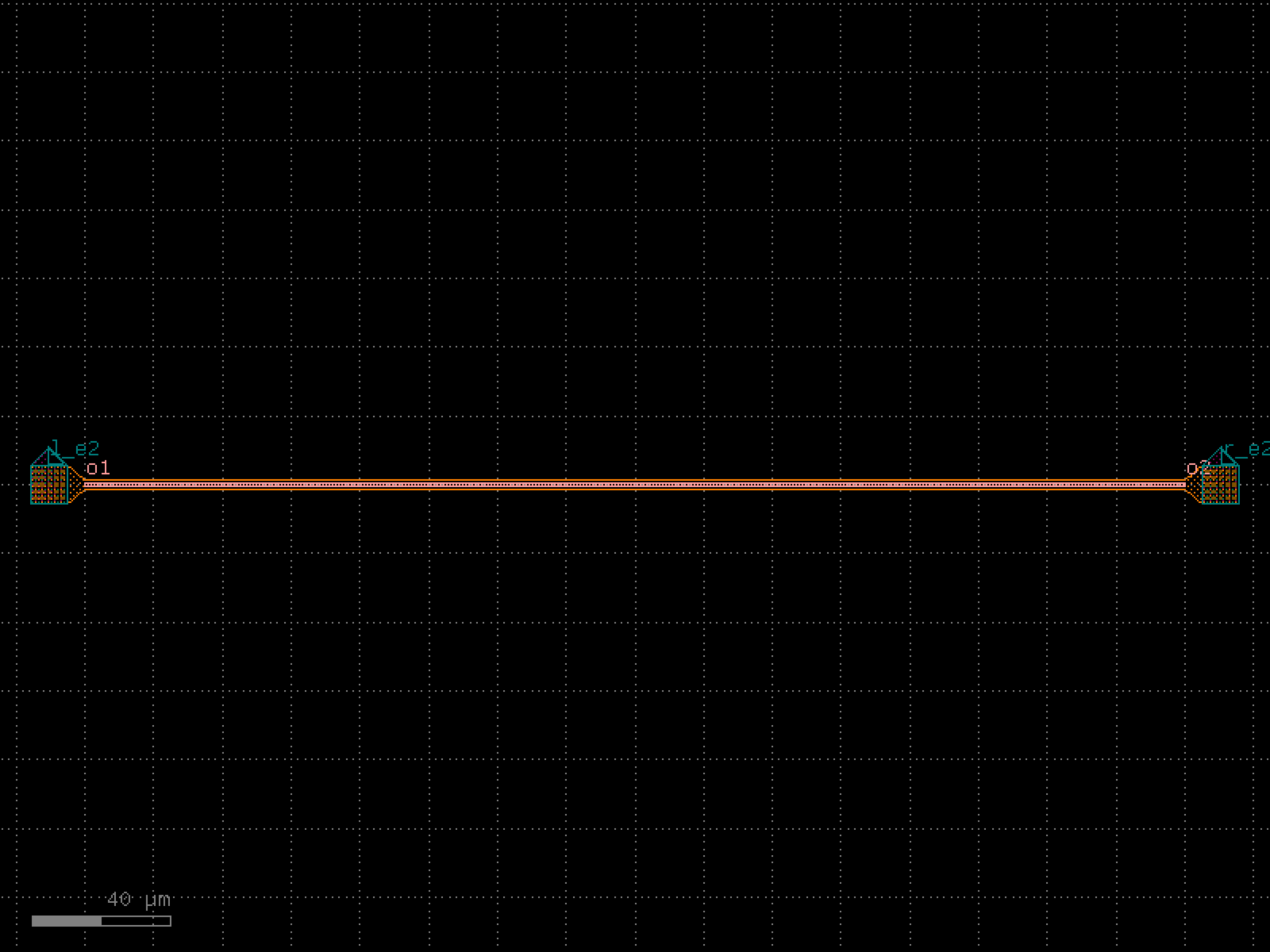
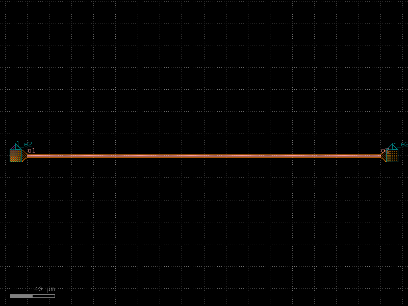
- gdsfactory.components.waveguides.straight_heater_metal_simple(length=320.0, cross_section_heater='heater_metal', cross_section_waveguide_heater='strip_heater_metal', via_stack='via_stack_heater_mtop', port_orientation1=None, port_orientation2=None, heater_taper_length=5.0, ohms_per_square=None)[source]#
Returns a thermal phase shifter that has properly fixed electrical connectivity to extract a suitable electrical netlist and models.
dimensions from https://doi.org/10.1364/OE.27.010456.
- Parameters:
length (float) – of the waveguide.
length_undercut – length of each undercut section.
cross_section_heater (CrossSectionSpec) – for heated sections. heater metal only.
cross_section_waveguide_heater (CrossSectionSpec) – for heated sections.
via_stack (ComponentSpec | None) – via stack.
port_orientation1 (int | None) – left via stack port orientation. None adds all orientations.
port_orientation2 (int | None) – right via stack port orientation. None adds all orientations.
heater_taper_length (float) – minimizes current concentrations from heater to via_stack.
ohms_per_square (float | None) – to calculate resistance.
- Return type:
import gdsfactory as gf
gf.gpdk.PDK.activate()
c = gf.components.straight_heater_metal_simple(length=320, cross_section_heater='heater_metal', cross_section_waveguide_heater='strip_heater_metal', via_stack='via_stack_heater_mtop', heater_taper_length=5).copy()
c.draw_ports()
c.plot()
(Source code, png, hires.png, pdf)
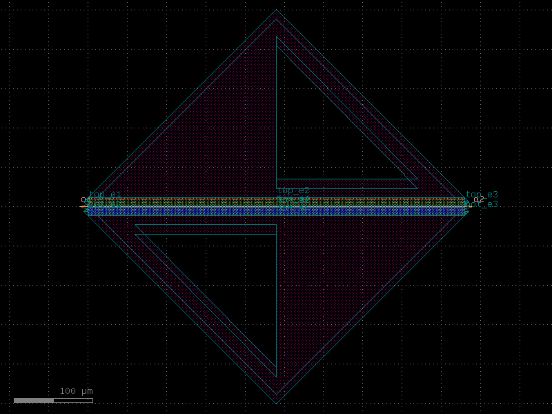
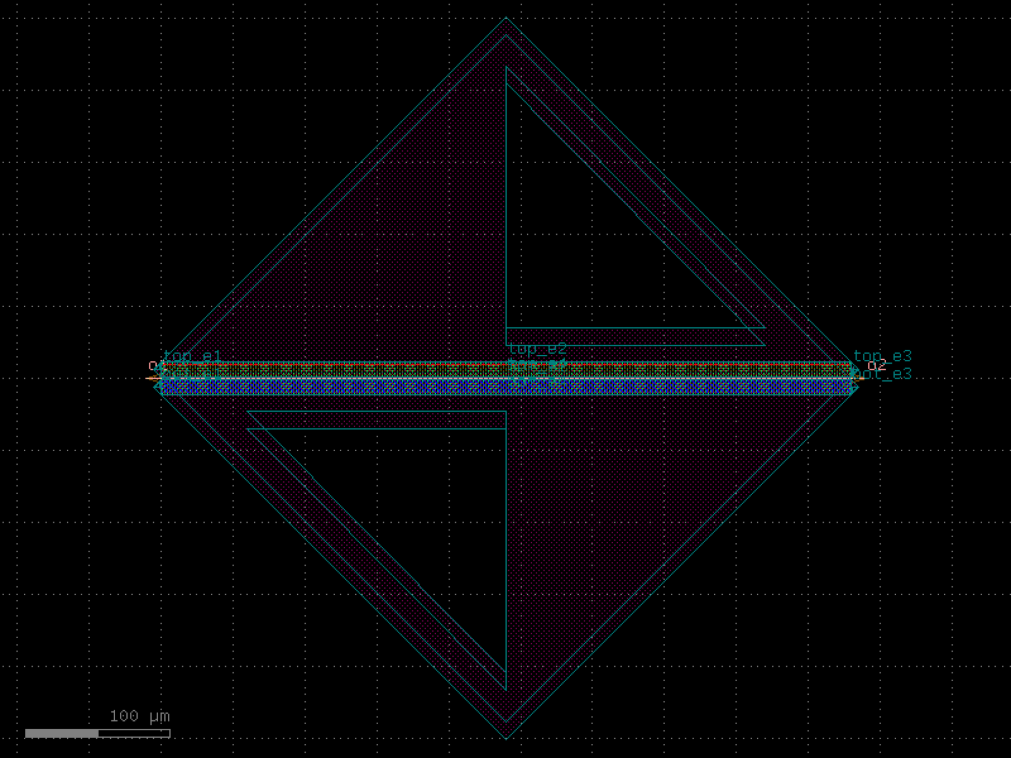

- gdsfactory.components.waveguides.straight_heater_metal_undercut(length=320.0, length_undercut_spacing=6.0, length_undercut=30.0, length_straight=0.1, length_straight_input=15.0, cross_section='strip', cross_section_heater='heater_metal', cross_section_waveguide_heater='strip_heater_metal', cross_section_heater_undercut='strip_heater_metal_undercut', with_undercut=True, via_stack='via_stack_heater_mtop', port_orientation1=None, port_orientation2=None, heater_taper_length=5.0, ohms_per_square=None)[source]#
Returns a thermal phase shifter.
dimensions from https://doi.org/10.1364/OE.27.010456
- Parameters:
length (float) – of the waveguide.
length_undercut_spacing (float) – from undercut regions.
length_undercut (float) – length of each undercut section.
length_straight (float) – length of the straight waveguide.
length_straight_input (float) – from input port to where trenches start.
cross_section (CrossSectionSpec) – for waveguide ports.
cross_section_heater (CrossSectionSpec) – for heated sections. heater metal only.
cross_section_waveguide_heater (CrossSectionSpec) – for heated sections.
cross_section_heater_undercut (CrossSectionSpec) – for heated sections with undercut.
with_undercut (bool) – isolation trenches for higher efficiency.
via_stack (ComponentSpec | None) – via stack.
port_orientation1 (int | None) – left via stack port orientation. None adds all orientations.
port_orientation2 (int | None) – right via stack port orientation. None adds all orientations.
heater_taper_length (float) – minimizes current concentrations from heater to via_stack.
ohms_per_square (float | None) – to calculate resistance.
- Return type:
import gdsfactory as gf
gf.gpdk.PDK.activate()
c = gf.components.straight_heater_metal_undercut(length=320, length_undercut_spacing=6, length_undercut=30, length_straight=0.1, length_straight_input=15, cross_section='strip', cross_section_heater='heater_metal', cross_section_waveguide_heater='strip_heater_metal', cross_section_heater_undercut='strip_heater_metal_undercut', with_undercut=True, via_stack='via_stack_heater_mtop', heater_taper_length=5).copy()
c.draw_ports()
c.plot()
(Source code, png, hires.png, pdf)
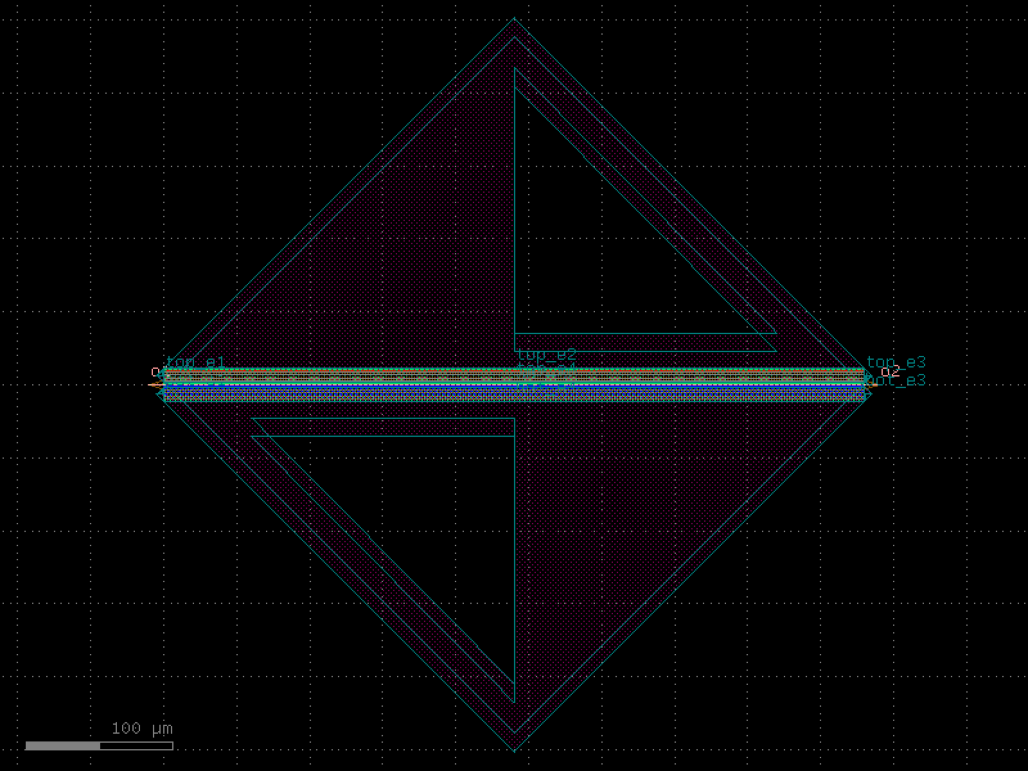

- gdsfactory.components.waveguides.straight_heater_metal_undercut_90_90(length=320.0, length_undercut_spacing=6.0, length_undercut=30.0, length_straight=0.1, length_straight_input=15.0, cross_section='strip', cross_section_heater='heater_metal', cross_section_waveguide_heater='strip_heater_metal', cross_section_heater_undercut='strip_heater_metal_undercut', with_undercut=True, via_stack='via_stack_heater_mtop', *, port_orientation1=90, port_orientation2=90, heater_taper_length=5.0, ohms_per_square=None)#
Returns a thermal phase shifter.
dimensions from https://doi.org/10.1364/OE.27.010456
- Parameters:
length (float) – of the waveguide.
length_undercut_spacing (float) – from undercut regions.
length_undercut (float) – length of each undercut section.
length_straight (float) – length of the straight waveguide.
length_straight_input (float) – from input port to where trenches start.
cross_section (CrossSectionSpec) – for waveguide ports.
cross_section_heater (CrossSectionSpec) – for heated sections. heater metal only.
cross_section_waveguide_heater (CrossSectionSpec) – for heated sections.
cross_section_heater_undercut (CrossSectionSpec) – for heated sections with undercut.
with_undercut (bool) – isolation trenches for higher efficiency.
via_stack (ComponentSpec | None) – via stack.
port_orientation1 (int | None) – left via stack port orientation. None adds all orientations.
port_orientation2 (int | None) – right via stack port orientation. None adds all orientations.
heater_taper_length (float) – minimizes current concentrations from heater to via_stack.
ohms_per_square (float | None) – to calculate resistance.
- Return type:
import gdsfactory as gf
gf.gpdk.PDK.activate()
c = gf.components.straight_heater_metal_undercut_90_90(length=320, length_undercut_spacing=6, length_undercut=30, length_straight=0.1, length_straight_input=15, cross_section='strip', cross_section_heater='heater_metal', cross_section_waveguide_heater='strip_heater_metal', cross_section_heater_undercut='strip_heater_metal_undercut', with_undercut=True, via_stack='via_stack_heater_mtop', port_orientation1=90, port_orientation2=90, heater_taper_length=5).copy()
c.draw_ports()
c.plot()
(Source code, png, hires.png, pdf)
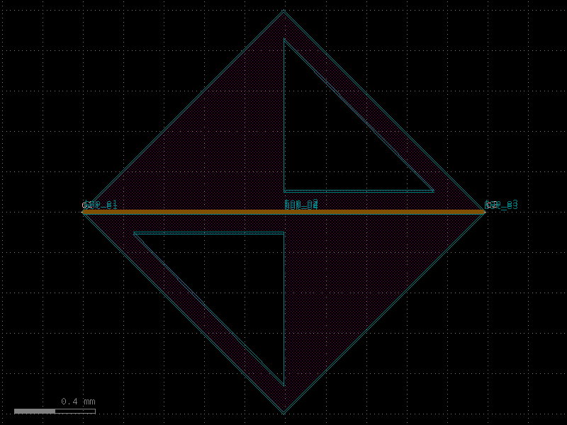

- gdsfactory.components.waveguides.straight_piecewise(x, widths, layer, sections=None, port_names=('o1', 'o2'), name='core', **kwargs)[source]#
Create a component with a piecewise-defined straight waveguide.
- Parameters:
x (Sequence[float] | Path) – X coordinates or a custom Path object.
widths (Sequence[float]) – Waveguide widths at each corresponding x.
layer (tuple[int, int] | str | int | LayerEnum) – Layer to extrude.
sections (Sequence[Section] | None) – Additional cross-section sections to extrude.
port_names (tuple[str | None, str | None]) – Port names for the waveguide.
name (str) – Name for the core (main) Section.
**kwargs (Any) – Additional keyword arguments for the Section.
- Return type:
import gdsfactory as gf
gf.gpdk.PDK.activate()
c = gf.components.straight_piecewise(port_names=('o1', 'o2'), name='core').copy()
c.draw_ports()
c.plot()
- gdsfactory.components.waveguides.straight_pin(length=500.0, cross_section=<function pin>, via_stack='via_stack_slab_m3', via_stack_width=10.0, via_stack_spacing=2, taper='taper_strip_to_ridge')[source]#
Returns rib waveguide with doping and via_stacks used for PN and PIN modulators.
For PIN: https://doi.org/10.1364/OE.26.029983
500um length for PI phase shift https://ieeexplore.ieee.org/document/8268112
to go beyond 2PI, you will need at least 1mm https://ieeexplore.ieee.org/document/8853396/
For PN: Typical lengths in practice are 2-5mm depending on doping,engineering and application: https://opg.optica.org/oe/fulltext.cfm?uri=oe-21-25-30350&id=275107 https://opg.optica.org/oe/fulltext.cfm?uri=oe-20-11-12014&id=233271
- Parameters:
length (float) – of the waveguide.
cross_section (CrossSectionSpec) – for the waveguide.
via_stack (ComponentSpec) – for the via_stacks.
via_stack_width (float) – width of the via_stack.
via_stack_spacing (float) – spacing between via_stacks.
taper (ComponentSpec | None) – optional taper.
- Return type:
import gdsfactory as gf
gf.gpdk.PDK.activate()
c = gf.components.straight_pin(length=500, via_stack='via_stack_slab_m3', via_stack_width=10, via_stack_spacing=2, taper='taper_strip_to_ridge').copy()
c.draw_ports()
c.plot()
(Source code, png, hires.png, pdf)

- gdsfactory.components.waveguides.straight_pin_slot(length=500.0, cross_section='pin', via_stack='via_stack_m1_mtop', via_stack_width=10.0, via_stack_slab='via_stack_slab_m1_horizontal', via_stack_slab_top=None, via_stack_slab_bot=None, via_stack_slab_width=None, via_stack_spacing=3.0, via_stack_slab_spacing=2.0, taper='taper_strip_to_ridge', width=None)[source]#
Returns a PIN straight waveguide with slotted via.
https://doi.org/10.1364/OE.26.029983
500um length for PI phase shift https://ieeexplore.ieee.org/document/8268112
to go beyond 2PI, you will need at least 1mm https://ieeexplore.ieee.org/document/8853396/
- Parameters:
length (float) – of the waveguide.
cross_section (CrossSectionSpec) – for the waveguide.
via_stack (ComponentSpec | None) – for via_stacking the metal.
via_stack_width (float) – in um.
via_stack_slab (ComponentSpec | None) – function for the component via_stacking the slab.
via_stack_slab_top (ComponentSpec | None) – Optional, defaults to via_stack_slab.
via_stack_slab_bot (ComponentSpec | None) – Optional, defaults to via_stack_slab.
via_stack_slab_width (float | None) – defaults to via_stack_width.
via_stack_spacing (float) – spacing between via_stacks.
via_stack_slab_spacing (float) – spacing between via_stacks slabs.
taper (ComponentSpec | None) – optional taper.
width (float | None) – width of the waveguide. If None, it will use the width of the cross_section.
- Return type:
import gdsfactory as gf
gf.gpdk.PDK.activate()
c = gf.components.straight_pin_slot(length=500, cross_section='pin', via_stack='via_stack_m1_mtop', via_stack_width=10, via_stack_slab='via_stack_slab_m1_horizontal', via_stack_spacing=3, via_stack_slab_spacing=2, taper='taper_strip_to_ridge').copy()
c.draw_ports()
c.plot()
(Source code, png, hires.png, pdf)

- gdsfactory.components.waveguides.straight_pn(*, length=2000, cross_section='pn', via_stack='via_stack_slab_m3', via_stack_width=10.0, via_stack_spacing=2, taper='taper_strip_to_ridge')#
Returns rib waveguide with doping and via_stacks used for PN and PIN modulators.
For PIN: https://doi.org/10.1364/OE.26.029983
500um length for PI phase shift https://ieeexplore.ieee.org/document/8268112
to go beyond 2PI, you will need at least 1mm https://ieeexplore.ieee.org/document/8853396/
For PN: Typical lengths in practice are 2-5mm depending on doping,engineering and application: https://opg.optica.org/oe/fulltext.cfm?uri=oe-21-25-30350&id=275107 https://opg.optica.org/oe/fulltext.cfm?uri=oe-20-11-12014&id=233271
- Parameters:
length (float) – of the waveguide.
cross_section (CrossSectionSpec) – for the waveguide.
via_stack (ComponentSpec) – for the via_stacks.
via_stack_width (float) – width of the via_stack.
via_stack_spacing (float) – spacing between via_stacks.
taper (ComponentSpec | None) – optional taper.
- Return type:
import gdsfactory as gf
gf.gpdk.PDK.activate()
c = gf.components.straight_pn(length=2000, cross_section='pn', via_stack='via_stack_slab_m3', via_stack_width=10, via_stack_spacing=2, taper='taper_strip_to_ridge').copy()
c.draw_ports()
c.plot()
(Source code, png, hires.png, pdf)

- gdsfactory.components.waveguides.straight_pn_slot(length=500.0, *, cross_section='pn', via_stack='via_stack_m1_mtop', via_stack_width=10.0, via_stack_slab='via_stack_slab_m1_horizontal', via_stack_slab_top=None, via_stack_slab_bot=None, via_stack_slab_width=None, via_stack_spacing=3.0, via_stack_slab_spacing=2.0, taper='taper_strip_to_ridge', width=None)#
Returns a PIN straight waveguide with slotted via.
https://doi.org/10.1364/OE.26.029983
500um length for PI phase shift https://ieeexplore.ieee.org/document/8268112
to go beyond 2PI, you will need at least 1mm https://ieeexplore.ieee.org/document/8853396/
- Parameters:
length (float) – of the waveguide.
cross_section (CrossSectionSpec) – for the waveguide.
via_stack (ComponentSpec | None) – for via_stacking the metal.
via_stack_width (float) – in um.
via_stack_slab (ComponentSpec | None) – function for the component via_stacking the slab.
via_stack_slab_top (ComponentSpec | None) – Optional, defaults to via_stack_slab.
via_stack_slab_bot (ComponentSpec | None) – Optional, defaults to via_stack_slab.
via_stack_slab_width (float | None) – defaults to via_stack_width.
via_stack_spacing (float) – spacing between via_stacks.
via_stack_slab_spacing (float) – spacing between via_stacks slabs.
taper (ComponentSpec | None) – optional taper.
width (float | None) – width of the waveguide. If None, it will use the width of the cross_section.
- Return type:
import gdsfactory as gf
gf.gpdk.PDK.activate()
c = gf.components.straight_pn_slot(length=500, cross_section='pn', via_stack='via_stack_m1_mtop', via_stack_width=10, via_stack_slab='via_stack_slab_m1_horizontal', via_stack_spacing=3, via_stack_slab_spacing=2, taper='taper_strip_to_ridge').copy()
c.draw_ports()
c.plot()
(Source code, png, hires.png, pdf)
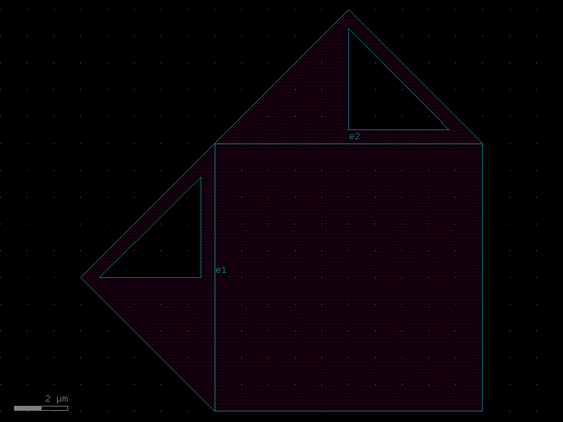
- gdsfactory.components.waveguides.wire_corner(cross_section='metal_routing', port_names=('e1', 'e2'), port_types=('electrical', 'electrical'), width=None, radius=None)[source]#
Returns 45 degrees electrical corner wire.
- Parameters:
cross_section (CrossSectionSpec) – spec.
port_names (Sequence[str]) – port names.
port_types (Sequence[str]) – port types.
width (float | None) – optional width. Defaults to cross_section width.
radius (float | None) – ignored.
- Return type:
import gdsfactory as gf
gf.gpdk.PDK.activate()
c = gf.components.wire_corner(cross_section='metal_routing', port_names=('e1', 'e2'), port_types=('electrical', 'electrical')).copy()
c.draw_ports()
c.plot()
(Source code, png, hires.png, pdf)

- gdsfactory.components.waveguides.wire_corner45(cross_section='metal_routing', radius=10, width=None, layer=None, with_corner90_ports=True)[source]#
Returns 90 degrees electrical corner wire.
- Parameters:
cross_section (CrossSectionSpec) – spec.
radius (float) – in um.
width (float | None) – optional width.
layer (LayerSpec | None) – optional layer.
with_corner90_ports (bool) – if True adds ports at 90 degrees.
- Return type:
import gdsfactory as gf
gf.gpdk.PDK.activate()
c = gf.components.wire_corner45(cross_section='metal_routing', radius=10, with_corner90_ports=True).copy()
c.draw_ports()
c.plot()
(Source code, png, hires.png, pdf)

- gdsfactory.components.waveguides.wire_corner45_straight(width=None, radius=None, cross_section='metal_routing')[source]#
Returns 45 degrees wire straight ends.
- Parameters:
width (float | None) – of the wire.
radius (float | None) – of the corner. Defaults to width.
cross_section (CrossSectionSpec) – metal_routing.
- Return type:
import gdsfactory as gf
gf.gpdk.PDK.activate()
c = gf.components.wire_corner45_straight(cross_section='metal_routing').copy()
c.draw_ports()
c.plot()
(Source code, png, hires.png, pdf)

- gdsfactory.components.waveguides.wire_corner_sections(cross_section='metal_routing', port_type='electrical', **kwargs)[source]#
Returns 90 degrees electrical corner wire, where all cross_section sections properly represented.
Works well with symmetric cross_sections, not quite ready for asymmetric.
- Parameters:
cross_section (CrossSectionSpec) – spec.
port_type (str) – “electrical” or “optical”.
kwargs (Any) – cross_section settings, ignored (such as radius, width, layer).
- Return type:
import gdsfactory as gf
gf.gpdk.PDK.activate()
c = gf.components.wire_corner_sections(cross_section='metal_routing', port_type='electrical').copy()
c.draw_ports()
c.plot()
(Source code, png, hires.png, pdf)

- gdsfactory.components.waveguides.wire_straight(length=10.0, npoints=2, cross_section='metal_routing', width=None)[source]#
Returns a Straight waveguide.
- Parameters:
length (float) – straight length (um).
npoints (int) – number of points.
cross_section (CrossSectionSpec) – specification (CrossSection, string or dict).
width (float | None) – width of the waveguide. If None, it will use the width of the cross_section.
- Return type:
o1 ──────────────── o2 length
import gdsfactory as gf
gf.gpdk.PDK.activate()
c = gf.components.wire_straight(length=10, npoints=2, cross_section='metal_routing').copy()
c.draw_ports()
c.plot()
(Source code, png, hires.png, pdf)
