Cascaded MZI Filter#
This example shows how to assemble components together to form a complex component that can be simulated by integrating gdsfactory, tidy3d, and sax. The design is based on the first stage of the Coarse Wavelength Division Multiplexer presented in S. Dwivedi, P. De Heyn, P. Absil, J. Van Campenhout and W. Bogaerts, “Coarse wavelength division multiplexer on silicon-on-insulator for 100 GbE,” 2015 IEEE 12th International Conference on Group IV Photonics (GFP), Vancouver, BC, Canada, 2015, pp. 9-10, doi: 10.1109/Group4.2015.7305928.
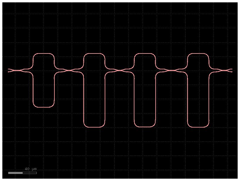
Each filter stage is formed by 4 cascaded Mach-Zenhder Interferometers (MZIs) with predefined delays for the central wavelength. Symmetrical Direction Couplers (DCs) are used to mix the signals at the ends of the MZI arms. In order to facilitate fabrication, all DC gaps are kept equal, so the power transfer ratios are defined by the coupling length of the DCs.
We will design each DC through 3D FDTD simulations to guarantee the desired power ratios, which have been calculated to provide maximally flat response. The S parameters computed through FDTD are latter used in the full circuit simulation along with models for staight and curved waveguide sections, leading to an accurate model that exhibits features similar to those found in experimental data.
from functools import partial

import gdsfactory as gf
import jax
import jax.numpy as jnp
import matplotlib.pyplot as plt
import numpy as np
import sax

import gplugins.tidy3d as gt
from gplugins.common.config import PATH
We start by loading the desired PDK and setting the main geometry and filter parameters, such as DC gap and central wavelength.
fsr = 0.01
gap = 0.15
width = 0.45
wavelengths = np.linspace(1.5, 1.6, 101)
lda_c = wavelengths[wavelengths.size // 2]

pdk = gf.get_active_pdk()


layer_stack = pdk.get_layer_stack()
core = layer_stack.layers["core"]
clad = layer_stack.layers["clad"]
box = layer_stack.layers["box"]

layer_stack.layers.pop("substrate", None)

print(
    f"""Stack:
- {clad.material} clad with {clad.thickness}µm
- {core.material} clad with {core.thickness}µm
- {box.material} clad with {box.thickness}µm"""
)
Stack:
- sio2 clad with 3.0µm
- si clad with 0.22µm
- sio2 clad with 3.0µm
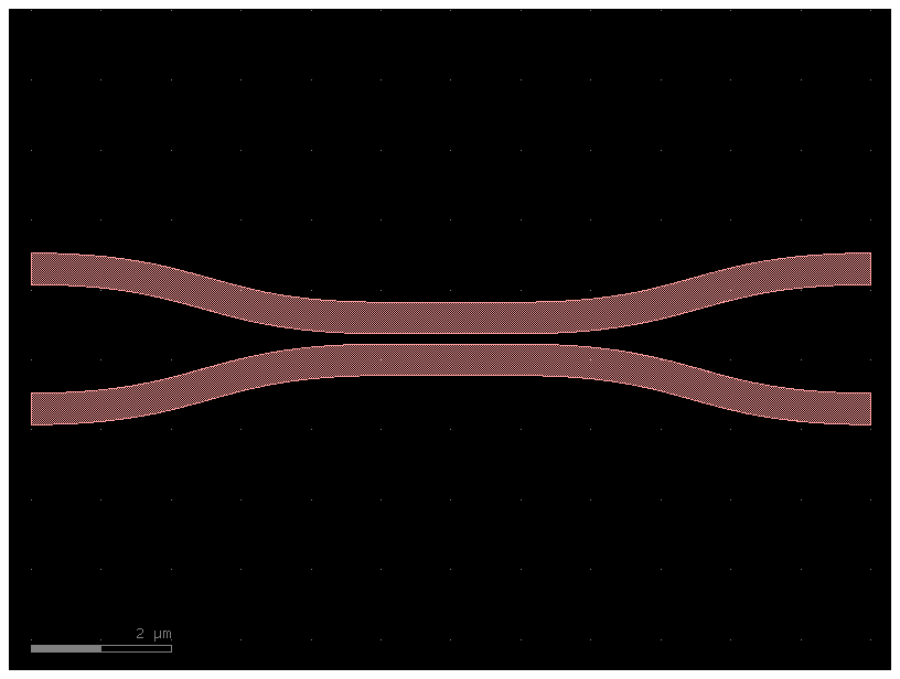
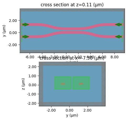
We use the tidy3d plugin to automatically create an FDTD simulation of the complete coupler.
We can inspect the simulation and port modes before running it to make sure our design is correct.
cross_section = pdk.get_cross_section("strip", width=width)

coupler_sc = partial(
    gf.components.coupler,
    gap=gap,
    dx=5,
    dy=2,
    cross_section=cross_section,
)  # Coupler Strip C-Band

coupler = coupler_sc(gap=gap, length=2.0)
coupler.show()  # show it in klayout
coupler.plot()  # plot it
_ = gt.write_sparameters(
    coupler,
    layer_stack=layer_stack,
    plot_simulation_layer_name="core",
)
Because of the smooth S bend regions, the usual analytical models to calculate the power ratio of the DC give only a rough estimate. We sweep a range of DC lengths based on those estimates to find the dimensions required in our design for the given PDK.
sim_lengths = range(20)
jobs = [
    dict(
        component=coupler_sc(gap=gap, length=length, cross_section=cross_section),
        filepath=PATH.sparameters_repo / f"dc_{length}.npz",
        layer_stack=layer_stack,
    )
    for length in sim_lengths
]
sims = gt.write_sparameters_batch(jobs)
s_params_list = [sim.result() for sim in sims]
Simulation loaded from PosixPath('/home/runner/work/gplugins/gplugins/test-data/sp/dc_0.npz')
Simulation loaded from PosixPath('/home/runner/work/gplugins/gplugins/test-data/sp/dc_1.npz')
Simulation loaded from PosixPath('/home/runner/work/gplugins/gplugins/test-data/sp/dc_2.npz')
Simulation loaded from PosixPath('/home/runner/work/gplugins/gplugins/test-data/sp/dc_3.npz')
Simulation loaded from PosixPath('/home/runner/work/gplugins/gplugins/test-data/sp/dc_4.npz')
Simulation loaded from PosixPath('/home/runner/work/gplugins/gplugins/test-data/sp/dc_5.npz')
Simulation loaded from PosixPath('/home/runner/work/gplugins/gplugins/test-data/sp/dc_6.npz')
Simulation loaded from PosixPath('/home/runner/work/gplugins/gplugins/test-data/sp/dc_7.npz')
Simulation loaded from PosixPath('/home/runner/work/gplugins/gplugins/test-data/sp/dc_8.npz')
Simulation loaded from PosixPath('/home/runner/work/gplugins/gplugins/test-data/sp/dc_9.npz')
Simulation loaded from PosixPath('/home/runner/work/gplugins/gplugins/test-data/sp/dc_10.npz')
Simulation loaded from PosixPath('/home/runner/work/gplugins/gplugins/test-data/sp/dc_11.npz')
Simulation loaded from PosixPath('/home/runner/work/gplugins/gplugins/test-data/sp/dc_12.npz')
Simulation loaded from PosixPath('/home/runner/work/gplugins/gplugins/test-data/sp/dc_13.npz')
Simulation loaded from PosixPath('/home/runner/work/gplugins/gplugins/test-data/sp/dc_14.npz')
Simulation loaded from PosixPath('/home/runner/work/gplugins/gplugins/test-data/sp/dc_15.npz')
Simulation loaded from PosixPath('/home/runner/work/gplugins/gplugins/test-data/sp/dc_16.npz')
Simulation loaded from PosixPath('/home/runner/work/gplugins/gplugins/test-data/sp/dc_17.npz')
Simulation loaded from PosixPath('/home/runner/work/gplugins/gplugins/test-data/sp/dc_18.npz')
Simulation loaded from PosixPath('/home/runner/work/gplugins/gplugins/test-data/sp/dc_19.npz')
# s_params_list = [dict(np.load(PATH.sparameters_repo / f"dc_{length}.npz")) for length in sim_lengths]
wavelengths = s_params_list[0]["wavelengths"]
drop = np.array([np.abs(s["o3@0,o1@0"]) ** 2 for s in s_params_list])
thru = np.array([np.abs(s["o4@0,o1@0"]) ** 2 for s in s_params_list])
loss = 1 - (drop + thru)
sim_ratios = drop / (drop + thru)

fig, ax = plt.subplots(2, 2, figsize=(12, 6))

for i in range(0, wavelengths.size, 5):
    ax[0, 0].plot(
        sim_lengths, drop[:, i], label=f"{gf.snap.snap_to_grid(wavelengths[i])}µm"
    )

for i, length in enumerate(sim_lengths):
    ax[0, 1].plot(wavelengths, drop[i, :], label=f"{length}µm")
    ax[1, 0].plot(wavelengths, sim_ratios[i, :], label=f"{length}µm")
    ax[1, 1].plot(wavelengths, loss[i, :], label=f"{length}µm")

ax[0, 0].set_xlabel("Coupler length (µm)")
ax[0, 0].set_ylabel("Drop ratio")
ax[0, 1].set_xlabel("λ (µm)")
ax[0, 1].set_ylabel("Drop ratio")
ax[1, 0].set_xlabel("λ (µm)")
ax[1, 0].set_ylabel("Power ratio")
ax[1, 1].set_xlabel("λ (µm)")
ax[1, 1].set_ylabel("Loss")
ax[0, 0].legend()
fig.tight_layout()
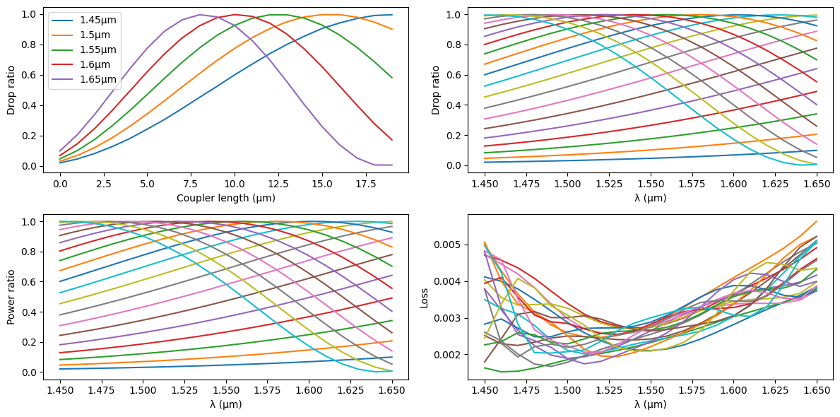
Now we crete a fitting function to calculate the DC length for a given power ratio.
In the filter specification, the desired ratios are 0.5, 0.13, 0.12, 0.5, and 0.25. We calculate the DC lengths accordingly.
def coupler_length(λ: float = 1.55, power_ratio: float = 0.5):
    i0 = np.argmin(np.abs(wavelengths - λ))
    i1 = min(i0 + 1, len(wavelengths) - 1) if λ > wavelengths[i] else max(i0 - 1, 0)
    if i1 != i0:
        pr = (
            sim_ratios[:, i0] * (wavelengths[i1] - λ)
            + sim_ratios[:, i1] * (λ - wavelengths[i0])
        ) / (wavelengths[i1] - wavelengths[i0])
    else:
        pr = sim_ratios[:, i0]
    y = pr - power_ratio
    root_indices = np.flatnonzero(y[1:] * y[:-1] <= 0)
    if len(root_indices) == 0:
        return sim_lengths[np.argmin(np.abs(y))]
    j = root_indices[0]
    return (
        sim_lengths[j] * (pr[j + 1] - power_ratio)
        + sim_lengths[j + 1] * (power_ratio - pr[j])
    ) / (pr[j + 1] - pr[j])


power_ratios = [0.50, 0.13, 0.12, 0.50, 0.25]
lengths = [gf.snap.snap_to_grid(coupler_length(lda_c, pr)) for pr in power_ratios]
print("Power ratios:", power_ratios)
print("Lengths:", lengths)
Power ratios: [0.5, 0.13, 0.12, 0.5, 0.25]
Lengths: [5.26, 1.386, 1.251, 5.26, 2.831]
Finally, we simulate the couplers with the calculated lengths to guarantee the fitting error is within tolerance. As expected, all couplers have the correct power ratios at the central wavelength.
sims = gt.write_sparameters_batch(
    [
        {
            "component": coupler_sc(gap=gap, length=length),
            "filepath": PATH.sparameters_repo / f"dc_{length}.npz",
        }
        for length in lengths
    ],
    layer_stack=layer_stack,
    # overwrite=True,
)
s_params_list = [sim.result() for sim in sims]
fig, ax = plt.subplots(1, 3, figsize=(12, 3))
errors = []
i = wavelengths.size // 2

for pr, sp in zip(power_ratios, s_params_list):
    drop = np.abs(sp["o3@0,o1@0"]) ** 2
    thru = np.abs(sp["o4@0,o1@0"]) ** 2

    assert lda_c == wavelengths[i]
    errors.append(drop[i] / (thru[i] + drop[i]) - pr)

    ax[0].plot(wavelengths, thru, label=f"{1 - pr}")
    ax[1].plot(wavelengths, drop, label=f"{pr}")
    ax[2].plot(wavelengths, 1 - thru - drop)

ax[0].set_ylabel("Thru ratio")
ax[1].set_ylabel("Drop ratio")
ax[2].set_ylabel("Loss")
ax[0].set_ylim(0, 1)
ax[1].set_ylim(0, 1)
ax[0].legend()
ax[1].legend()
fig.tight_layout()
print(errors)
[np.float64(6.434420104062255e-06), np.float64(-0.002109990202947526), np.float64(-0.0014052341754183795), np.float64(6.434420104062255e-06), np.float64(-0.0009526701131395698)]

Now we have to design the arms of each MZI. The most important parameter here is their free spectral range (FSR), which comes from the path length difference and the group index of the waveguide at the central wavelength:
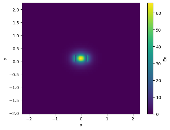
We calculate the group index for our waveguides through tidy3d’s local mode solver. Because we’re interested in precise dispersion, we use a dense mesh and high precision in these calculations.
The path length differences for the MZIs are \(\Delta L\), \(2\Delta L\), \(L_\pi - 2\Delta L\), and \(-2\Delta L\), with \(L_\pi\) the length required for \(\pi\) phase shift (negative values indicate a delay in the opposite arm to positive values).
def mzi_path_difference(waveguide: gt.modes.Waveguide, group_index: float, fsr: float):
    return waveguide.wavelength**2 / (fsr * group_index)


nm = 1e-3

mode_solver_specs = dict(
    core_material=core.material,
    clad_material=clad.material,
    core_width=width,
    core_thickness=core.thickness,
    box_thickness=min(2.0, box.thickness),
    clad_thickness=min(2.0, clad.thickness),
    side_margin=2.0,
    num_modes=2,
    grid_resolution=20,
    precision="double",
)

waveguide_solver = gt.modes.Waveguide(
    wavelength=lda_c, **mode_solver_specs, group_index_step=True
)

waveguide_solver.plot_field(field_name="Ex", mode_index=0)
ng = waveguide_solver.n_group[0]
ne = waveguide_solver.n_eff[0].real
print(f"ne = {ne}, ng = {ng}")

length_delta = mzi_path_difference(waveguide_solver, ng, fsr)
length_pi = lda_c / (2 * ne)
mzi_deltas = (
    length_delta,
    2 * length_delta,
    length_pi - 2 * length_delta,
    -2 * length_delta,
)
print(f"Path difference (ΔL = {length_delta}, Lπ = {length_pi}):", mzi_deltas)
ne = 2.4053688822144013, ng = 4.287761306050167
Path difference (ΔL = 56.03157052166119, Lπ = 0.3221959033936321): (np.float64(56.03157052166119), np.float64(112.06314104332237), np.float64(-111.74094513992874), np.float64(-112.06314104332237))
Next we create a helper function that returns the MZI arms for a given length difference, respecting the bend radius defined in our PDK.
layout = gf.c.mzi_lattice(
    coupler_gaps=(gap,) * len(lengths),
    coupler_lengths=tuple(lengths),
    delta_lengths=tuple([abs(x) for x in mzi_deltas]),
    cross_section="strip",
)
layout.plot()
Finally, we want to build a complete simulation of the filter based on individual models for its components.
We extract the filter netlist and verify we’ll need models for the straight and bend sections, as well as for the DCs.
netlist = layout.get_netlist()
{v["component"] for v in netlist["instances"].values()}
{'mzi'}
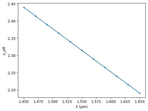
The model for the straight sections is based directly on the waveguide mode, including dispersion effects.
straight_wavelengths = jnp.linspace(wavelengths[0], wavelengths[-1], 11)
straight_neffs = np.empty(straight_wavelengths.size, dtype=complex)

waveguide_solver = gt.modes.Waveguide(
    wavelength=list(straight_wavelengths), **mode_solver_specs
)
straight_neffs = waveguide_solver.n_eff[:, 0]

plt.plot(straight_wavelengths, straight_neffs.real, ".-")
plt.xlabel("λ (µm)")
plt.ylabel("n_eff")
20:05:01 UTC WARNING: The group index was not computed. To calculate group
             index, pass 'group_index_step = True' in the 'ModeSpec'.
Text(0, 0.5, 'n_eff')
@jax.jit
def complex_interp(xs, x, y):
    ys_mag = jnp.interp(xs, x, jnp.abs(y))
    ys_phase = jnp.interp(xs, x, jnp.unwrap(jnp.angle(y)))
    return ys_mag * jnp.exp(1j * ys_phase)


@jax.jit
def straight_model(wl=1.55, length: float = 1.0):
    n_eff = complex_interp(wl, straight_wavelengths, straight_neffs.real)
    s21 = jnp.exp(2j * jnp.pi * n_eff * length / wl)
    zero = jnp.zeros_like(wl)
    return {
        ("o1", "o1"): zero,
        ("o1", "o2"): s21,
        ("o2", "o1"): s21,
        ("o2", "o2"): zero,
    }


straight_model()
{('o1', 'o1'): Array(0., dtype=float64, weak_type=True),
 ('o1', 'o2'): Array(-0.99911567+0.04204618j, dtype=complex128),
 ('o2', 'o1'): Array(-0.99911567+0.04204618j, dtype=complex128),
 ('o2', 'o2'): Array(0., dtype=float64, weak_type=True)}
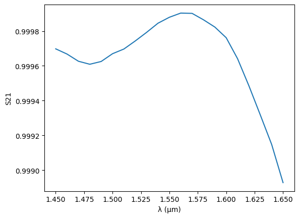
For the bends, we want to include the full S matrix, because we are not using a circular shape, so simple modal decomposition becomes less accurate. Similarly, we want to use the full simulated S matrix from the DCs in our model, instead of analytical approximations.
We encapsulate the S parameter calculation in a helper function that generates the jax model for each component.
def bend_model(cross_section: gf.typings.CrossSectionSpec = "strip"):
    component = gf.components.bend_euler(cross_section=cross_section)
    s = gt.write_sparameters(
        component=component,
        filepath=PATH.sparameters_repo / "bend_filter.npz",
        layer_stack=layer_stack,
    )
    wavelengths = s.pop("wavelengths")

    @jax.jit
    def _model(wl=1.55):
        s11 = complex_interp(wl, wavelengths, s["o1@0,o1@0"])
        s21 = complex_interp(wl, wavelengths, s["o2@0,o1@0"])
        return {
            ("o1", "o1"): s11,
            ("o1", "o2"): s21,
            ("o2", "o1"): s21,
            ("o2", "o2"): s11,
        }

    return _model


bend_model(cross_section=cross_section)()
Simulation loaded from PosixPath('/home/runner/work/gplugins/gplugins/test-data/sp/bend_filter.npz')
{('o1', 'o1'): Array(0.00117895+0.00035561j, dtype=complex128),
 ('o1', 'o2'): Array(0.34397268-0.93891534j, dtype=complex128),
 ('o2', 'o1'): Array(0.34397268-0.93891534j, dtype=complex128),
 ('o2', 'o2'): Array(0.00117895+0.00035561j, dtype=complex128)}
c = gf.Component(name="bend")
ref = c.add_ref(gf.components.bend_euler(cross_section=cross_section))
c.add_ports(ref.ports)
x, _ = sax.circuit(
    c.get_netlist(), {"bend_euler": bend_model(cross_section=cross_section)}
)

s = x(wl=wavelengths)
plt.plot(wavelengths, jnp.abs(s[("o1", "o2")]) ** 2)
plt.ylabel("S21")
plt.xlabel("λ (µm)")
Simulation loaded from PosixPath('/home/runner/work/gplugins/gplugins/test-data/sp/bend_filter.npz')
Text(0.5, 0, 'λ (µm)')
def coupler_model(
    gap: float = 0.1,
    length: float = 1.0,
    dx: float = 5.0,
    dy: float = 2.0,
    cross_section: gf.typings.CrossSectionSpec = "strip",
):
    component = coupler_sc(
        gap=gap,
        length=length,
        dx=dx,
        dy=dy,
    )
    separation = 2.0
    bend_factor = 4.0
    s = gt.write_sparameters(
        component=component,
        filepath=PATH.sparameters_repo
        / f"coupler_filter_gap={gap}_length={length}_s={separation}_bf={bend_factor}.npz",
    )
    wavelengths = s.pop("wavelengths")

    @jax.jit
    def _model(wl=1.55):
        s11 = complex_interp(wl, wavelengths, s["o1@0,o1@0"])
        s21 = complex_interp(wl, wavelengths, s["o2@0,o1@0"])
        s31 = complex_interp(wl, wavelengths, s["o3@0,o1@0"])
        s41 = complex_interp(wl, wavelengths, s["o4@0,o1@0"])
        return {
            ("o1", "o1"): s11,
            ("o1", "o2"): s21,
            ("o1", "o3"): s31,
            ("o1", "o4"): s41,
            ("o2", "o1"): s21,
            ("o2", "o2"): s11,
            ("o2", "o3"): s41,
            ("o2", "o4"): s31,
            ("o3", "o1"): s31,
            ("o3", "o2"): s41,
            ("o3", "o3"): s11,
            ("o3", "o4"): s21,
            ("o4", "o1"): s41,
            ("o4", "o2"): s31,
            ("o4", "o3"): s21,
            ("o4", "o4"): s11,
        }

    return _model


coupler_model(
    gap=gap,
    length=lengths[0],
    cross_section=cross_section,
)()
Simulation loaded from PosixPath('/home/runner/work/gplugins/gplugins/test-data/sp/coupler_filter_gap=0.15_length=5.26_s=2.0_bf=4.0.npz')
{('o1', 'o1'): Array(-0.0005026-6.19216204e-05j, dtype=complex128),
 ('o1', 'o2'): Array(9.31204395e-06-0.00016022j, dtype=complex128),
 ('o1', 'o3'): Array(-0.17722186-0.68368743j, dtype=complex128),
 ('o1', 'o4'): Array(-0.6833592+0.17844739j, dtype=complex128),
 ('o2', 'o1'): Array(9.31204395e-06-0.00016022j, dtype=complex128),
 ('o2', 'o2'): Array(-0.0005026-6.19216204e-05j, dtype=complex128),
 ('o2', 'o3'): Array(-0.6833592+0.17844739j, dtype=complex128),
 ('o2', 'o4'): Array(-0.17722186-0.68368743j, dtype=complex128),
 ('o3', 'o1'): Array(-0.17722186-0.68368743j, dtype=complex128),
 ('o3', 'o2'): Array(-0.6833592+0.17844739j, dtype=complex128),
 ('o3', 'o3'): Array(-0.0005026-6.19216204e-05j, dtype=complex128),
 ('o3', 'o4'): Array(9.31204395e-06-0.00016022j, dtype=complex128),
 ('o4', 'o1'): Array(-0.6833592+0.17844739j, dtype=complex128),
 ('o4', 'o2'): Array(-0.17722186-0.68368743j, dtype=complex128),
 ('o4', 'o3'): Array(9.31204395e-06-0.00016022j, dtype=complex128),
 ('o4', 'o4'): Array(-0.0005026-6.19216204e-05j, dtype=complex128)}
We must take care of using one model for each DC based on its length, so we use another helper function that iterates over the netlist instances and generates the appropriate model for each one:
import inspect


def patch_netlist(netlist, models, models_to_patch):
    instances = netlist["instances"]
    for name in instances:
        model = instances[name]
        if model["component"] in models_to_patch:
            component = model["component"]
            i = 0
            new_component = f"{component}_v{i}"
            while new_component in models:
                i += 1
                new_component = f"{component}_v{i}"
            settings = model["settings"]
            settings_fitered = {
                k: v
                for k, v in settings.items()
                if k in inspect.signature(models_to_patch[component]).parameters
            }
            models[new_component] = models_to_patch[model["component"]](
                **settings_fitered
            )
            del model["settings"]
            model["component"] = new_component
    return netlist, models


pl_set = sorted(set(zip(power_ratios, lengths)))
fig, ax = plt.subplots(len(pl_set), 1, figsize=(4, 3 * len(pl_set)))

for i, (pr, length) in enumerate(pl_set):
    c = gf.Component()
    ref = c.add_ref(
        coupler_sc(
            gap,
            length,
        )
    )
    c.add_ports(ref.ports)
    netlist, models = patch_netlist(c.get_netlist(), {}, {"coupler": coupler_model})
    x, _ = sax.circuit(netlist, models)
    s = x(wl=wavelengths)
    ax[i].plot(wavelengths, jnp.abs(s[("o1", "o3")]) ** 2, label="Cross")
    ax[i].plot(wavelengths, jnp.abs(s[("o1", "o4")]) ** 2, label="Through")
    ax[i].axvline(lda_c, c="tab:gray", ls=":", lw=1)
    ax[i].set_ylim(0, 1)
    ax[i].set_xlabel("λ (µm)")
    ax[i].set_title(f"l = {length:.2f} µm ({pr})")

ax[0].legend()
fig.tight_layout()
Simulation loaded from PosixPath('/home/runner/work/gplugins/gplugins/test-data/sp/coupler_filter_gap=0.15_length=1.251_s=2.0_bf=4.0.npz')
Simulation loaded from PosixPath('/home/runner/work/gplugins/gplugins/test-data/sp/coupler_filter_gap=0.15_length=1.386_s=2.0_bf=4.0.npz')
Simulation loaded from PosixPath('/home/runner/work/gplugins/gplugins/test-data/sp/coupler_filter_gap=0.15_length=2.831_s=2.0_bf=4.0.npz')
Simulation loaded from PosixPath('/home/runner/work/gplugins/gplugins/test-data/sp/coupler_filter_gap=0.15_length=5.26_s=2.0_bf=4.0.npz')

netlist.keys()
dict_keys(['nets', 'instances', 'placements', 'ports', 'name'])
netlist["instances"].keys()
dict_keys(['coupler_gdsfactorypcomponentspcouplerspcoupler_G0p15_L5_a0feaadb_0_0'])
instance_name = list(netlist["instances"].keys())[0]
netlist["instances"][instance_name]
{'component': 'coupler_v0',
 'info': {'path_length': 15.398, 'min_bend_radius': 6.797}}
Finally, we can simulate the complete filter response around the central wavelength and get the desired FSR and box-like shape.
# fig, ax = plt.subplots(1, 1, figsize=(12, 4))
# netlist, models = patch_netlist(
#    netlist=layout.get_netlist(recursive=True),
#    models={"straight": straight_model, "bend_euler": bend_model(cross_section=cross_section)},
#   models_to_patch={"coupler": coupler_model},
# )
# circuit, _ = sax.circuit(netlist, models)
# lda = np.linspace(1.5, 1.6, 1001)
# s = circuit(wl=lda)
# ax.plot(lda, 20 * jnp.log10(jnp.abs(s[("o1", "o3")])), label="Cross")
# ax.plot(lda, 20 * jnp.log10(jnp.abs(s[("o1", "o4")])), label="Thru")
# ax.set_ylim(-30, 0)
# ax.set_xlabel("λ (µm)")
# ax.legend()
