Grid snapping#
GDS represents points as integers where each point corresponds to a database unit (DBU). Typically, in most foundries, the default DBU is set to 1 nanometer (1nm).
GDSFactory snaps ports to the grid by default to avoid grid snapping errors which are common in layout designs.
If you want to connect components off-grid you need to create a virtual cell, which operates in floats instead of DBUs.
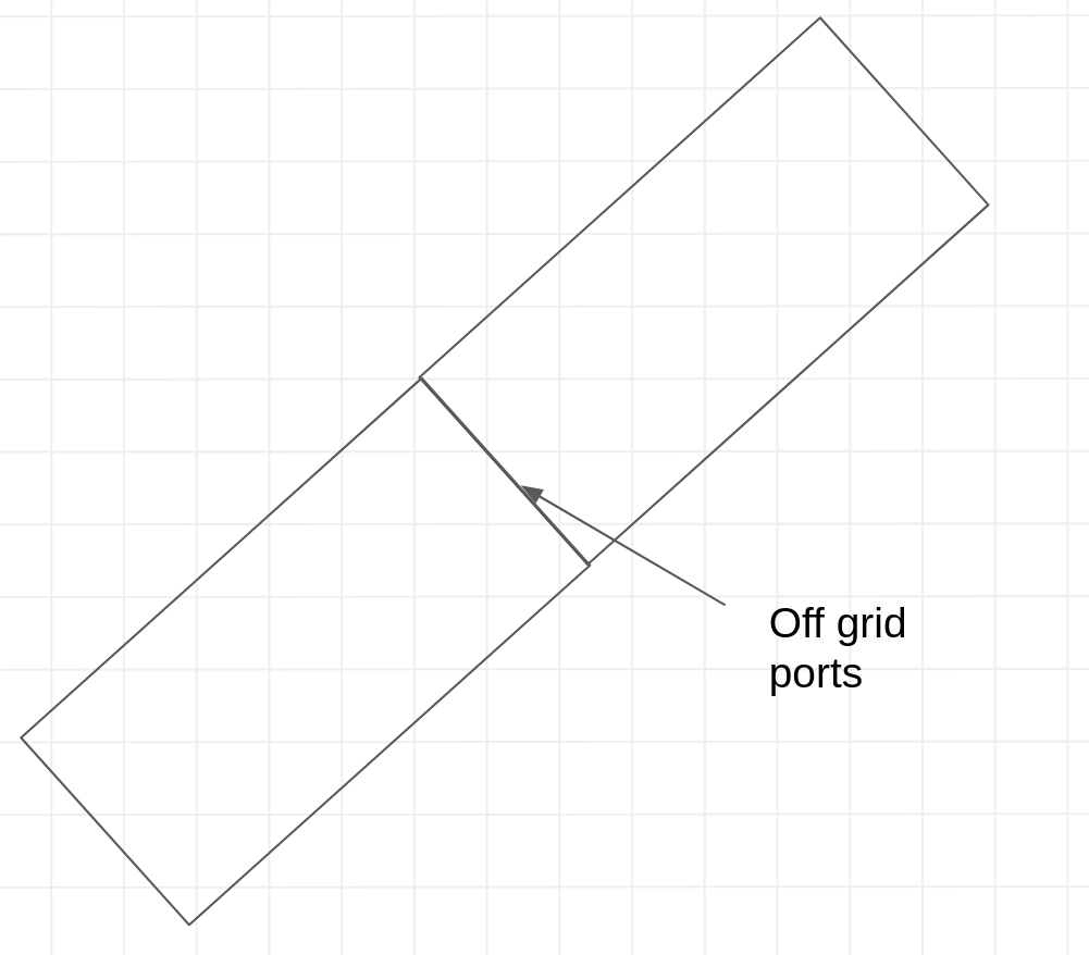
Example of grid snapping errors.
import gdsfactory as gf

gf.gpdk.PDK.activate()
nm = 1e-3
wg1 = gf.Component()
wg1.add_polygon(
    [(0, 0), (1.4 * nm, 0), (1.4 * nm, 1 * nm), (0, 1 * nm)], layer=(1, 0)
)  # rounds to 1 nm

wg1.add_polygon(
    [(0, 3 * nm), (1.6 * nm, 3 * nm), (1.6 * nm, 4 * nm), (0, 4 * nm)], layer=(1, 0)
)  # rounds to 2 nm

wg1.plot()

Changing DBU#
The default DBU (database unit) is set to 1 nm, but you can customize it to other values, such as 5 nm, depending on your design requirements.
gf.kcl.dbu = 5e-3 # set 1 DataBase Unit to 5 nm
This script highlights the effect of rounding when the dbu is set to 5 nm. The discrepancies occur because the coordinate values are snapped to the nearest grid point, which is a multiple of 5 nm in this case.
This can lead to visual or functional differences when designing components with precise tolerances.
wg1 = gf.Component()
DBU = 5e-3
LAYER = (1, 0)

# Add polygons with intentional coordinates to show rounding errors.
# Coordinate values that do not align perfectly with 5 nm dbu.
polygon1_coords = [
    (0, 0),
    (1.7 * DBU, 0),  # 1.7 * 5 nm = 8.5 nm, which will round to 10 nm.
    (1.7 * DBU, 1.3 * DBU),  # 1.3 * 5 nm = 6.5 nm, which will round to 5 nm.
    (0, 1.3 * DBU)
]
wg1.add_polygon(polygon1_coords, layer=LAYER)

polygon2_coords = [
    (0, 2.1 * DBU),  # 2.1 * 5 nm = 10.5 nm, which will round to 10 nm.
    (2.4 * DBU, 2.1 * DBU),  # 2.4 * 5 nm = 12 nm (aligned, no rounding).
    (2.4 * DBU, 3.9 * DBU),  # 3.9 * 5 nm = 19.5 nm, which will round to 20 nm.
    (0, 3.9 * DBU)
]
wg1.add_polygon(polygon2_coords, layer=LAYER)
wg1

gf.kcl.dbu = 1e-3 # Change back 1 DataBase Unit to 1 nm.
⚠️ Warning: Manhattan Orientations#
It’s crucial to always maintain ports with Manhattan orientations (0, 90, 180, 270 degrees). Non-Manhattan ports can lead to ports snapping off the grid, resulting in 1nm gaps in your layouts, which can be detrimental to the design’s integrity.
Although gdsfactory provides functions to connect and route component ports that are off-grid or have non-Manhattan orientations.
Note: If you intend to create off-grid ports and non-Manhattan connections, you must enable this feature manually. This should be done with caution and a thorough understanding of the potential implications on your design.
c = gf.Component()
w1 = c << gf.c.straight(length=4 * nm, width=4 * nm)
w1.rotate(45)

w2 = c << gf.c.straight(length=4 * nm, width=4 * nm)
w2.connect("o1", w1["o2"])
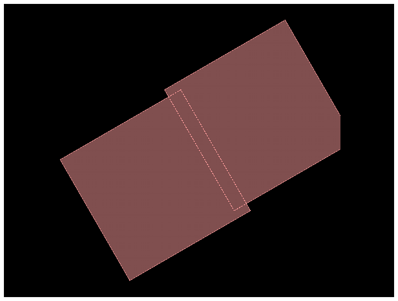
c  # In this case ports overlap by an extra nm because of the rotation, instead of connecting them with no overlap.
c = gf.Component()
w1 = c << gf.components.straight(length=4 * nm, width=4 * nm)
w1.rotate(30)

w2 = c << gf.components.straight(length=4 * nm, width=4 * nm)
w2.connect("o1", w1["o2"])
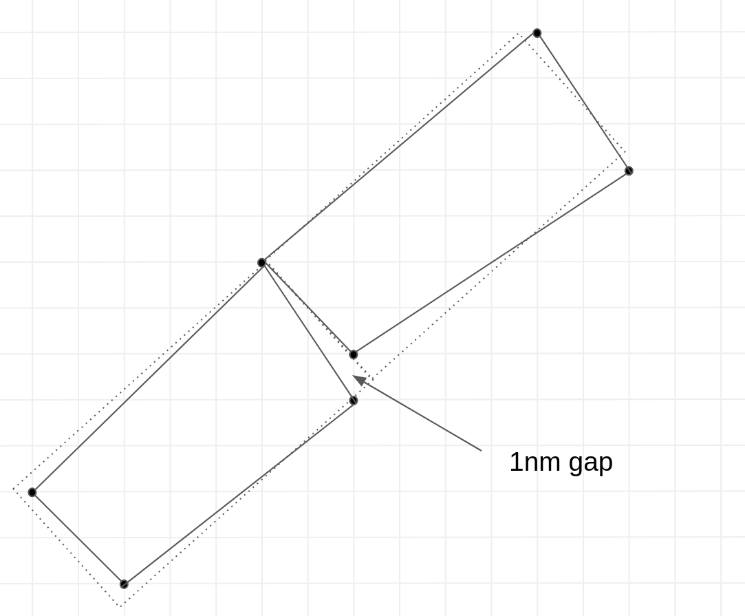
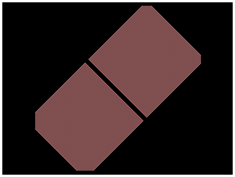
c  # In this case ports have a 1nm gap error because of the rotation.
Fix Non manhattan connections#
The GDS format often has issues with non-manhattan shapes, due to the rounding of vertices to a unit grid and to downstream tools (i.e. DRC) which often tend to assume cell references only have rotations at 90 degree intervals.
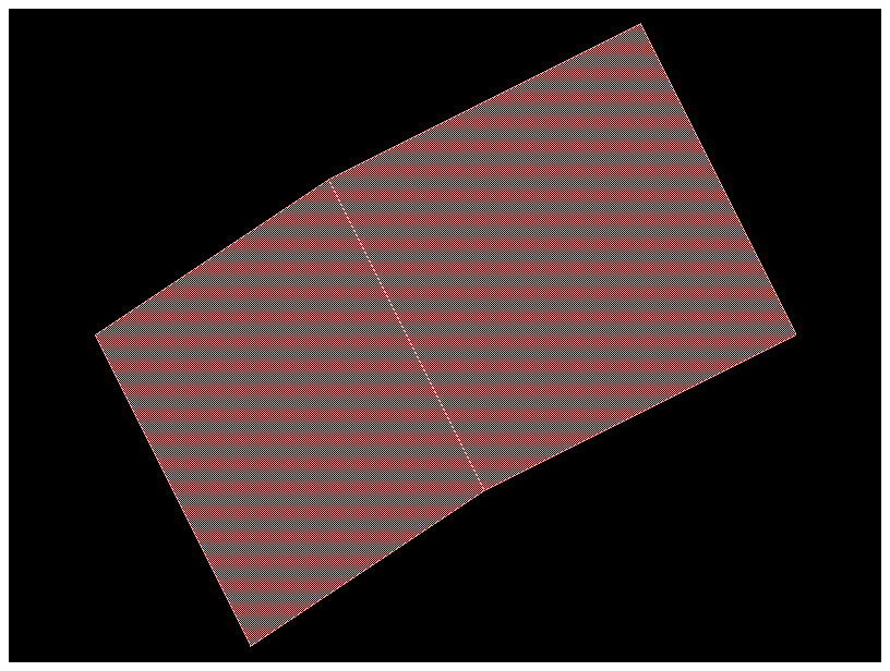
To fix it, you can insert them as virtual instances.
For example:
import gdsfactory as gf

nm = 1e-3
c = gf.Component()
w = gf.components.straight(length=4 * nm, width=4 * nm)

# An instance of component w1 is added to the main component c and then rotated by 30 degrees.
w1 = c.add_ref_off_grid(w)
w1.rotate(30)

# A second instance of w is added.
# The connect function then automatically moves and rotates this second instance (w2),
# so that its input port (o1) is perfectly aligned with the output port (o2) of the first, rotated instance (w1).
w2 = c.add_ref_off_grid(w)
w2.connect("o1", w1["o2"])
c
import gdsfactory as gf


def demo_non_manhattan():
    c = gf.Component()
    b = c << gf.components.bend_circular(angle=30)
    s = c << gf.components.straight(length=5)
    s.connect("o1", b.ports["o2"])
    return c


c1 = demo_non_manhattan()
c1
/home/runner/work/gdsfactory/gdsfactory/.venv/lib/python3.11/site-packages/cachetools/_cached.py:185: UserWarning: bend_euler angle should be 90 or 180. Got 30. Use bend_euler_all_angle instead.
  v = func(*args, **kwargs)
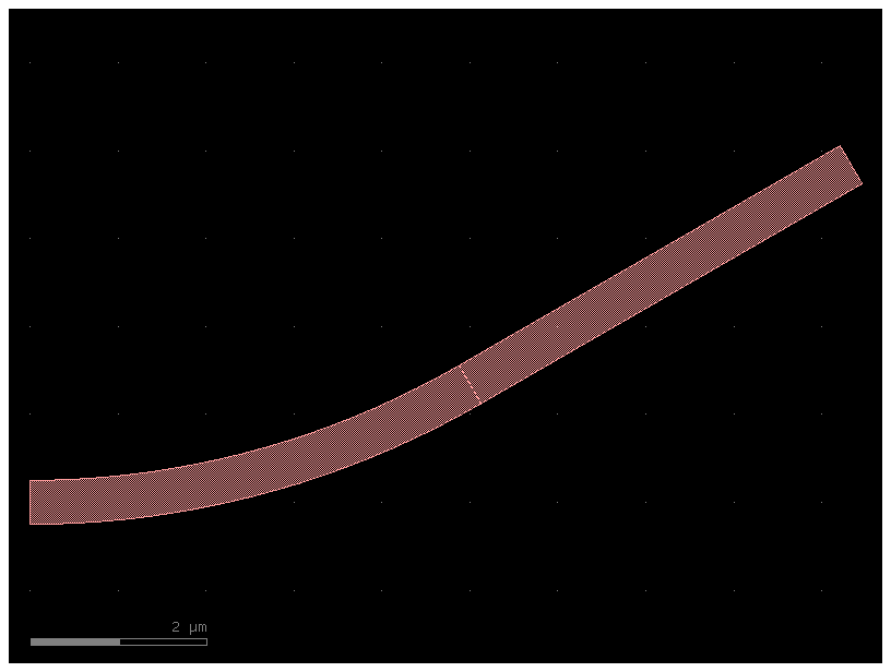
if you zoom in between the bends you will see a notch between waveguides due to non-manhattan connection between the bends.

Solution#
import gdsfactory as gf


@gf.vcell
def snap_bends() -> gf.ComponentAllAngle:

    # Instead of a standard gf.Component, a ComponentAllAngle is created.
    # This special container is necessary for managing shapes that are not restricted to 90-degree angles.
    c = gf.ComponentAllAngle()

    # A 37-degree Euler bend, designed for low-loss arbitrary angle turns, is created.
    # Two instances are placed in the component, and the second (b2) is connected to the end of the first (b1) to create a continuous, smooth curve.
    b = gf.c.bend_euler_all_angle(angle=37)
    b1 = c << b
    b2 = c << b
    b2.connect("o1", b1.ports["o2"])
    c.add_port("o1", port=b1.ports["o1"])
    c.add_port("o2", port=b2.ports["o2"])
    return c

# The final component c consists of the two 37-degree bends connected end-to-end, forming a single waveguide path that turns by a total of 74 degrees.
c = snap_bends()
c.show()
c
2026-02-13 15:25:32.109 | WARNING | kfactory.kcell:show:3968 - Could not connect to klive server
2026-02-13 15:25:32.123 | ERROR    | kfactory.kcell:name:688 - Name conflict in kfactory.kcell::name at line 688
Renaming Unnamed_14 (cell_index=14) to snap_bends would cause it to be named the same as:
 - snap_bends (cell_index=11), function_name=None, basename=None
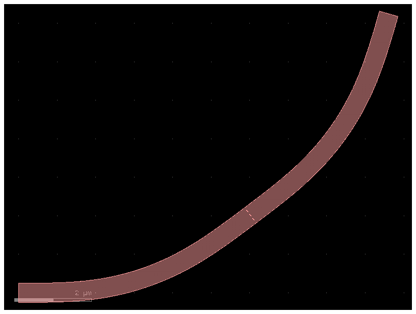
If you zoom into the connection you will now see a perfect connection:
